Week 4- Rolling operation
AIM:For this challenge, we will have to simulate the rolling operation on a workpiece made of copper.
OBjective:
We will have to simulate the rolling operation on a workpiece made of copper. Increase the length of the workpiece by 60mm and decrease its size on both sides by 8mm. Run the simulation for 14 steps and you can give small but random values for the displacement. Ensure that the edge of the workpiece is displaced by 90mm.
Find out the:
- Equivalent stress for the whole setup
- Equivalent Plastic strain for the workpiece
- Directional Deformation in the Z axis for the workpiece
- Prove that the workpiece has displaced by 90mm.
Procedure:
-
Start the ANSYS Workbench and double click on static structural and rename it sheet_rolling.
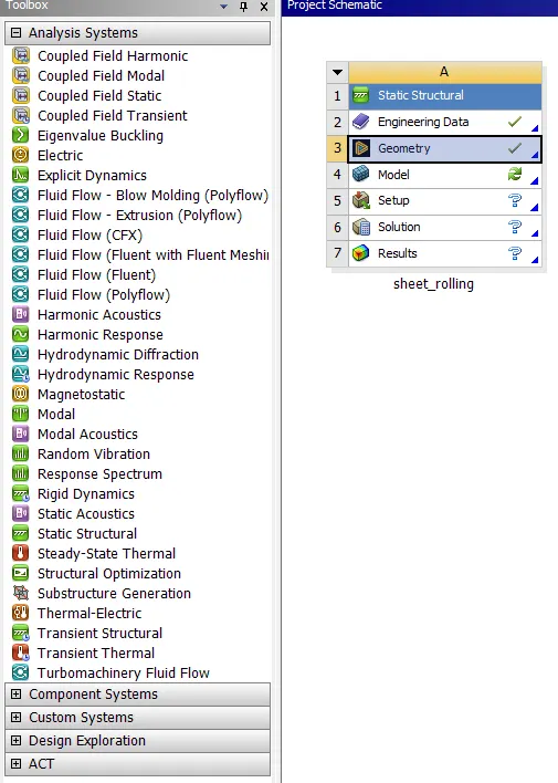
- Now double click on engineering data which is here structural steel as default so as per the question we have to add copper for the sheet.
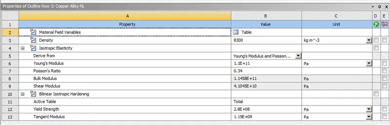
- After that right click on the geometry and import the geometry available in the question. And again right click and select edit in spaceclaim.
- So as per the question we have to increase the length of the workpiece by 60mm and decrease its size on both sides by 8mm,for that i am going to use pull option in spaceclaim.
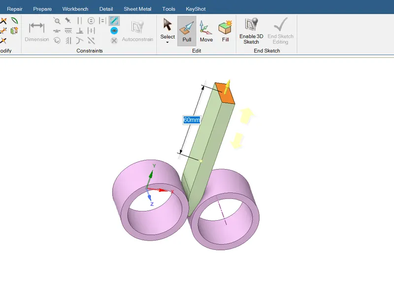
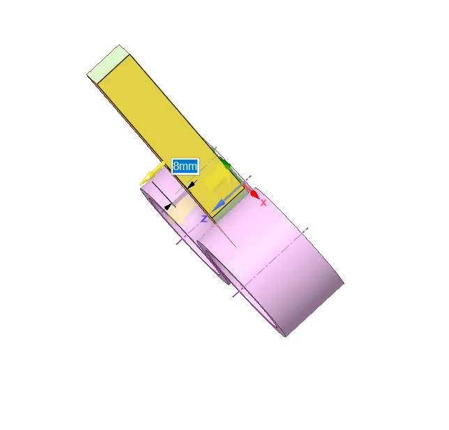
- After that we have to close the spaceclaim and right click on model and click on update,then double click to edit in mechanical.
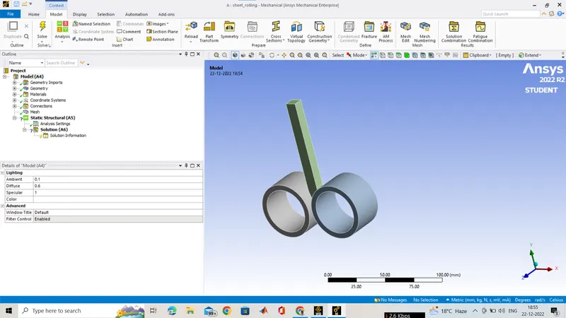
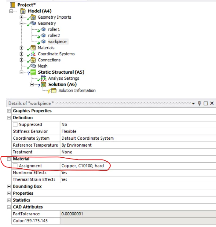
- Now click on geometry and rename it as shown below and change the material of the workpiece to copper.
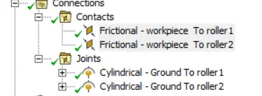
- Now click on connections and make 2 contact between rollers face and workpiece face and 2 cylinderical joints for both cylinder.
- The settings of the contacts are shown below.
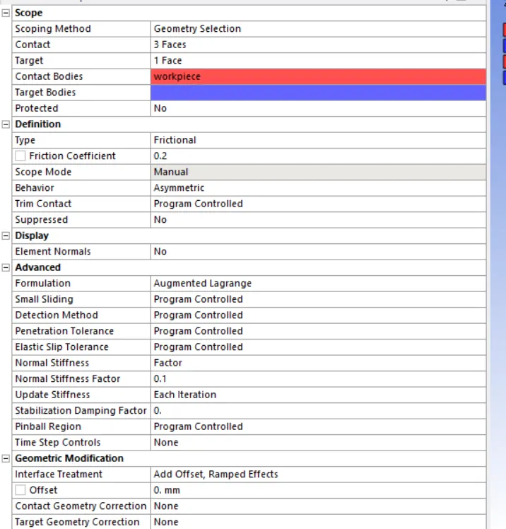
- Now click on the mesh and add one body sizing to the workpiece and element size is 2mm and Face sizing mesh element size 3mm.And it i not exceeding the acadmic version size of nodes and elements.
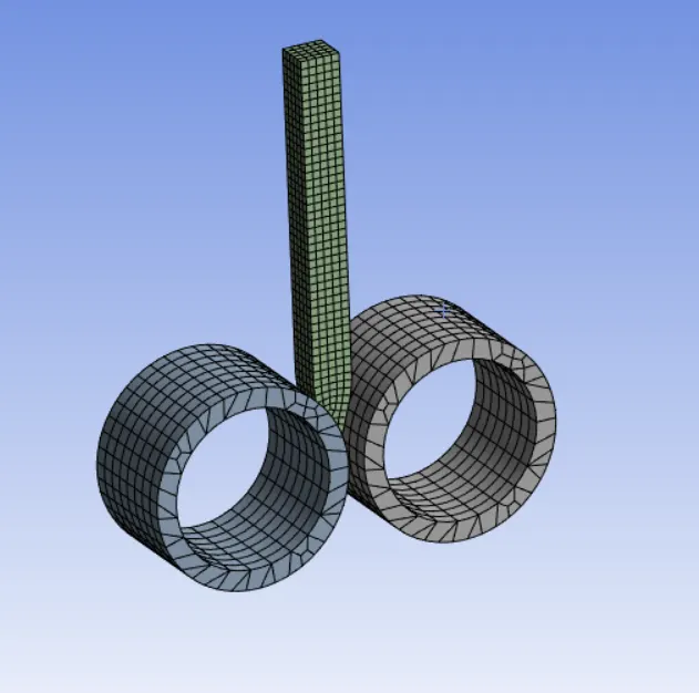
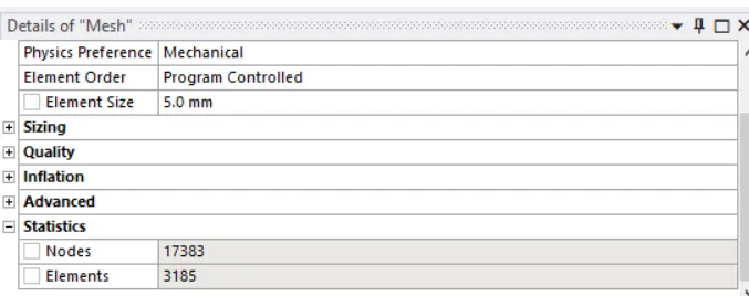
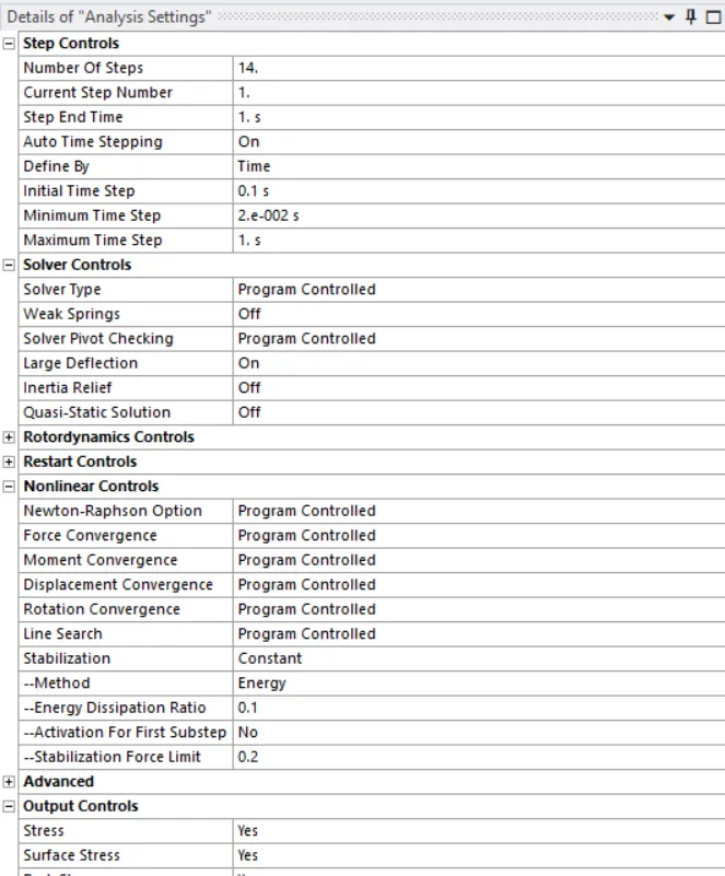
- After that meshing we have to click on analysis setting and make the step into 14 and select all the 14 step and make the large deflection on and in the non linear option stablization to be constant and and energy dissipiation ratio be 0.1.
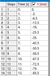
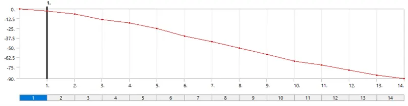
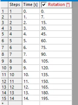
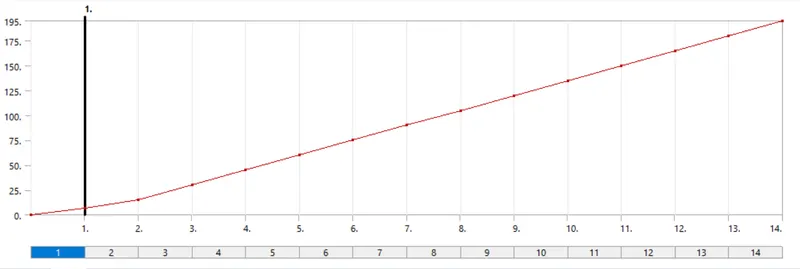
- Then input the boundry condition which is here 3 boundry condition on is displacement of the workpiece in the negative Y direction and in the values in the tabular form. Second and third input are rotational joint both in oposite direction and given the rotational angle in tabular form.
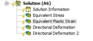
- Now after that in the solution part input all the results.
- Equivalent stress for the whole setup.
- Equivalent Plastic strain for the workpiece.
- Directional Deformation in the Z axis for the workpiece.
Results:
Equivalent stress for the whole setup :
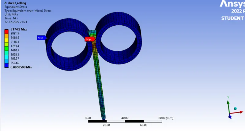
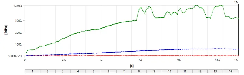
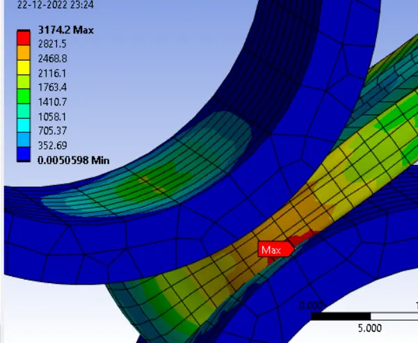
The max stress is comin over the pobe shown upper and the max equivalent stress is:3174.2 Mpa.
Equivalent Plastic strain for the workpiece :
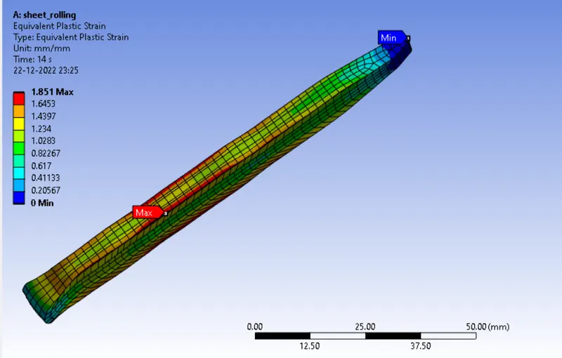
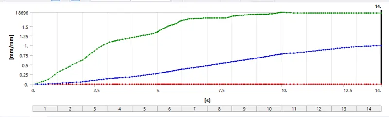
The max equivalent plastic deformation is 1.851
Directional Deformation in the Z axis for the workpiece :
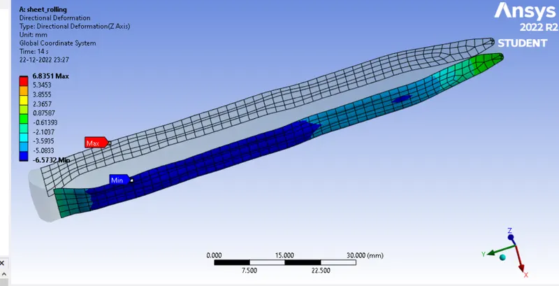
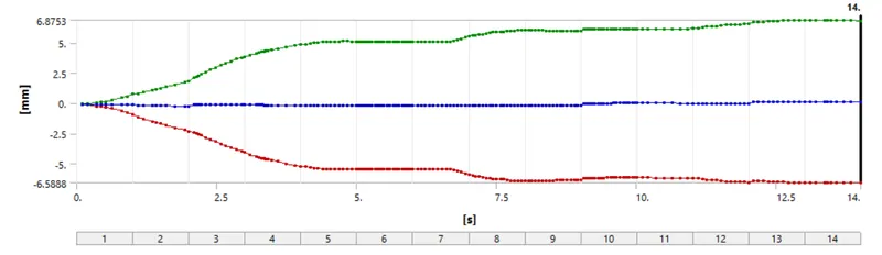
max Directional Deformation in the Z axis for workpiece is 6.8351 mm.
Directional Deformation in the y axis for the workpiece :
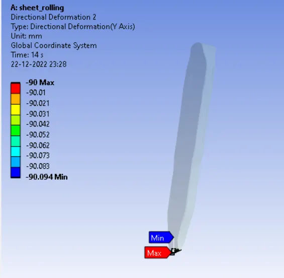
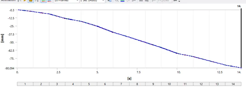
Here in this image shown above you can see that the graph is gone upto 90mm and also in the upper image the tip of the workpice deform max to 90mm so it displaced 90 mm.
Conclusion:
As per the question ask all the results i had manced and the simulation of copper alloy sheet rolling is completed and also it is proved that the displacement of workpiece is 90mm.