Week 3 Sheet metal Bending challenge
AIM:
Sheet metal bending is to be performed for 3 different materials mentioned below. Variation of certain settings is also to be performed and your conclusions are to be added to the report.
OBJECTIVE:
Case 1:Aluminium Alloy 1199( mentioned in the course video), Copper Alloy NL, and Magnesium Alloy NL. Find out the Equivalent stress, Equivalent elastic strain, and Total Deformation in the Y direction and compare the results for the three materials.
Case 2:With the material as Aluminium Alloy, change the friction coefficient to 0.19 and run the analysis as mentioned in Case 1. Compare the results with that in case 1.
Case 3: Refine the mesh on the plate such that it doesn't cross the academic limit. With Aluminium alloy as material, run the analysis as in Case 1 and compare the results.
Case 1:Aluminium Alloy 1199( mentioned in the course video), Copper Alloy NL, and Magnesium Alloy NL. Find out the Equivalent stress, Equivalent elastic strain, and Total Deformation in the Y direction and compare the results for the three materials.
Procedure:
Note: Here procedure for all cases are same, so i am explaining only one and rest of the cases having change in data only.
Start the ANSYS Workbench and double click on static structural and rename it sheet_bent.
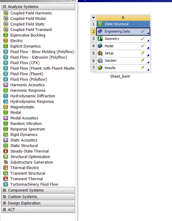
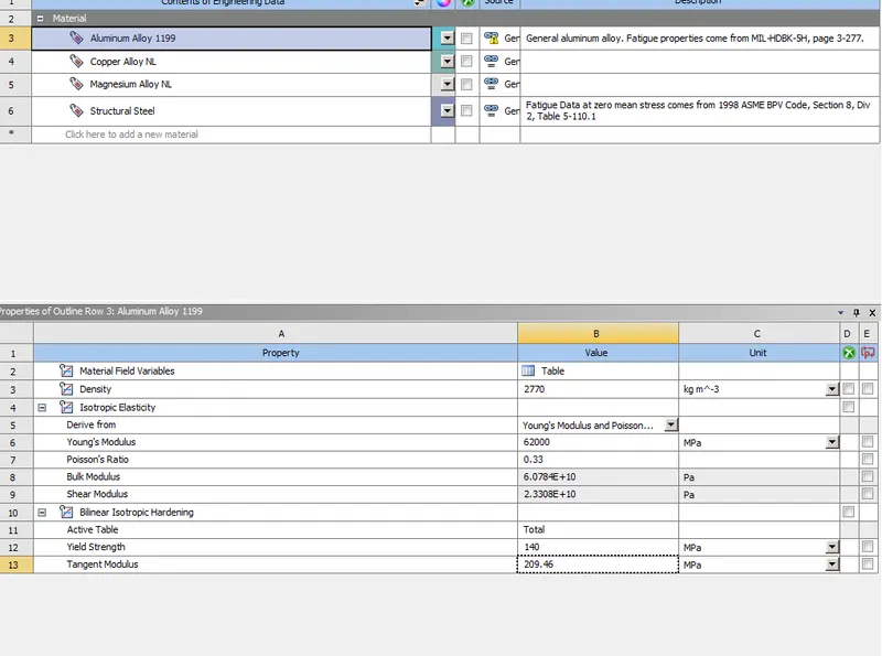
Now double click on engineering data which is here structural steel as default so as per the question we have to add 3 materials from the non linear general material. Aluminum alloy 1199, Copper Alloy NL, and Magnesium Alloy NL as shown below.
After that right click on the geometry and import the geometry available in the question. And here no changes required.
After that we have to right click on the model and click on update. After that double click on the model to edit in mechanical.
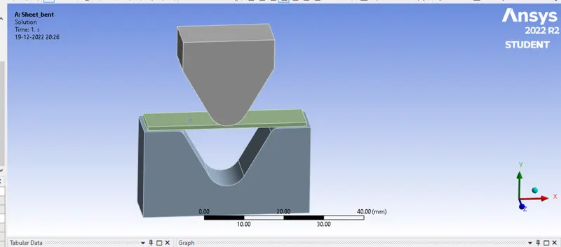
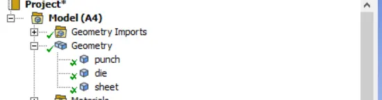
first work is to change the name of the geometry.
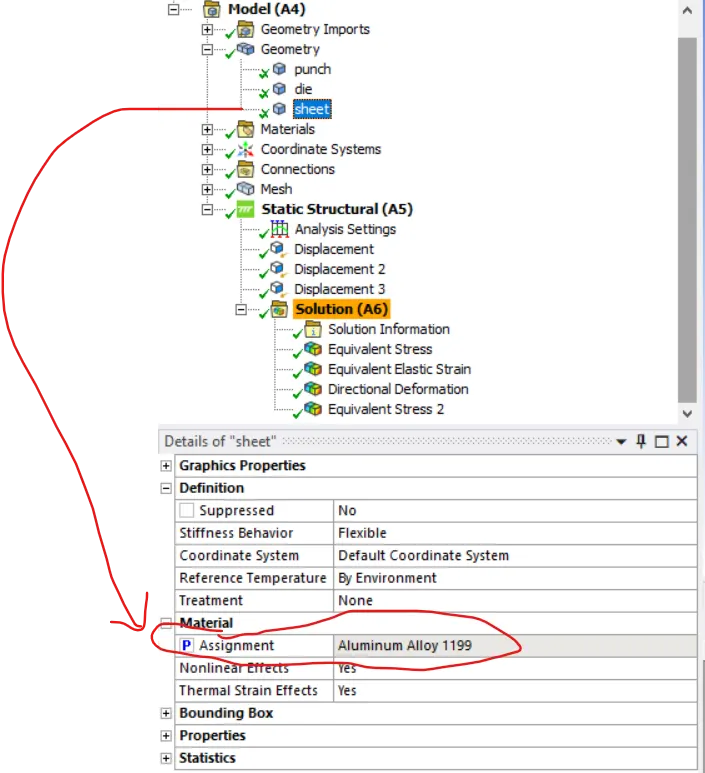
now we have to assign the material for the case one first material is aluminum alloy 1199 and assign this material to the sheet only.
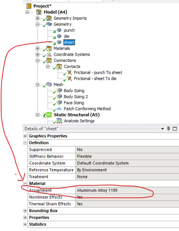
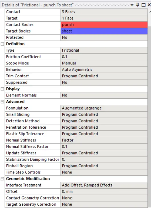
After that we have to assign the contact. in this model only two contact is required. both the contacts are frictonal and one is betbeen puch and sheet and another is sheet and die.frictional coefficient as 0.1 and formulation is augmented lagrange,normal stifness factor is 0.1 and interface treatment is add offset,ramped effect.
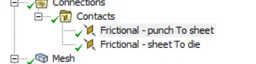
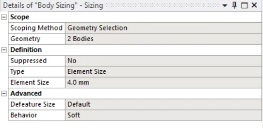
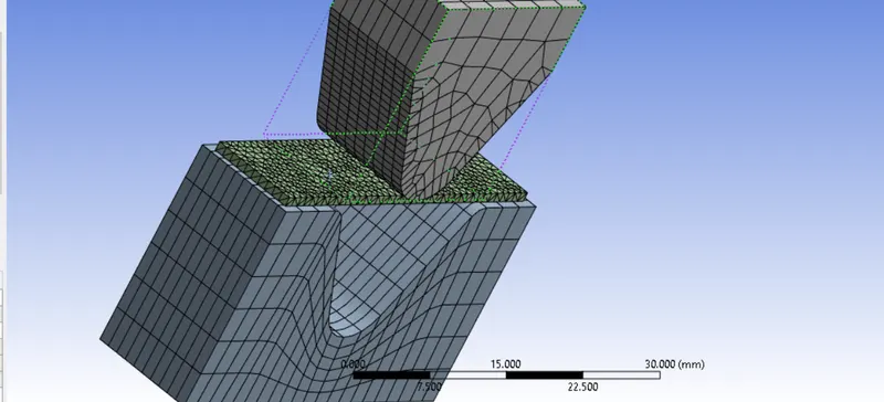
After contacts we move forward to mesh so here we used 2 body sizing and one is face sizing.
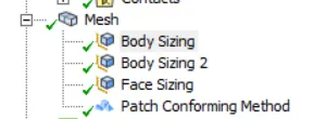
here first bodysizing is used for die and punch where the element size is 4mm.
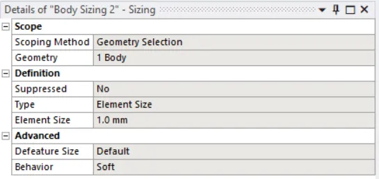
The secon body sizing is for the sheet and here it is of 1mm element.
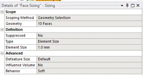
third is face sizing which is applied for thefaces which comes in contact with sheet so the element size is 1mm and finally for the sheet we have chosen the mesh method as tetrahedron.
Now the analysis setting here we have totake the 10 step so the punch hit the sheet in total 10 step and also return back.
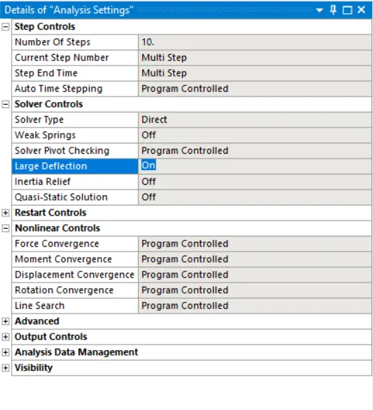
After that we have to give boundry condition.
So here we have to give the displacement in negative y direction, we have 3 displacement 1 is for the punch to move down in negative y direction and the input is given by the tabular form,second displacement is for the sheet where we are fixing the z axis of freedom by giving the tabular data in z axis as zero and lastly we have a displacement for the die at the end of the press move slightly down so we have to give it in -ve y direction tabular form.
all the images are shown below.
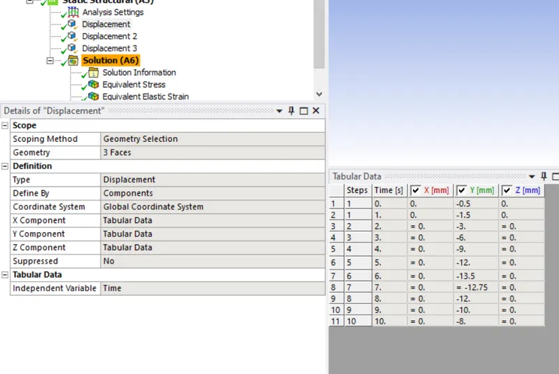
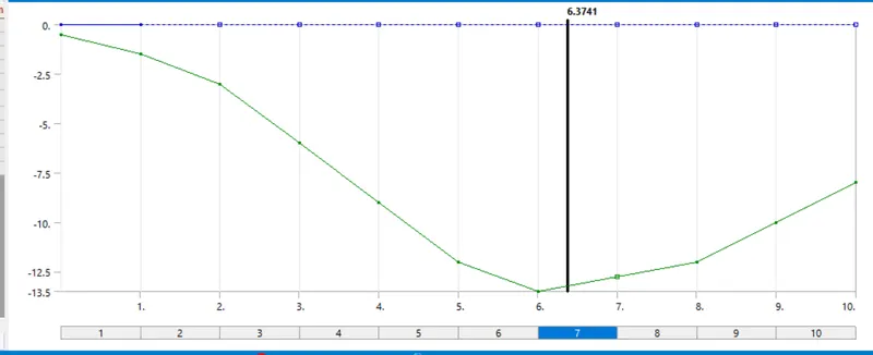
above image is for the punch.
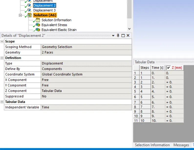
the above image is for the sheet.
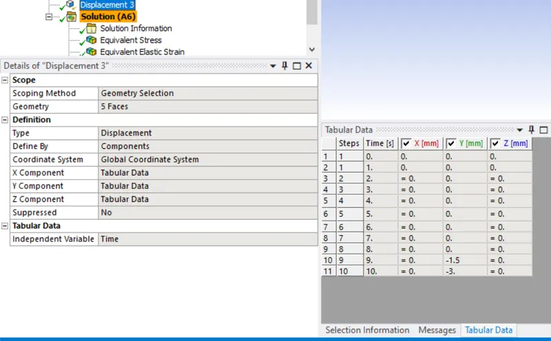
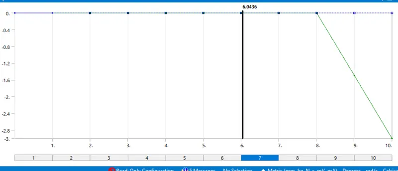
the above image is for the die.
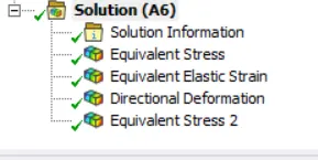
After the boundry condition we have to add what all outputs are required after the simulation so here i added total deformation in y axis which is directional deformation,equivalent stress,von mises strain which is equivalent eleatic strain.
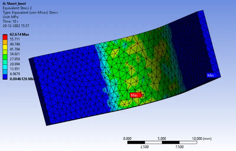
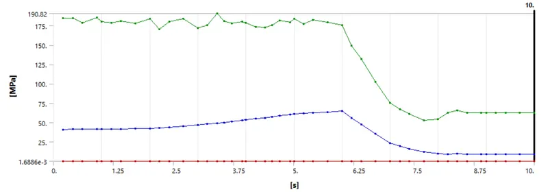
And one more equivalent stress is added for the sheet only.
Results:
Equivalent stress.
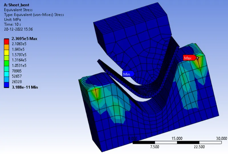
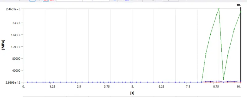
equivalent stress in whole model.
Equivalent strain:
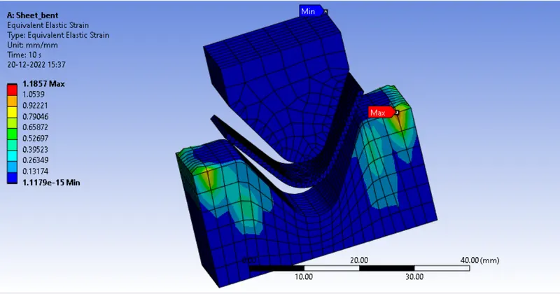
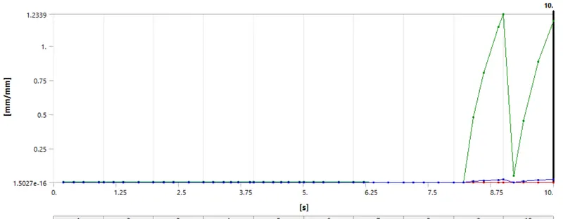
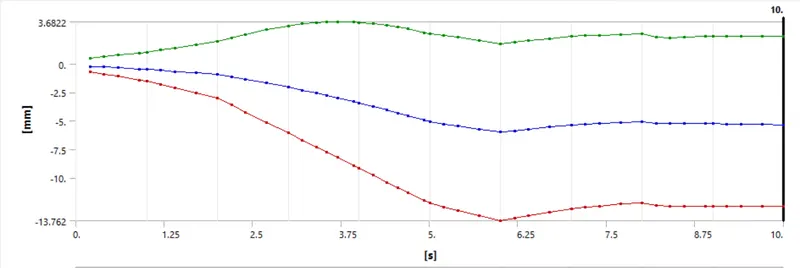
Directional deformation:
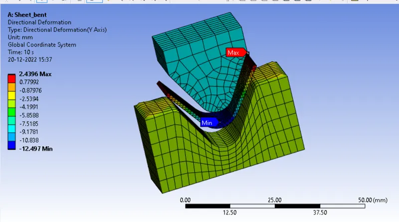
Equivalent stress in sheet:
Now for the same case we have to change the material to Copper Alloy NL and Magnesium Alloy NL.
So for that we use parametre set, to the sheet material, and also the result outputs as shown below.
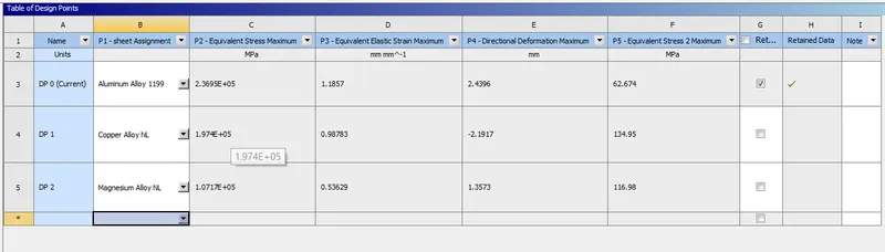
Here we directly check that what all differences will come after changing the material i.e,Copper Alloy NL, and Magnesium Alloy Nl.
Discussion:
Here we can see that after changing material the maximum equivalent stress for whole model is is high in Aluminum Alloy 1199 i,e. 2.369E+05 Mpa.and the stress generated on the sheet only is maximum in copper alloy NL only i,e.134.95 Mpa.
The max elastic strain is highest at Aluminum Alloy 11989 only i.e,1.1857 and lowes value among all three is of Magnesium Alloy NL i.e, 0.53629 .
And the maximum directional deformation is highest among all three is aluminium alloy 1199 i.e,2.43959 mm and lowest at copper alloy NL i.e,-2.1917 mm.
Case 2:With the material as Aluminium Alloy, change the friction coefficient to 0.19 and run the analysis as mentioned in Case 1. Compare the results with that in case 1.
Procedure:
All the steps is same here any only thing i am changing is frictional coefficient i.e, 0.19 so for this also i am going to use parameter set for the frictional co efficient.
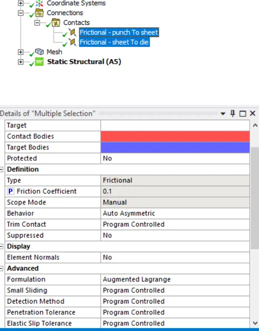
Lets see the result and its comparision.
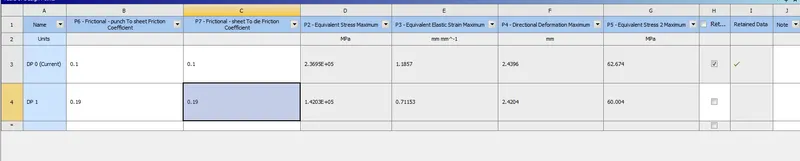
So after changing the frictional coefficient from 0.1 to 0.19 we have differences in results.
max Equivalent stress decreases from 2.3695E+05 Mpa to 1.4203E+05 Mpa.
max Equivalent strain also decreases from 1.1857 to 0.71153.
And directional deformation is aproxx same eqivalent to 2.400mm.
And max equivalent stress induced in the sheet is also decreases from 62.674mm to 60.004mm.
So it is better if we increase the frictional coefficient.
Case 3: Refine the mesh on the plate such that it doesn't cross the academic limit. With Aluminium alloy as material, run the analysis as in Case 1 and compare the results.
Procedure:
here procedure is same we add a perametric set to get the variation.
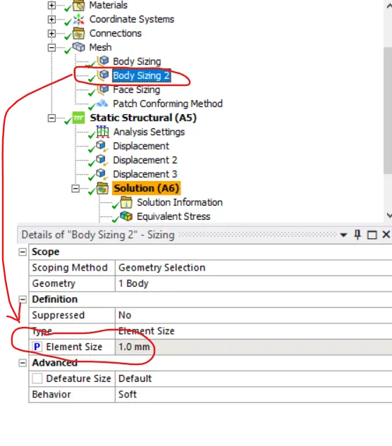
Results of parametr set:

As the academic verson's node count increases to 32000 so here i troed to refine the mesh as low as possible by giving 0.8mm and 0.75mm so the nodes and elements generated at 0.8mm element size is 24188 and no of element is 10061.And the no of node generated at 0.75mm element size is 26114 and the no of element is 11245.
So from the result given above we are decreaasing the mesh size the resut we are getting is more accurate.
Like equivalent stress for whole model is 2.369 mpa in case 1 but at 0.8mm element size it increases to 2.4164 Mpa and at 0.75mm it is 2.405 mpa.so we can see that their is not much difference by decreasing the mesh size further from 1mm the equivalent stress for whole model is not much differ.
If we talk about about equivalent strain at 1mm mesh size it is 1.1857 but at 0.8mm and 0.75mm mesh size it is aprox same i.e,1.200
And the directional deformation is slightly deduced at 0.8mm from 1 mm but aproxx same at 0.75mm.
And the equivalent stress induced at sheet is vairying from 62.674Mpa at 1mm mesh size to 57.177 Mpa at 0.8mm mesh size and again it increases to 65.385Mpa at 0.75mm mesh size.
So we concluded that 0.8mm mesh size is good for all over and if we decrease further the results are same aproxx.and also the solving time will increase.