Project 1 - 2D meshing on the instrumental Panel
AIM:
For the given component, check for the geometrical errors and mesh with the given element Quality criteria. After meshing the component the thickness has to be assigned.
Write a detailed report on your meshing process and also mention which method you used to extract the mid-surface along with the reason.
|
S.No |
Quality Criteria |
Value |
|
1 |
Target/Average length |
4 |
|
2 |
Minimum Length |
2 |
|
3 |
Maximum Length |
6 |
|
4 |
Aspect |
3 |
|
5 |
Warpage |
15 |
|
6 |
Skewness |
45 |
|
7 |
Jacobian |
0.7 |
|
8 |
Minimum Quad Angle |
45 |
|
9 |
Maximum Quad Angle |
135 |
|
10 |
Minimum Tria Angle |
30 |
|
11 |
Maximum Tria Angle |
120 |
|
10 |
Tria Percentage |
15 |
PROCEDURE:
First we are going to import the geometry,and check or the geometry cleanup or topo require or not.
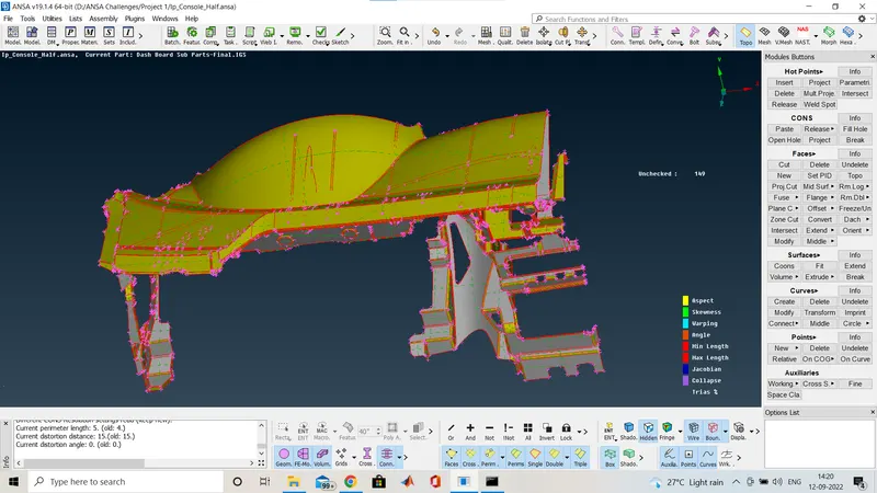
- The image given below is the CAD geometry after importing and this geometry is without topo cleaning or geometry cleanup.
- And the model is opened in toto mode .
- Here first we have to do topo.
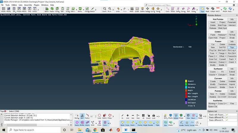
After topo it looks like this.Now i am going for the geometry check.
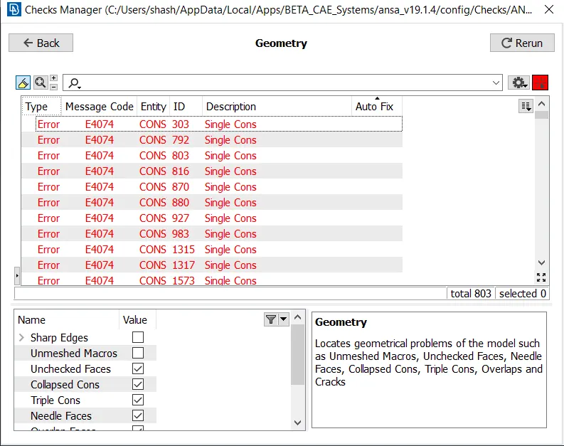
- here we are going to open the geometry check for the geometry cleanup.we can clean the geometry one by one also manually and ansa has a feature to clean it in once automatically.
- After doing automatic geometry fix again some crack faces and single cons are there.So we will do manually.
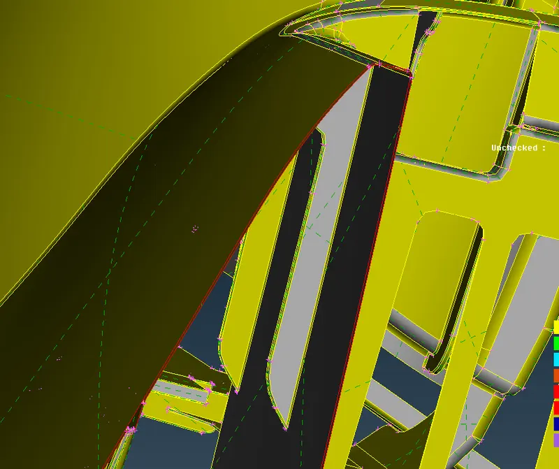
These areas having open volume geometry so manually we create the surface using TOPO Deck>Faces>New
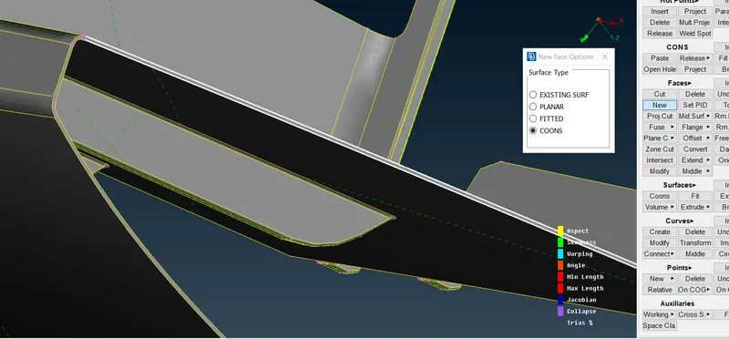
This is how we created the face using this option and in the same way we go for all.
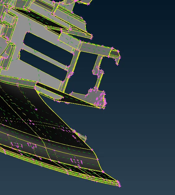
See here hall faces are filled with new surface.Now again check for the geometry.
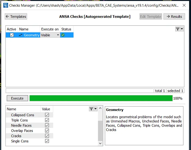
Here you can see that no geometry cleanup required. now we go for the mid surface extraction and then do the meshin.
But here i am using the casting option available in TOPO deck>Faces>mid surface>casting
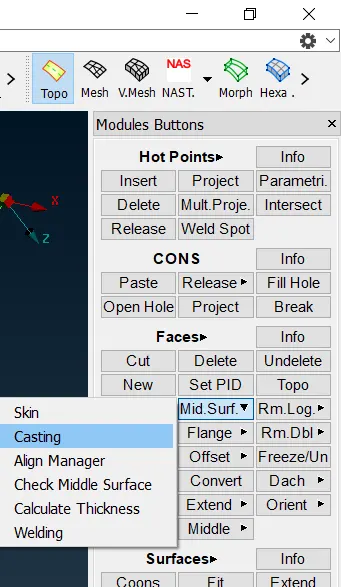
- The casting option is mainly used for the automated FE generation.It basically used for the bigger component for saving the time,like manually we go for first mid surface extraction and then for the shell mesh but it directly gives us the FE but the FE is no perfect so we have to improve it but over all time of generating FE will reduces so here i am showing you how to go with casting option.
- But before we go for the casting here we have a huge component so first we have to divide it into different part as in different PID because if we go for the whole component ANSA crash some time it can't handle the huge part at once.
- So i am going for the plane cut option available in TOPO deck>Faces>Plane cut>single.
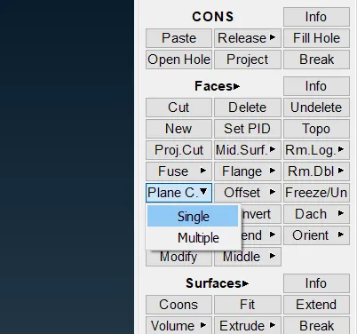
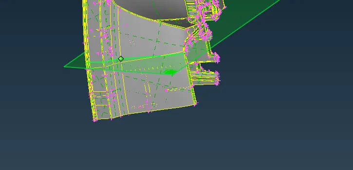
- This is how we have to select the area and made the cut
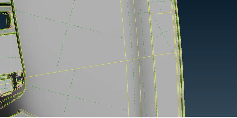
Here you acn see i amde the cut there and now this is how we have to split the part into different section put it inot different PID.
After cutting i am assigning the pid for this part using SET PID option in TOPO Deck>Faces>Set PID.
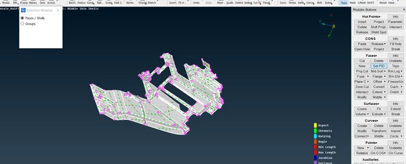
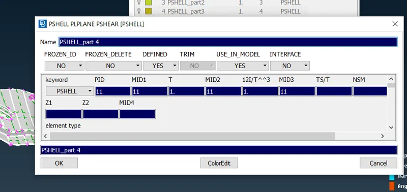
This is how you have to select the face and give the middle click and and a window will popup like shown below and we have to give the name and thickness to the part but here i am jst keeping it in different PID not assigning thickness to it the ansa automatically gives the thickness as 1.
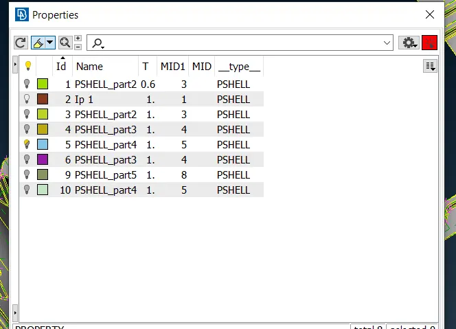
Here we assigned different part and now we will go for casting option.
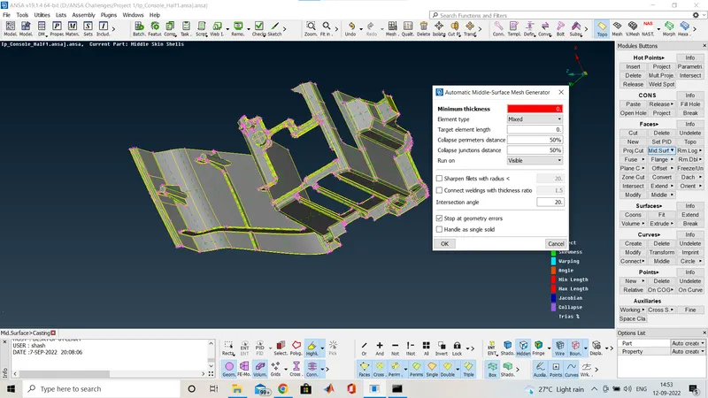
When you go for the casting a window will popup like this.
So hre we will give the minimum thickness here we have measured it the minimum thickness is 0.6
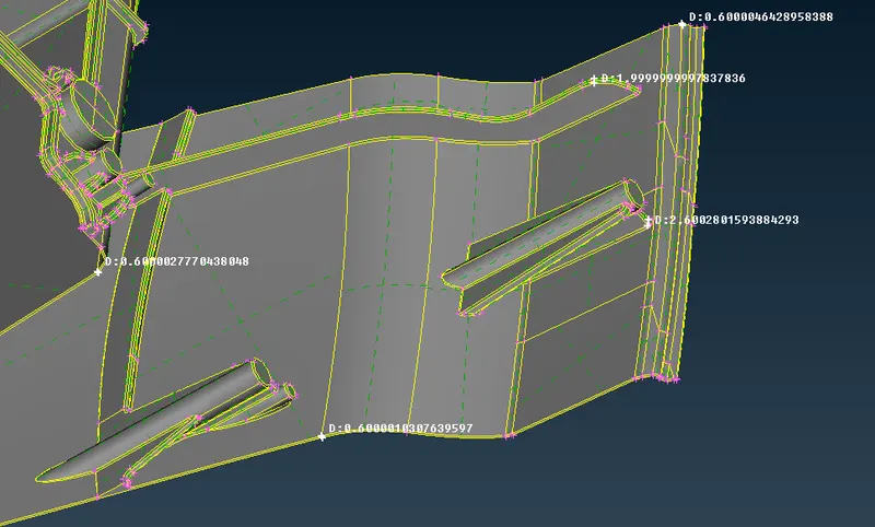
And as per the quality criteria we have the target/average lengeth is 4. so i had given it and hit ok.
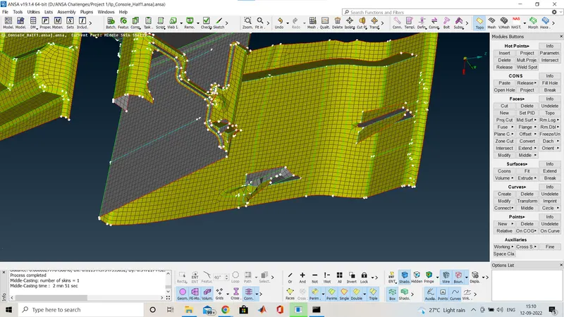
- After processing we will get the the FE and that is not perfect some areas are totally runed As you can see above and also having quality issue.so now for improving this we are going to use the align manager.
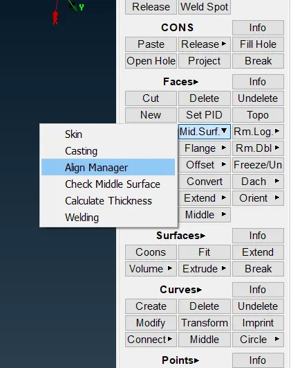
- So basically align manager stores the whole process like how the FE is generated each process and by using that we will edit or creat new surface and improve the FE.align manager is available in
TOPO deck>Faces>mid surface>Align manager.
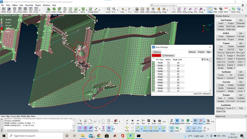
After opening align manager the window will looks like above,there you can see the surface is noot good at the marked area.now we will go to the align manage window and in area which is highligted in red and find that area which is not good by selecting that area that process will highlight in blue color as shown below.
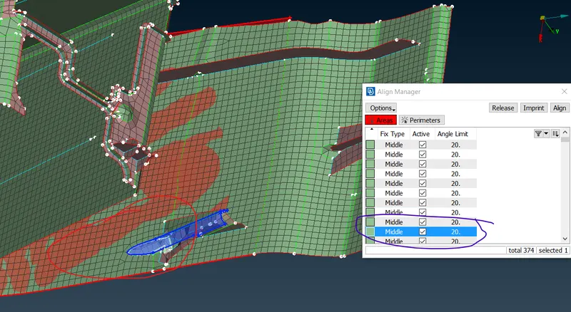
Here the red area is the distorted area and the blue mark in the allign manager window is the process by using which surface we got that so i am going to edit that and make it in the right way.
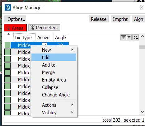
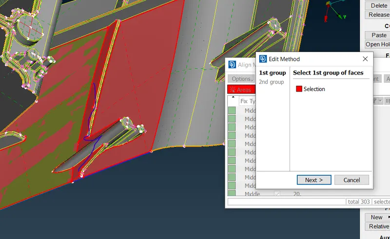
The blue mark areas are over selected so we have to deselect them then select the other side which is blue in color and then hit middle mouse click and we will get the improved FE as shown below
Here the red area is the distorted area and the blue mark in the allign manager window is the process by using which surface we got that so i am going to edit that and make it in the right way.
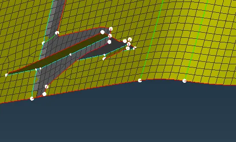
This is how you will get that and also for the features which is clyndrical in shape we will going to creatre those area i am showing it below.
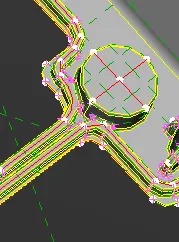
here is a cylinderical surface so now i am going to capture it in FE.
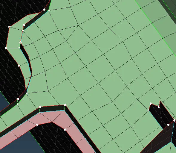
you can see here in FE nothing is catured or sometimes the fillet lines are just captured so now i am going to create it,for that we will go to parent geometry and take the middle curve like shown below using TOPO Deck>Curves>Create.
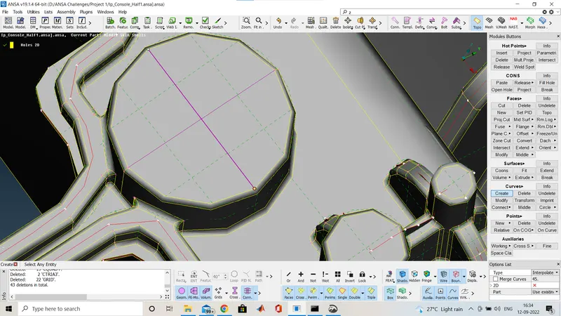
Now we had created the curve and now off the faces and project this curve on the FE by using MESH Deck>Shell Mesh>project as shown below.
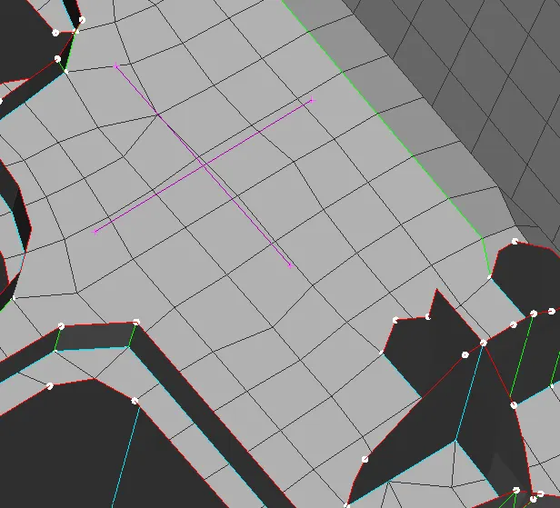
When i off the geometry the curve is shown like this, and now we project to the FE,when we select the project option a window will appear like below.
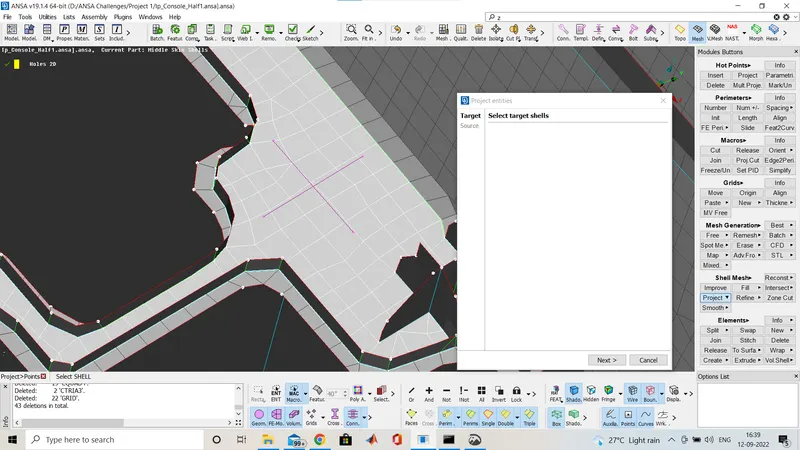
I had selected the target where i have to project it.After clicking next you have to select the curve as shown below.
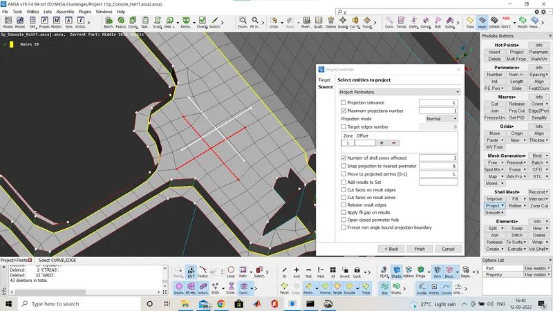
Then do middle click an that is project in the FE as shown below.
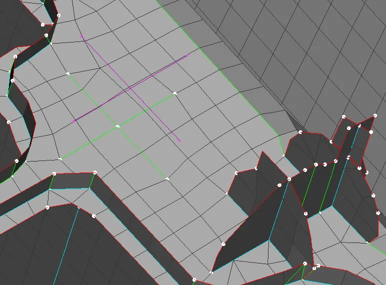
Now by using fill option in the MESH Deck>Shell Mesh>Fill we will create the FE between both the fillet and the Curve.
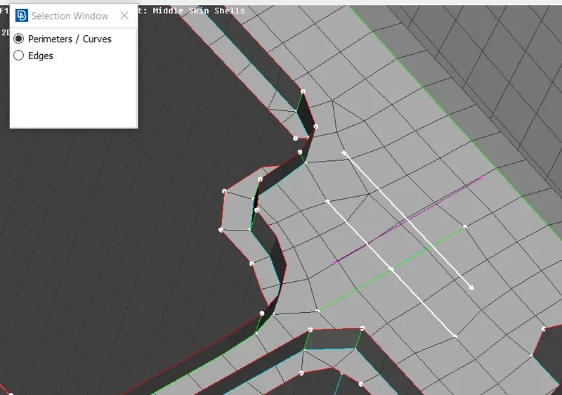
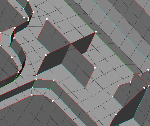
See the face is ceated now i do the intersection In the TOPO Deck>Faces>Intersection so that both are connected to each other.
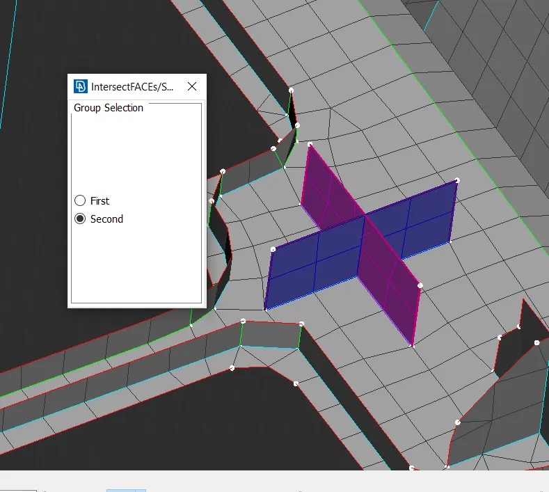
After doing middle click you can see that both are connected.we got the FE for that part.
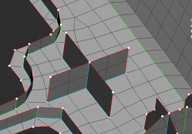
We have a lots of functions in the align manager and it is impossible to show each and every here so i jst show some of them and like that i algned all the surface and using the casting option i got the FE then after that for the quality we use improve option or smooth option in MESH Deck>Shell Mesh>improve/smooth.
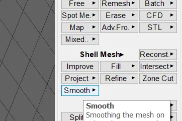
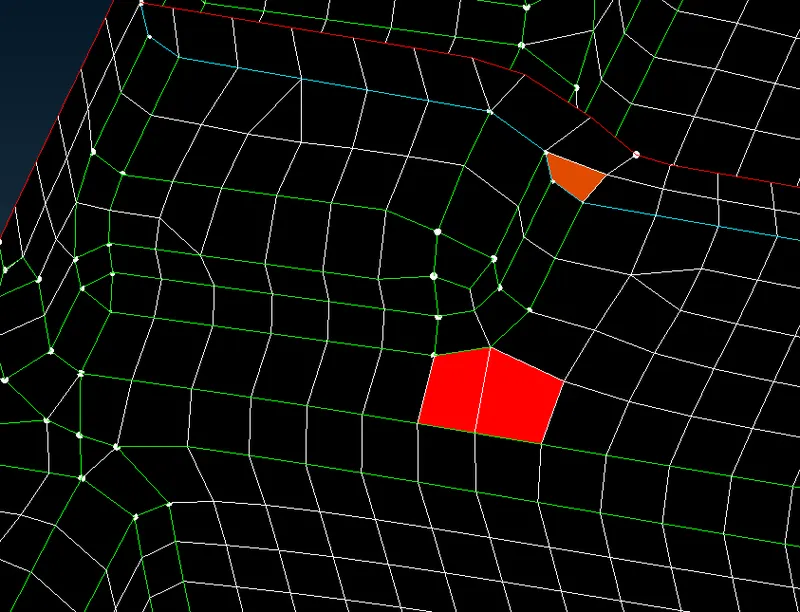
Here we have quality issue of min/max length so by doing smooth at that place we will get the improved mesh.
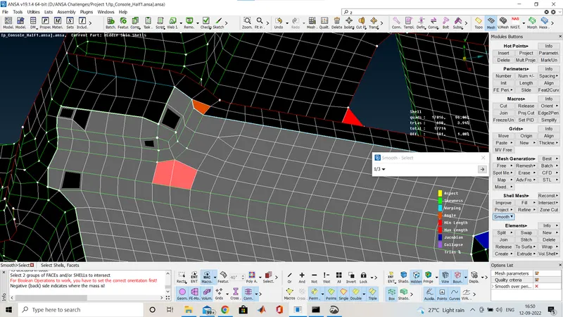
Select the are and do middle click 2 time you will get he smooth mesh flow.
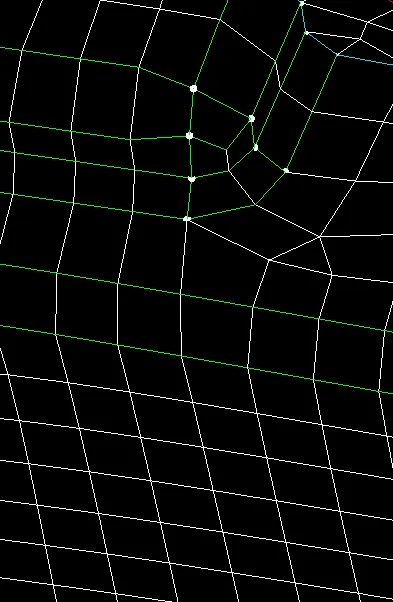
See the mesh is now smooth,in te same way we have to select the the are and use the improve and the smooth option wherever we require to improve the mesh flow .
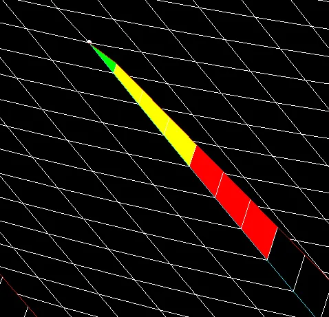
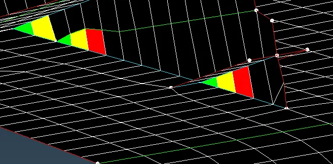
We have some off element becuse of triple cons it is not possible to clear that.
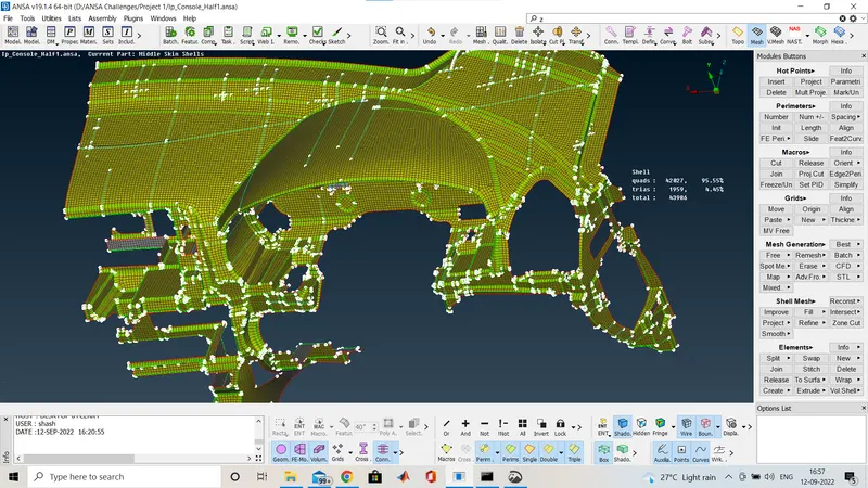
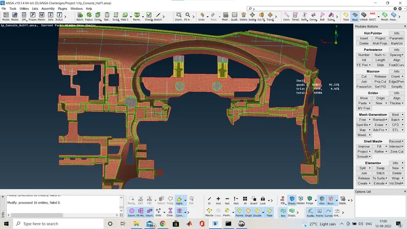
This is how the complte FE of the component looks like.
At last we have to assign the thicknes for different features with various thickness in the different PID.
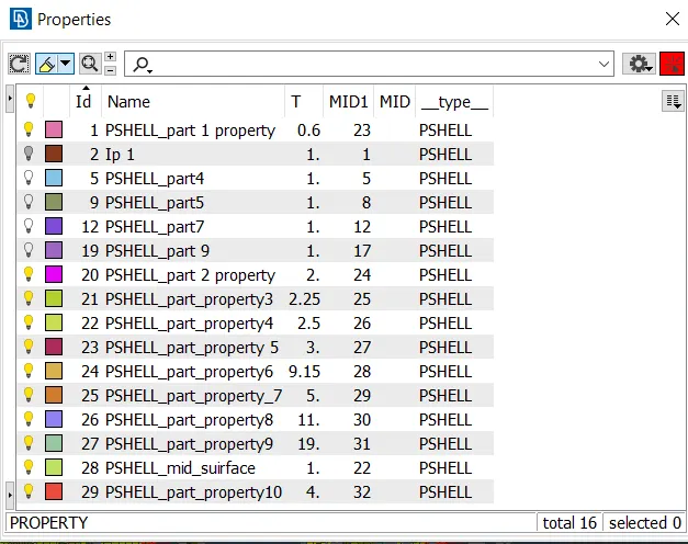
i ahd assigned it by measuring the thickness from the parent geometry.