Project 1 Mechanical design of battery pack
AIM: Mechanical design of battery pack for ANR26650M1-B cell
Objective :
- Design a Battery pack capacity of 18 kWh.
- Prepare a detailed battery pack drawing along with its enclosure by using ANR26650M1-B cell . State your assumptions.
Theory:
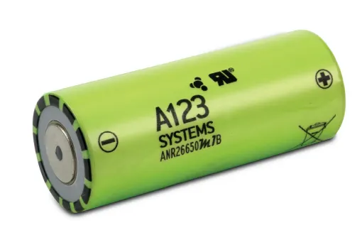
Nanophosphate® High Power LithiumIon Cell ANR26650M1-B
A123’s high-performance Nanophosphate lithium iron phosphate (LiFePO4) battery technology delivers high power and energy density combined with excellent safety performance and extensive life cycling in a lighter weight, more compact package. Our cells have low capacity loss and impedance growth over time as well as high usable energy over a wide state of charge (SOC) range, allowing our systems to meet end-of-life power and energy requirements with minimal pack oversizing.
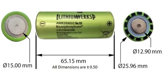
CELL DIMENSION:
Technical specification:
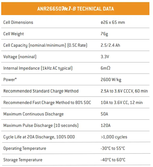
- Nominal voltage of cell is given as 3.3v
- Cell capacity is given as 2.5Ah
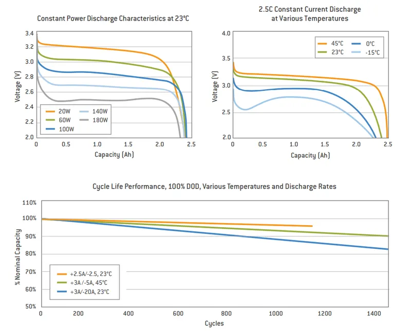
- First graph is all about the constant power discharge characteristics,where voltage with respect to capacity.
- So there 20w discharge where the voltage start from aproxx nominal voltage 3.3v and discharge cutoff at 2v and uses 2.4/2.5ah capacity
- And if you see about the highest power 180w discharge curve it starts from aproxx 2.8v and reaches cutoff voltage before the actural capicity.
- Second graph is 2.5c constant current discharge at verious temperature,where voltage with respect to capacity.
- So here at 45 c it discharge from normal range aproxx starts discharging from the 3.3v and reaches cutoff voltage 2v at 2.5Ah capacity.
- And the same discharge current if operates at -15c you can see that in the graph the line starts at 2.7v and reaches faster at cutoff voltage and uses less capacity.So whether you discharge at same current but the result is showing different capacity it is because of different operating temperature.
- The third graph is of cycle lype performance,at verious temperature and discharge rate,the capacity with no of cycle.Here at 2.5A/-2.5A discharge current and operating at 23c.the capacity remains at aproxx 95% after 1200 cycle
- And in the same plot at the +3A/-20A dicharge current operating at 23c temperature the capacity is decreased to aproxx 82% after 1400 cycle.
Now Assumption And calculation of parametres for the battery pack design:
- Now we understand the whole characteristic or parametres of the cell from above expation.
- So here we are assuming the battery we are designing for the Electrical vehicle is driven by the E-Motor,operating voltage of 200v
Now,the total pack energy consumption is 18KWh = 18000Wh
- The total no of cells in series = Total voltage demand/voltage of each cell =200/3.3=60.60= 60 cells in series
- Total capacity requirment of the the pack = Total energy/voltage of the moter=18000/200 = 90Ah
- Number of cell in parallel = Total pack capacity/capacity of each cell = 90/2.5 = 36 cells in parallel
- So the battery module is in the form of 60S36P.
- Total no. of cells in the pack = no. of cells in series* no. of c ells in parallel = 60*36=2160 cells used in total pack.
- Total weight of the battery pack = each cell weigh * no. of total cell = 0.076*2160=164.16kg ( @cell weight is taken from the specification provided above i.e, 76g = 0.076kg)
- Here we have got the aproxx weight of pack about to 164kg becaue we are not assuming lots of parametre i.e, material weight used for outer package,module housing,thermal material,etc having lots of aspect.
- Total internal impedance of the pack = each cell internal impedanc * no.of total cells = 0.006*2160=12.96ohm ( @cell impedance is taken from the specification provided above i.e,6mohm=0.006ohm)
- Volume of each cell = pi*R^2*h = 3.14*(0.013)^2* 0.065=0.0000344929m^3. ( dia = 26mm,height = 65mm given in the specification)
- Total volume of the pack = no of total cells*volume of single cell = 0.0000344929*2160=0.074504664m^3
-
Volumetric energy (Wh/m^3) = Single Cell Energy / Volume of each cell
= 8.58 Wh / 0.03451 m^3
= 248.62 Wh/m^3
-
Gravimetric energy (Wh/kg) = Single Cell Energy / Single Cell Mass
= 8.58 Wh / 0.076 kg
= 112.89 Wh/kg
- We have lot of aspect to calculate i.e, Energy, density,specific energy ,Specific power,Power density,etc but we can exactly calculate all that parametre based on assumption,we need lots of data for calculation all data.
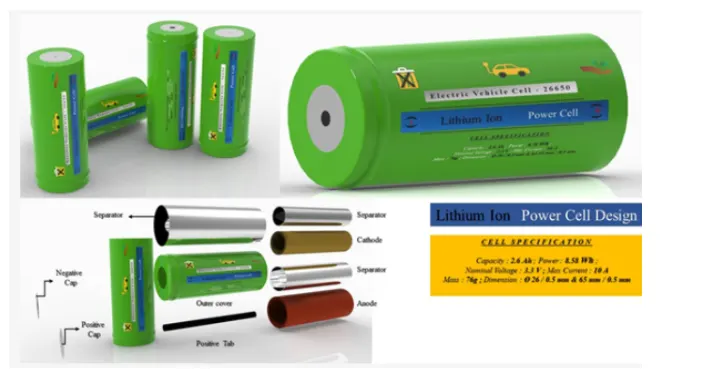
THE ARRAGEMENT DESIGN OF SINGLE CELL IS SHOWN BELOW:
Batteries can be connected in a mixture of both series and parallel. This combination is referred to as a series-parallel battery. Sometimes the load may require more voltage and current than what an individual battery cell can offer. For achieving the required load voltage, the desired numbers of batteries are combined in series to achieve the current needed, and these series combinations are connected in parallel.
THE suitability of joining methods to build battery packs using cylindrical cell is shown in figure:
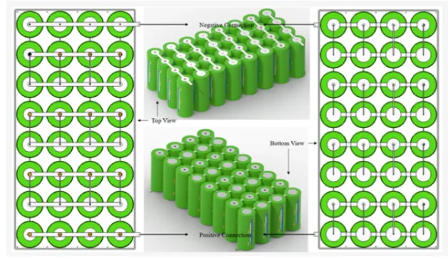
- We have a lot of things for joining like Copper, nickel, nickel-plated steel, nickel-plated copper, aluminium
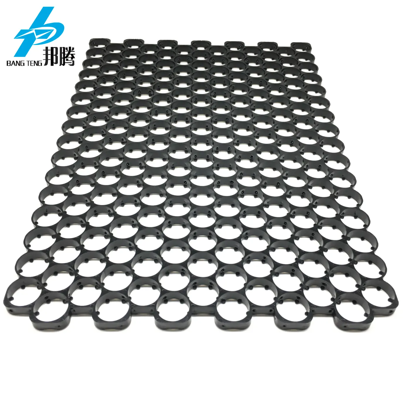
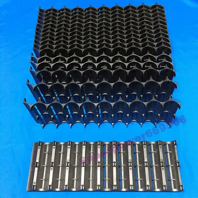
Cell Holder:
A battery holder is one or more compartments or chambers for holding a battery. For dry cells, the holder must also make electrical contact with the battery terminals. For wet cells, cables are often connected to the battery terminals, as is found in automobiles or emergency lighting equipment.
A battery holder is either a plastic case with the shape of the housing moulded as a compartment or compartments that accepts a battery or batteries, or a separate plastic holder that is mounted with screws, eyelets, glue, double-sided tape, or other means. Battery holders may have a lid to retain and protect the batteries or may be sealed to prevent damage to circuitry and components from battery leakage. Coiled spring wire or flat tabs that press against the battery terminals are the two most common methods of making the electrical connection inside a holder. External connections on battery holders are usually made by contacts with pins, surface mount feet, solder lugs, or wire leads.
Where the battery is expected to last over the life of the product, no holder is necessary, and a tab welded to the battery terminals can be directly soldered to a printed circuit board.
Here i am esplaining about Nikel strips:
Nickel strip is generally used in battery building. Its due to its efficiency of usage in spot welding and soldering as well its high corrosion resistance over time. It has good properties and excellent resistance to many corrosive environments. The pure nickel will never get rust after it applied to battery packs. It won’t affect the current transfer between batteries.
Pure nickel strips are the material you want, but many vendors swap out it for nickel-plated steel strips, which are poorer and have greater resistance – not suitable for most battery projects.
we give 100% pure nickel strip. We verify all of our strips to assure that you are getting the high-quality pure nickel. It also solder incredibly quickly, so you can weld them onto your existing busbar connections to raise the supply of current you can pull through the busbars. The benefits are nearly limitless.



These are all nickel strips.
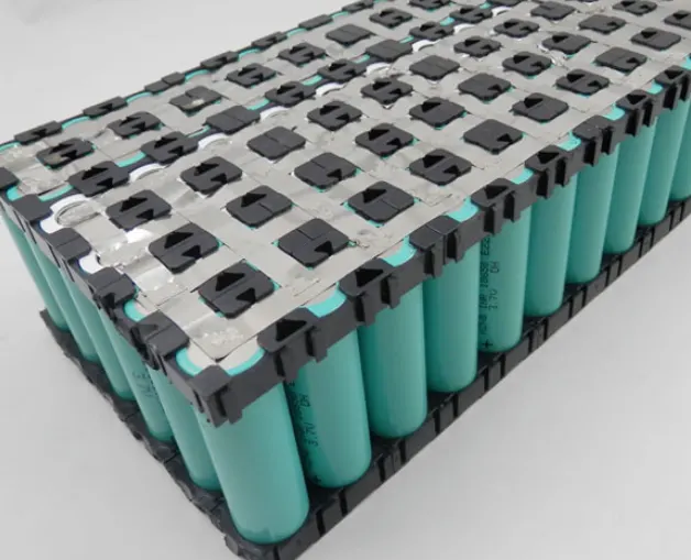
This is how we join by strips in parallel or series.
Module:
When it comes to battery modules, two other words often come to mind: battery cell, battery pack. In fact, battery is a generic term for all three, while battery cell, battery module and battery pack are different forms of batteries in different stages of application. The smallest of these units is the battery cell, several cells can form a module, several modules can form a battery pack by adding BMS and other management systems. Therefore, we can understand the battery module as an intermediate product between the battery cell and the battery pack. When multiple battery cells are packaged together in the same housing frame and linked to the outside through a uniform boundary, this makes up a battery module. It consists of a series-parallel combination of cells, the structure of which must play a role in supporting, fixing and protecting the cells. Whether it is able to fix the cell position and protect it from performance-damaging deformation, how to meet the temperature control of the cell, etc., will be the criteria for judging the merits of the battery module.
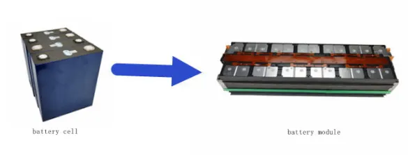
Battery Module means a combination of components of a Battery System that includes at least the following components: a Battery Cell, battery management electronics for Battery Cell balancing, voltage and temperature measurement, and connectors.
Thermal management :
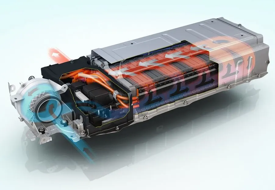
The Battery Thermal Management System (BTMS) is the device responsible for managing/dissipating the heat generated during the electrochemical processes occurring in cells, allowing the battery to operate safely and efficiently.
Keeping EV batteries cooled is the most common thermal management concern. However, batteries used in cold climates often benefit from being heated when temperatures fall. When undergoing fast charging or extra fast charging (XFC) batteries may need additional levels of cooling. This FAQ first considers various active and passive cooling technologies for EV batteries. It then looks at the special challenges facing EV drivers in cold climates such as Alaska. It closes with a brief look at battery thermal management system (BTMS) design challenges to overcome before XFC can become a reality.
An effective BTMS is required to maintain EV batteries within upper and lower temperature boundaries. If the batteries get too hot or too cold, their performance can be diminished, and they can experience permanent damage. Designers can choose between a variety of passive and active cooling technologies to manage the thermal environment of EV batteries. In the longer term, higher-performance BTMS will be required to enable the use of XFC technology.
Battery Enclosure:
Design of an enclosure or container for the battery centers around two concerns: proper selection of materials and design for adequate heat transfer.
The most common battery enclosures are made from plastic materials that are resistant to alkaline solutions and have a high impact strength. Metal housings are sometimes used, but metal requires careful design and assembly to avoid shorting of the cells in the battery pack. Aluminum is not recommended for enclosures because if cell leakage does occur, the electrolyte will react with the aluminum.
The battery enclosure may also have a significant impact upon battery life if not designed properly to prevent the cell's temperature from rising significantly in overcharge. Good battery form factor allows for air movement around cells to help reduce temperature rise in overcharge. As shown in Figure 3-77, a four-cell stick (cells connected end-to-end) has a significantly greater surface area for heat dissipation and therefore lower overcharge temperature than would four cells in a square configuration.
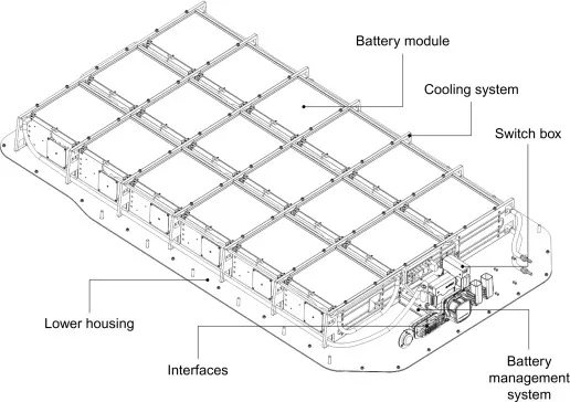
Design Benefits:
• Up to 50 percent lighter than an equivalent steel design
• Best-in-class mass energy density at more than 160 watt-hours per kilogram, an extremely efficient design for OEMs and Tier 1 battery pack manufacturers.
• Accommodates all battery cell types and is designed particularly for battery electric vehicles with larger power packs such as pick-up trucks, sport utility vehicles and crossovers.
• Most cost-effective aluminum solution for mass production electric vehicles when compared to aluminum extrusion and casting-intense designs.
• Low price premium on $/kg saved compared to equivalent steel designs at substantially lower weight.
Final Battery pack: