Project - 2 - Meshing on the suspension Assembly
AIM:
For the given assembly, check for the geometrical errors and mesh with the given element Quality criteria. After meshing the component the thickness has to be assigned for mid surfaces. Use tetra elements to model non-uniform thickness components. Also use Appropriate connections to connect the component as suggested in the Project-2 video (Use PBAR elements to model suspension spring). At last perform Symmetry command to reflect the half finished model to the other side.
Write a detailed report on your meshing process and also mention which method you used to extract the mid-surface along with the reason.
Quality Criteria for Surface Meshing of Tyre and Rim (Element type: Tria) :
|
S.No |
Quality Criteria |
Value |
|
1 |
Target/Average length |
6.5 |
|
2 |
Minimum Length |
5 |
|
3 |
Maximum Length |
10 |
|
4 |
Skewness |
45 |
Quality criteria for Surface Meshing of Non Uniform thickness components other than Tyre and Rim (Element type: Tria) :
|
S.No |
Quality Criteria |
Value |
|
1 |
Target/Average length |
4 |
|
2 |
Minimum Length |
2 |
|
3 |
Maximum Length |
6 |
|
4 |
Skewness |
45 |
Quality Criteria for Volume meshing of all Non Uniform thickness components (Element type: Tetra Elements):
|
S.No |
Quality Criteria |
Value |
|
1 |
Tet-collapse |
0.2 |
Quality criteria for Mid surfacing of Uniform thickness part which has thickness less than 5 mm (Element type: Mixed elements) :
|
S.No |
Quality Criteria |
Value |
|
1 |
Target/Average length |
4 |
|
2 |
Minimum Length |
2 |
|
3 |
Maximum Length |
6 |
|
4 |
Aspect |
3 |
|
5 |
Warpage |
15 |
|
6 |
Skewness |
45 |
|
7 |
Jacobian |
0.7 |
|
8 |
Minimum Quad Angle |
45 |
|
9 |
Maximum Quad Angle |
135 |
|
10 |
Minimum Tria Angle |
30 |
|
11 |
Maximum Tria Angle |
120 |
PROCEDURE:
- First we have to import the geometry.
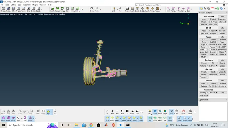
After importing the geometry we go for the geometry check. and here as you can see blow.
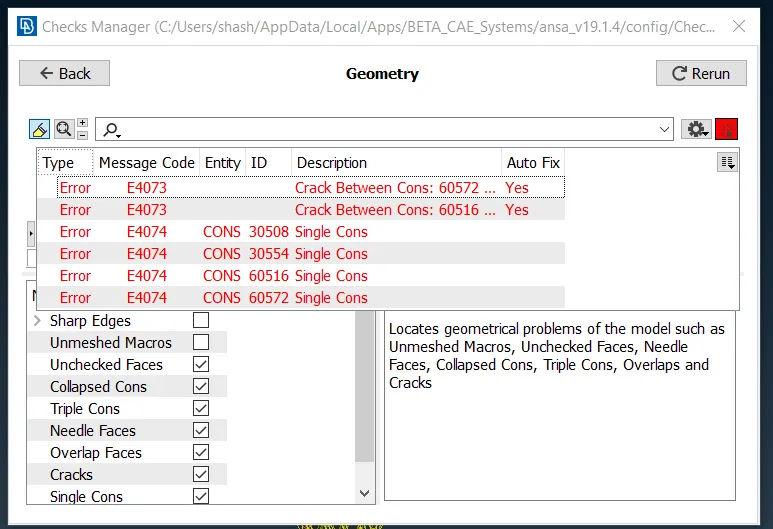
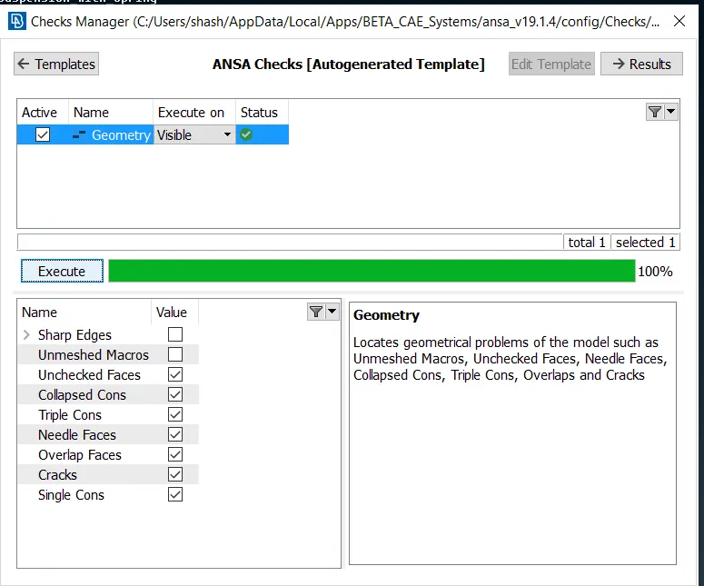
I got some gemorty isse i go for the auto fix and after clearing geometry you can see below i have no geometry issue.
Now after the geometry cleanup we have to go for the meshing so before that as it is a very huge component so first we have to seperate the each component in different PID so as i did i am showing below.
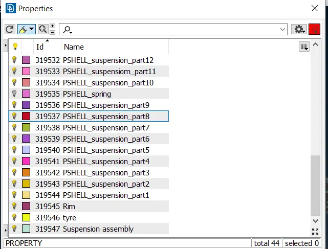
After asigning we have to identifie for which component we are going to which type of mesh or for the mid surface extraction.
So basically 2 type of component is here,one is or mid surface extractionn and shell mesh and second is for tria mesh and then sold meshing directly.
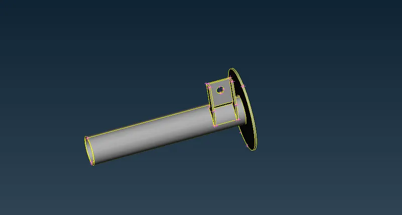
For these two parts only we are going for the mid surface process and hen meshing so for saving time i directly go for the casting one by one and there we have to give the target element length here is 4 and thickness of the component after that i m got the FE directly so i am showing you the image of the FE of these two part .
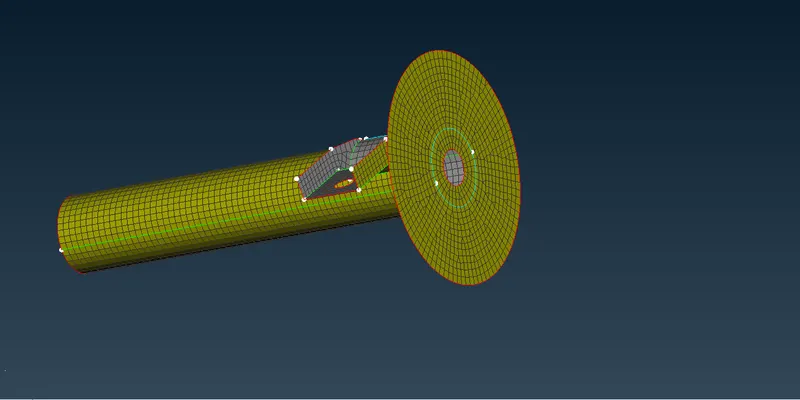
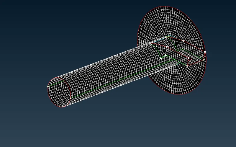
So here got the FE directly so all the mesh quality and the quality given in question is cleared.
Now i am showing for the solid meshing so for that we hace to mesh on the geometry part one by one.
so here we have 2 type of component in solid meshing 1 is for the uniform thickenss component and another is non uniform thickens.So for uniform thickness we have only 2 parts Tyre and Rim
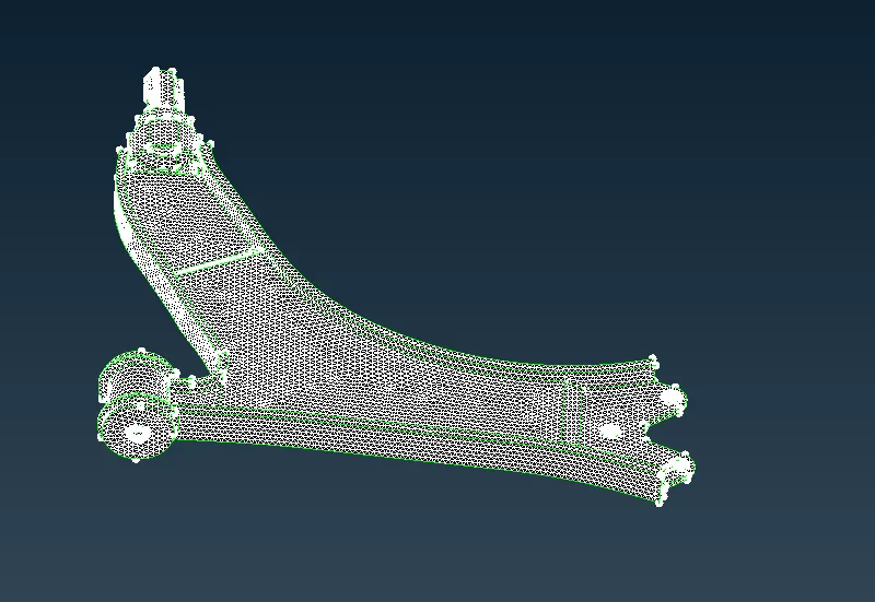
so i put the quality critaria as given in the question for he uniform thickness and meshed using ortho trias in the curve reason and on the plainer reasons i meshed with the tria as per the target element lengeth is here 6.5
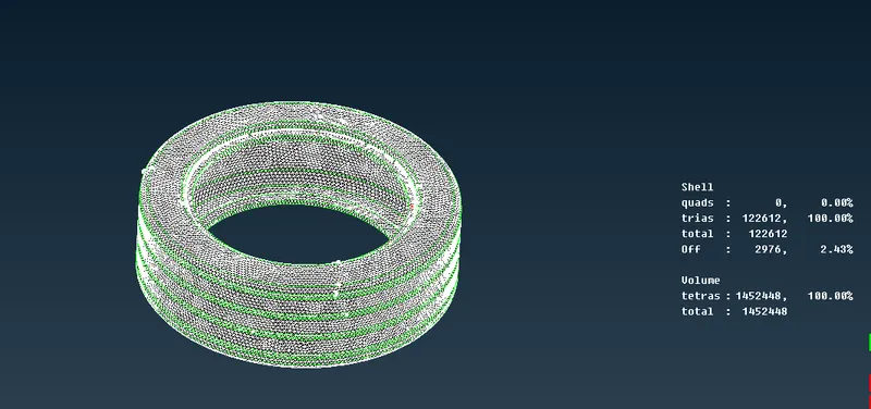
Here i meshed it but we have some quality issue i tried my best to reduse it by improve option and smooth option byt still having so quality of min/ max.
the same way we go for the rim also.And in the same way i changed the quality for the ununiform thicken parts as mensioned above in the question and meshed with orthp tria and tria mesh.
here is some picture of it .
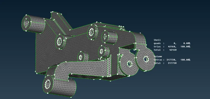
Now after this mesh we have to go for the solid meshing so before that we have to define the volume and pid for volume mesh.
so we have the option define and i go for manual and then after defining we have to go for the tetra mesh and here i used tetra rapid/tetra FEM.
so for the volume mesh we have only a quality critaria of tet collaps
Tetra Collapse:
Tet Collapse is the most important Quality criteria which is always checked while Tetra mesh is Performed (Tet Collapse is applicable to Tetra Elements only). As we know that Tetra element is a four noded element which has four sides and four nodes. The height of the Tetra element (h) is measured from each of the four nodes to its opposite face, and then divided by the Square root of the opposite face’s area (A). The minimum of four resulting values is then normalized by dividing it by 1.24.
As the Tetra collapses, the value approaches to 0.00. While a perfect Tetra element will have a value of 1.00. So, If the height of the tetra element is less than the desired height then that element will fail for Tet Collapse.
So after putting the quality i mesh the volume and now i am showing after the mesh and also i had cleared the quality by using fix quality option and also by smooth option.
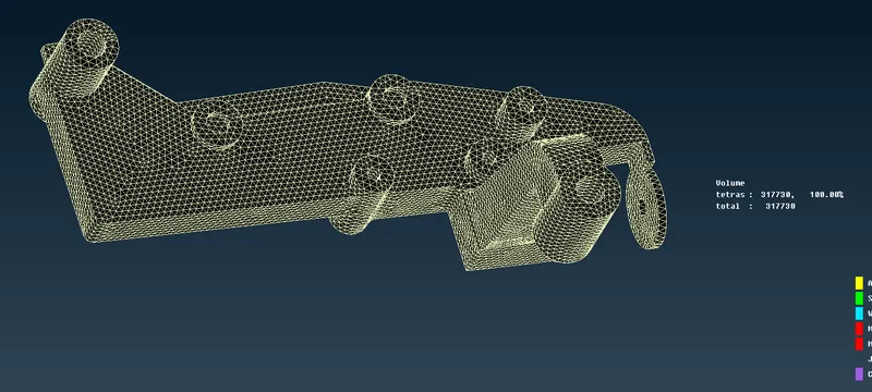
Like the same i went for all part,also we have to keep in mind that the PID for each solid components/parts must be different.
So after all the meshing of solid and shell i moving on to the Connection part.
So basically we have tomake here the rigid connection as here we are not capturing any mechanism so i used rigid bolt connection Seam weld connection and RBE3 CUSH RBE3 connection.
so for the rigid bolt conection we used the RBE2 many node option and two node option,here we have to make connection on the mesh which we have created on the geometry there we create the connection so that the solid is automatically connected to it.i am showing you some pictures of it.
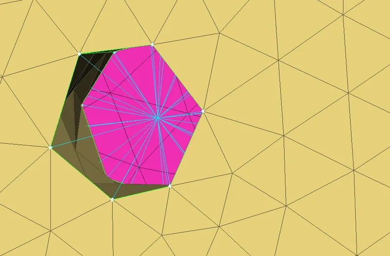
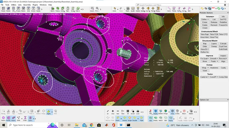
all these part is having rigid connection.
Second one is seam weld connection so we used the Feat2 curve option in perimetre of the mesh deck,by using that we create the curve where i want to do the seam weld as we don't have data for the connecton so i am asuming.
And then convert it to the seam line using the convert option, then after using connect option we use that seam line and creat the overlap shell joint.
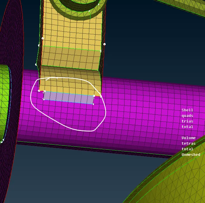
Here we have seam weld joint .
Last we use the CBUSH joint for connection of tire and RIM,as here is not mentioned for which joint i have to do so i just go with the CBUSH connection for that i created the cones to curve and then that curve is converted into spot line and then using connect option we go for RBE3 CBUSH RBE3 connection for the cnush joint.
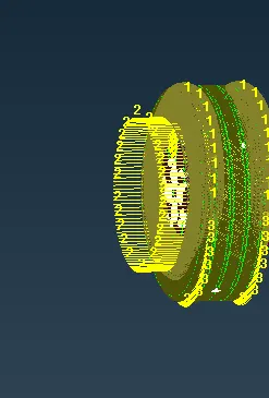
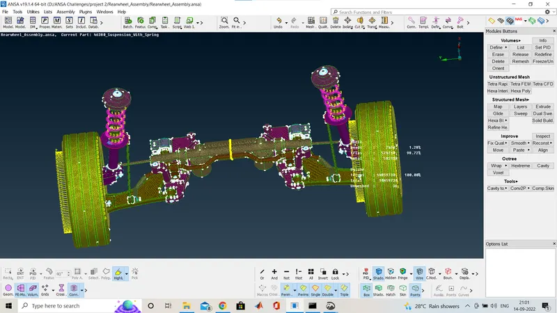
Now over all after the connection i do the symmetry option,so for that first i released the mesh, and then using transform option copy the entity and then do symmetry by using mirror 3 point plane .
The final image i have given below.
Learning Outcomes:
1) Meshing the given component using only tria and ortho tria elements.
2) Defining a volume and applying volume mesh or tetra mesh over selected volume and clearing errors such as kink, dip and collapse elements.
3) Making different type of connectiom
4) Doing symmetry of the component.
Conclusion:
We make the whole part by meshing using shell mesh and solid mess and after that we make all the connection.