Week 2 Railwheel and Track
Aim: Perform a static structural analysis on the Railwheel and Track setup under given load condition.
Objective:
Case 1: Multiply the bearing load by 5 times and compare the results with the load of 100000 N (As done in week 2 video). Compare the Total Deformation, Equivalent stress, and the life under both the loads
Case 2: Implement a User-defined result and calculate the Total Deformation from this result and check if it is the same as that obtained by the inbuilt result by ANSYS for a load of 100000 N.
Procedure:
Case 1: bearing load of 100000 N
Start the ANSYS Workbench and double click on static structural and rename it Railwheel_track.
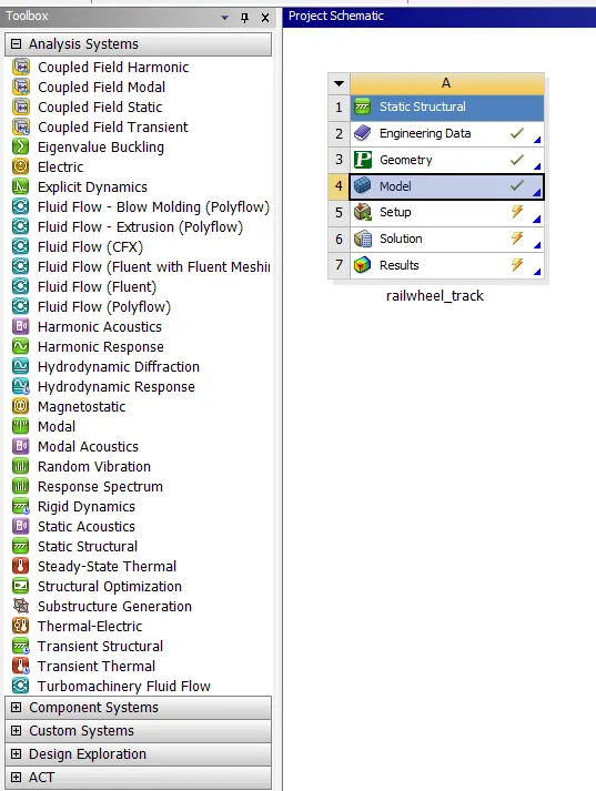
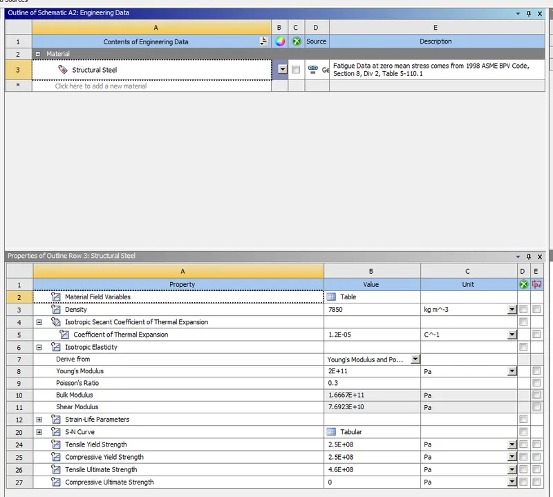
Now double click on engineering data which is here structural steel as default no need to change it.
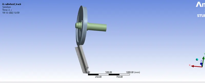
After that right click on the geometry and import the geometry available in the question. And here no changes required.
After that we have to right click on the model and click on update. After that double click on the model to edit in mechanical.
Now here first we have to assign contacts, and right click on contact and click on rename based on definition and again right click and click on flip contact to the target.
Then right click on the first contact frictional-wheel to rail and change the definition type to frictional and give friction coefficient 0.3 rest all as default.
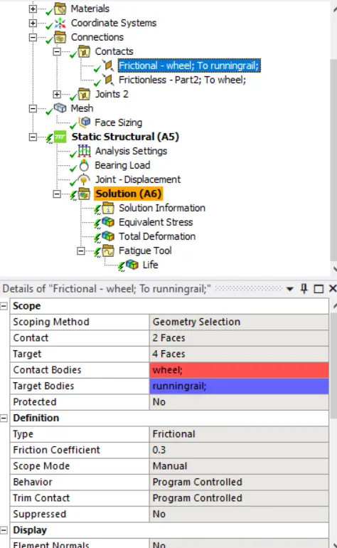
Second contact is wheel to shaft.
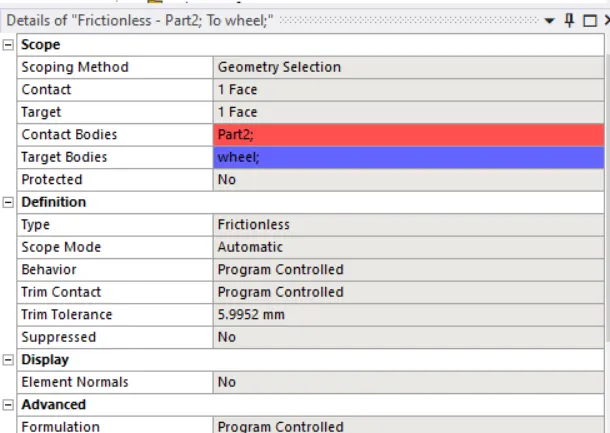
Only here i changed is definition type as frictonless.
And 3 joints one is fixed joind which is applied to both side of rail,second is translational joint which is applied to the shaft and the last one is planer joint which is applied to the plane side of the wheel.
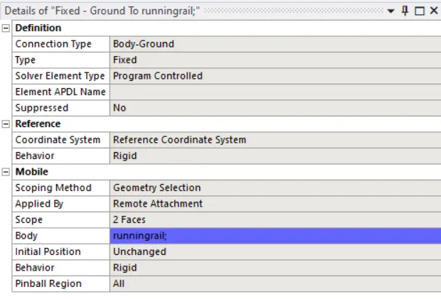
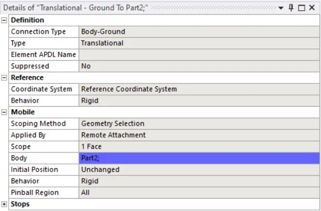
after the contacts we need to deside the mesh size here we have taken 35mm to entile and also we insert a face sizing of element size 35.
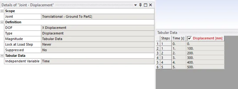
After that we have to give the boundry condition so here we have to give a translational motion of 500mm so here we insert a joint displacement load in a tabular data of each 100mm.
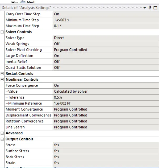
for the analysis setting.we have given 5 step and auto time steping on,defined by time,carry over time step on minimum time step 1E-03s max time step is 0.1s, solver type as direct and large deflection on,then in the output control all the parametre should be yes and in non liners control force convergence should be on.
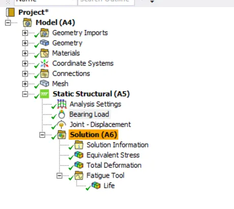
And a bearing load is applied of 100000N to the centro of the wheel in -y direction
finally the calculations for the equivalent stress,total deformation and the fatigue life cycle.
And then right click on solution and click on solve.
Results:
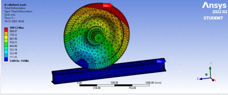
Total deformation:
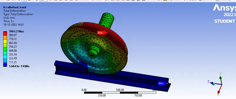
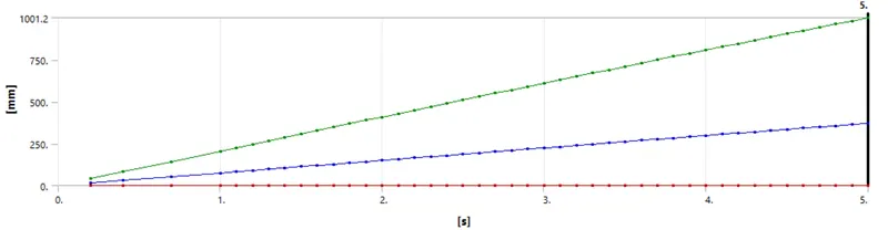
Here the maximum deformation is 1001.2 mm
Equivalent stress:
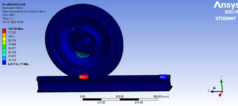
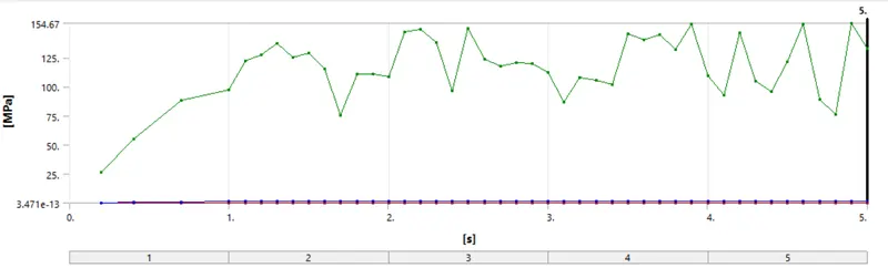
Here the maximum von mises stress is 132.56 MPa
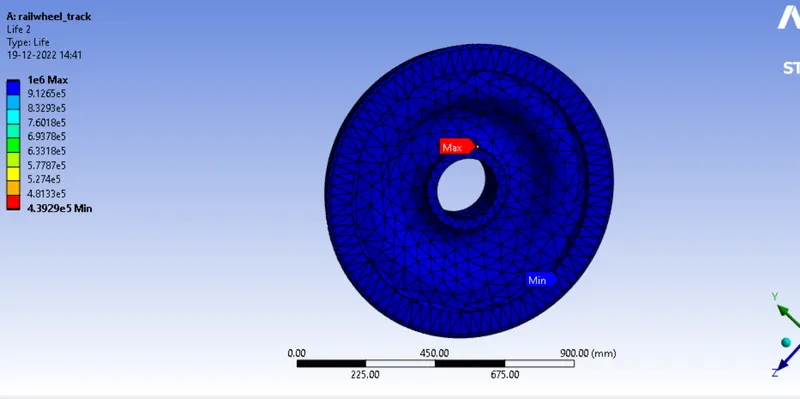
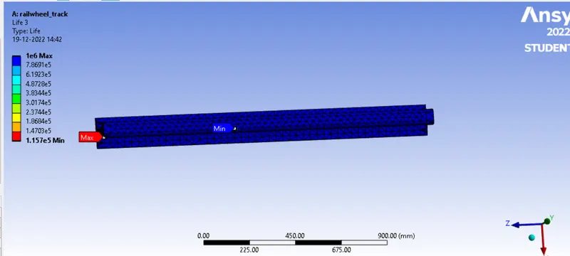
Life cycle:
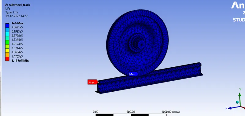
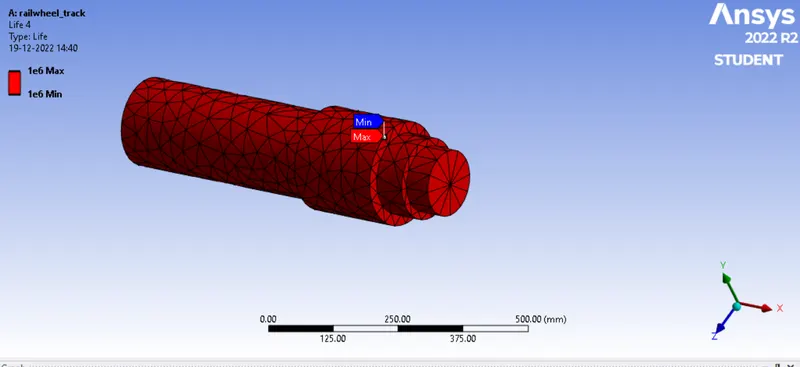
life of shaft
life of wheel
life of track
life cycle is same for all the three parts.
Now in the same case we have to just change the bearing load to 5times of the input load so it is about 500000N and rest all the thing is same here so lets see the results what all things change.
Equivalent stress:
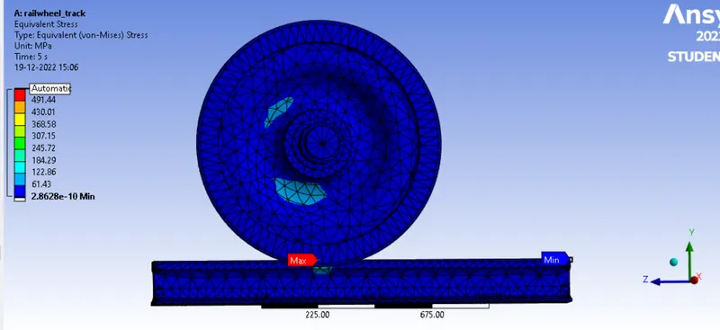
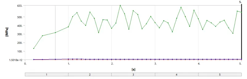
Here the max equivalent stress developed is 552.87 Mpa
Total deformation:
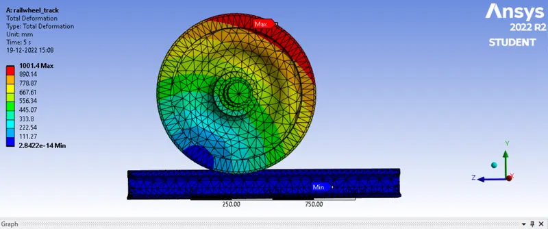
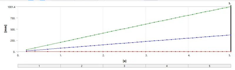
max Total deformation is 1001.4mm
Life Cycle:
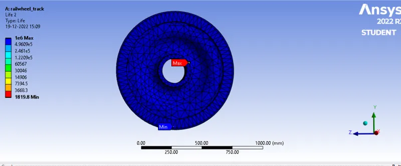
life cycle of wheel
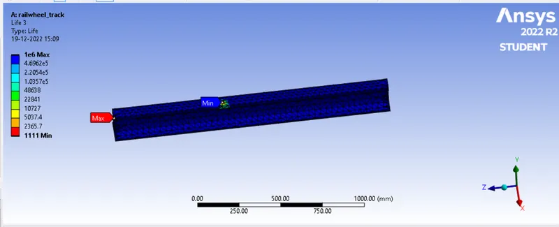
life cycle of track
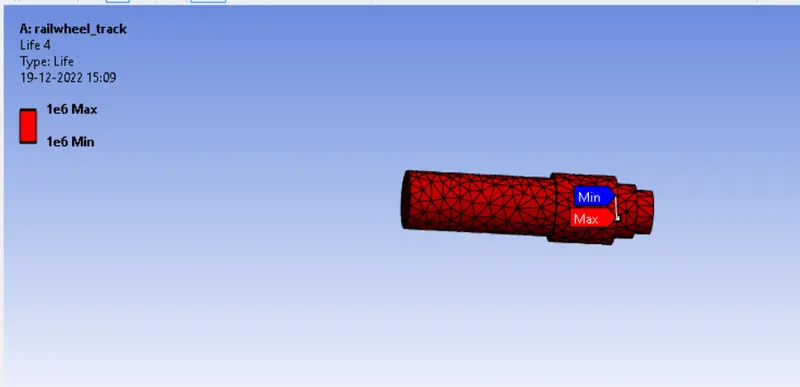
life cycle of shaft
| Bearing load (N) | Max Equivalent stress(Mpa) | Max Total deformation (mm) | life cycle |
| 100000 | 132.56 | 1001.2 | 1E+06 cycles |
| 500000 | 552.87 | 1001.4 | 1111. cycles |
Discussion:
Here we can see that by changing the load from 100000 N to 500000 N he stress value increases from 132.56 mpa to 552.87 mpa which a huge difference.
If we talk about the total deformation there is not much changes in deformation its increased by just 0.2 mm which is not much changes.
And the overall lyfe cycle at the bearing load of 100000N its 1E+06 cycle and at 500000N it is decreases to 1111 cycles.
Case 2: Implement a User-defined result and calculate the Total Deformation from this result and check if it is the same as that obtained by the inbuilt result by ANSYS for a load of 100000 N.
Procedure:
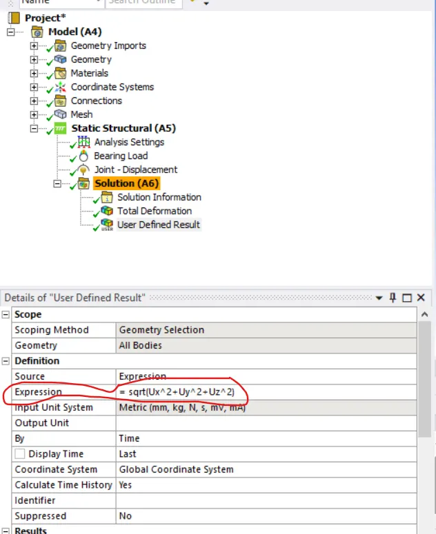
process for this case is same as case 1 just we have to add one more result in the solution part i.e, user defined and manually we have to put the formula for total deformation.
To find Total Deformation under User defined rsult, we have inputed an expression sqrt(Ux^2+Uy^2+Uz^2)
The results are shown below:
Total deformation at 100000N bearing load is
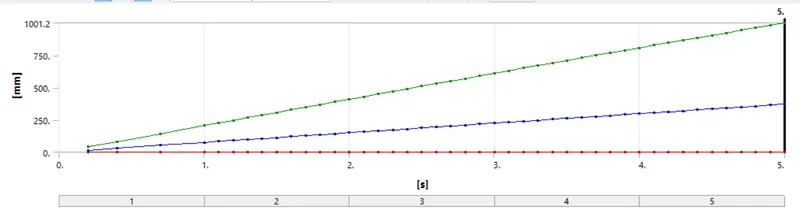
And the user defined total deformation results:
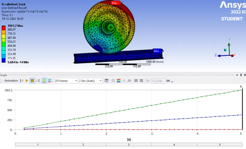
Now in this case we can see that the default max total deformation is 1001.2mm and the user defined total deformation is also 1001.2mm so both are giving same result.
CONCLUSION:
From the table we can say that the stress is Maximum at 500000N Load that is 552.87 and Minimum at 100000N Load that is 132.56. The Fatigue will be max at higher load of 500000N which is 1111 cycles And the Maximum fatigue at 100000 N load is 1E+06cycles. As well as the Total Deformation also remains same for both the cases.
The user defined result for Total Deformation and the Inbuild result for Total Deformation are same.