Frontal crash BIW
OBJECTIVE
To apply the given condition and plot the energy errors
PROCEDURE
- Check unit system and either follow[Mg mm s] or [Kg mm ms]:
The given model is recommended with a Kg mm ms unit system, if not change it through notepad without a change in spacing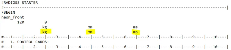
- Create an appropriate interface, friction 0.2, and recommended parameters:
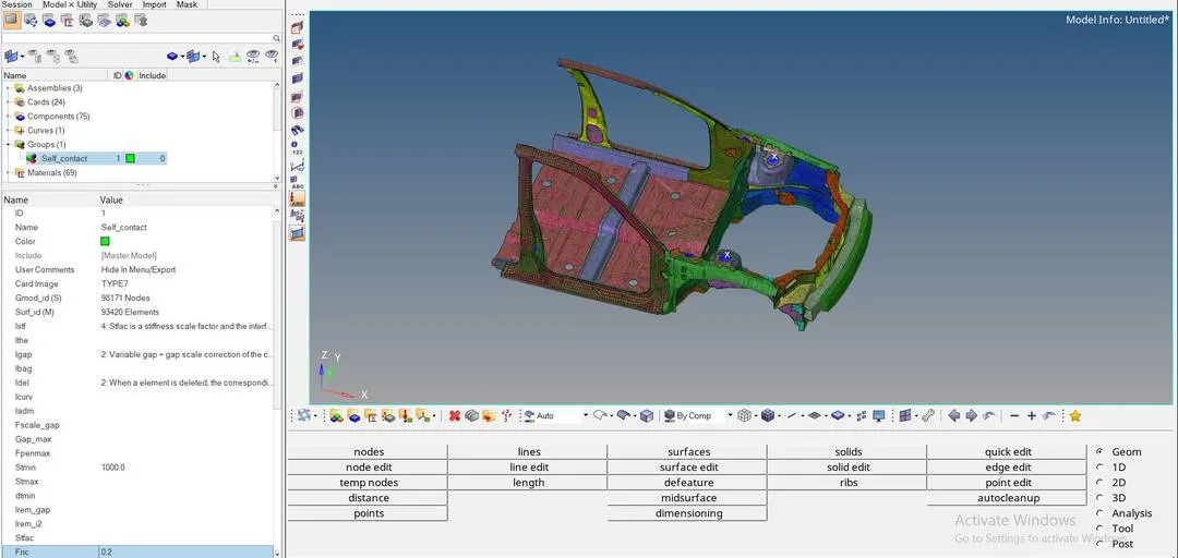
To create an appropriate interface, delete the existing group from the given model
Hide the rigid body to select the slave nodes & master segment from menu bar view > browsers > hypermesh > mask - remove the rigid body
Create self contact by model > create > contact, select the card image as type7, friction value as 0.2 and apply the following recommended properties - Make sure of no penetrations and intersection:
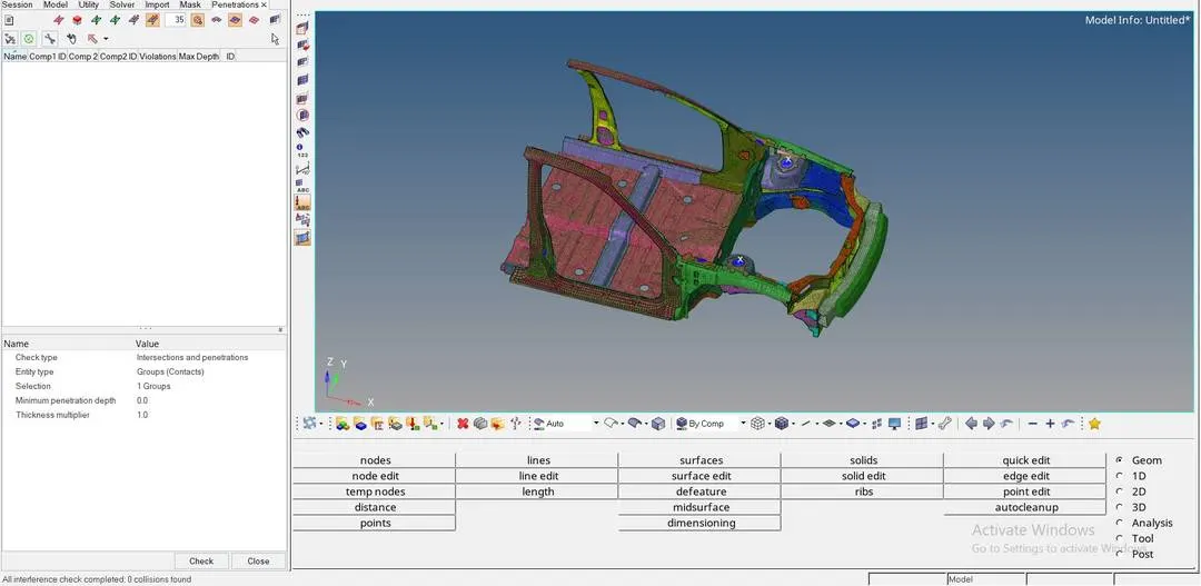
For penetration check from the menu bar tools > penetration check > select the group from the entity and hit
0 collisions found would be defined when there is no penetration - Correct rigid bodies if any issues:
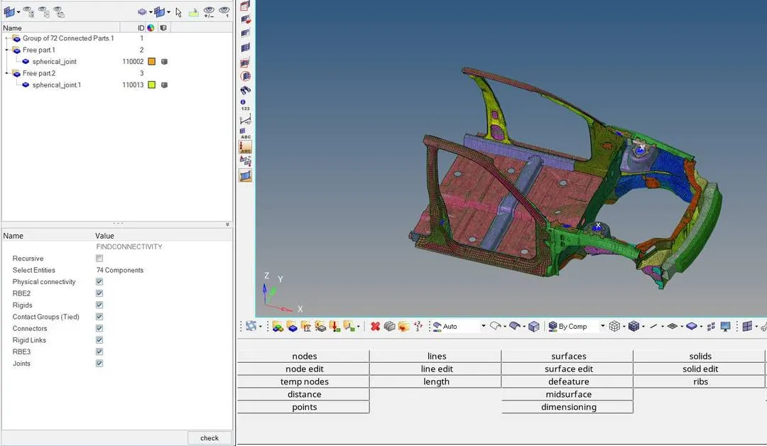
To check unwanted rigid bodies from the menu Tools > Find connectivity
Select the entities as components and check, Free part represent unwanted joint
Delete the unwanted joint from the components section and check for correction if it exists - Create a rigid wall with friction 0.1:
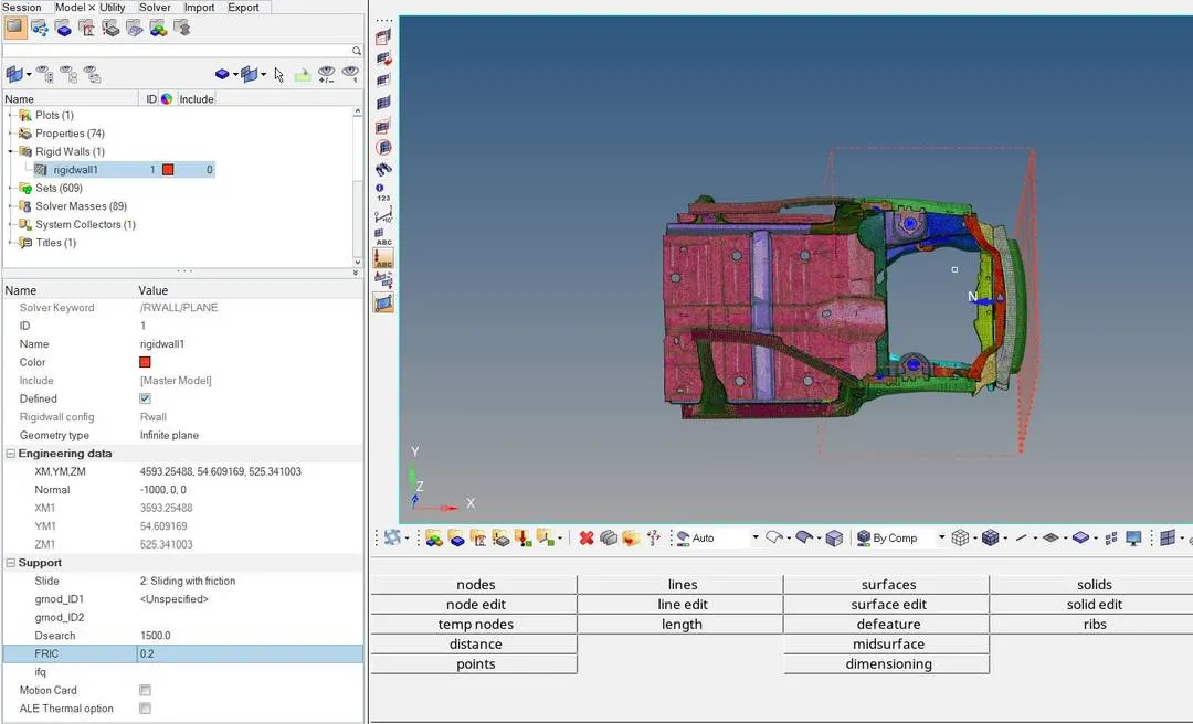
Creating a rigid wall from model > create > rigid wall, select the node and normal force from the entity browser
To apply friction value change the slide value as 2: Sliding with friction, FRIC - 0.2 - Compare the model weight with the full-scale 300k nodes model and use added masses to reach a target weight of 700kg while getting CG about the required range:
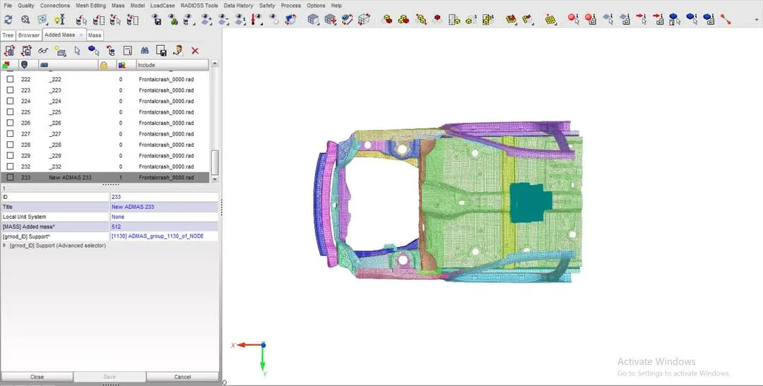
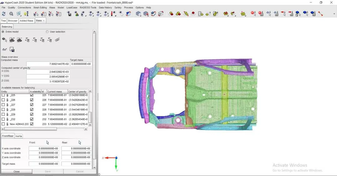
Export the model from hypermesh as solver deck, cause mass balancing could be easy at hypercrash
Check the COG virtually from the mass balancing and edit accordingly with an additional mass of succeeding 700kg
Create an entity as type=2 mass is distributed to each node of the node group, select the nodes and check the COG from mass balancing - Initial velocity 35 mph:
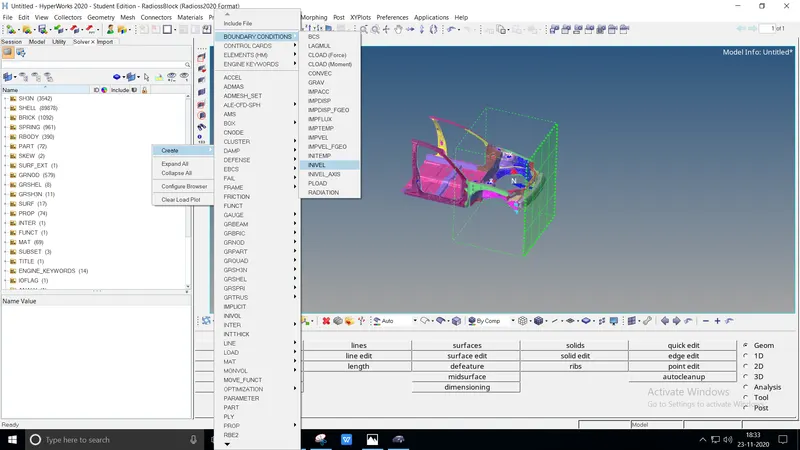
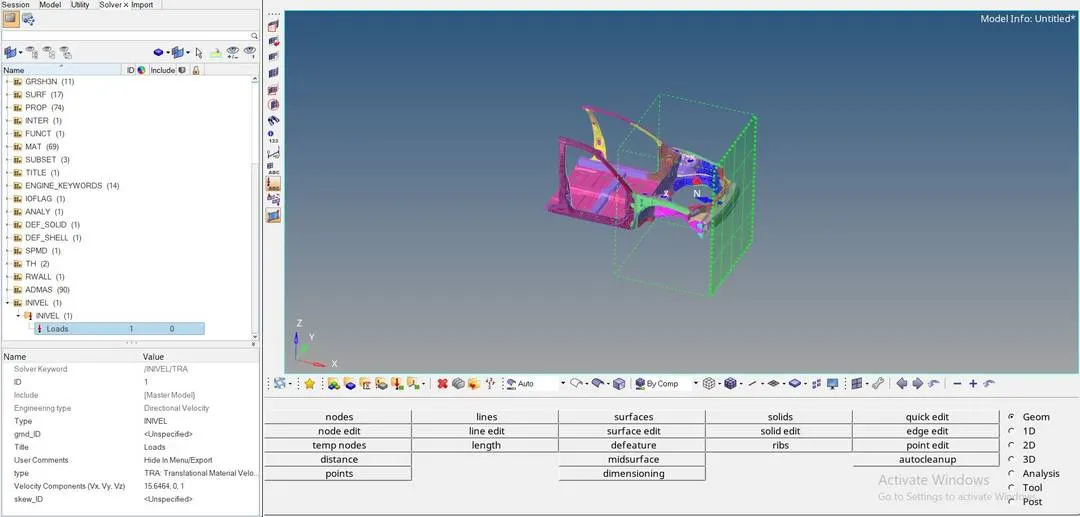
The given model has existed with units kg, mm, ms
Convert the given velocity mph>ms, we'll get 35mph > 15.6464
Open solver > create > boundary conditions > invel, create a grnd_ID by defining the nodes and enter the converting value at velocity components - Use model checker to ensure good quality:
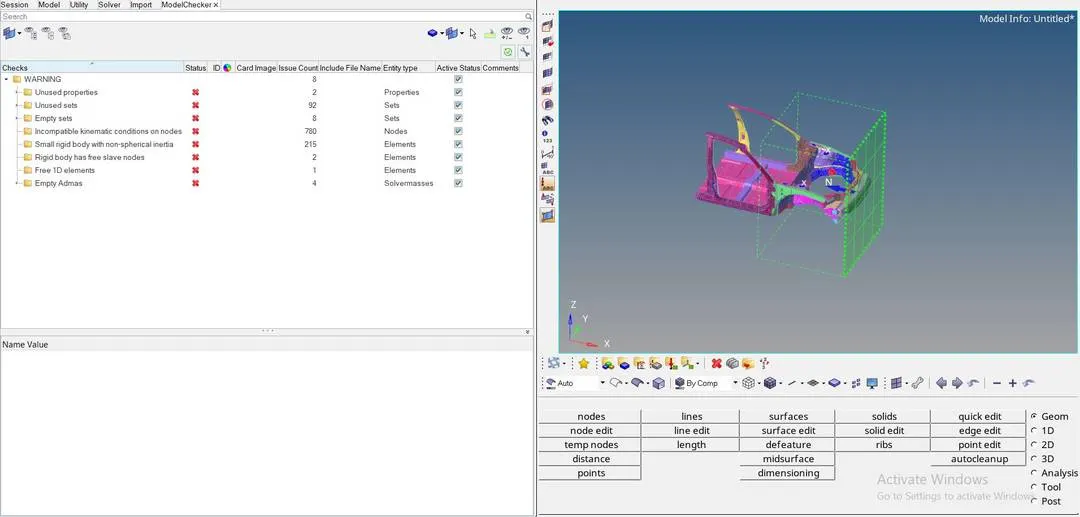
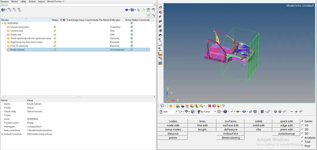
From the menu bar tools,> model checker > radioss block, the model checker browser will open to the left
Run the model checker, list of warnings with subfiles will be displayed on the browser
Delete the entire warning files and check until no warnings displays - Time-step- 0.5 to 0.1 microseconds:
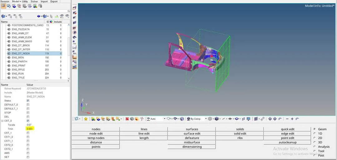
The given model has existed with units kg, mm, ms
Convert the given value microseconds > milliseconds, we'll get 0.3 > 0.003
Open model > cards > ENG_DT_NODA > change the Tmin value as converted value i.e., 0.003 - Sectional force in the rails at a location of indicated node 174247:
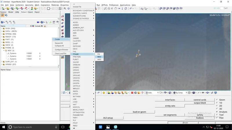
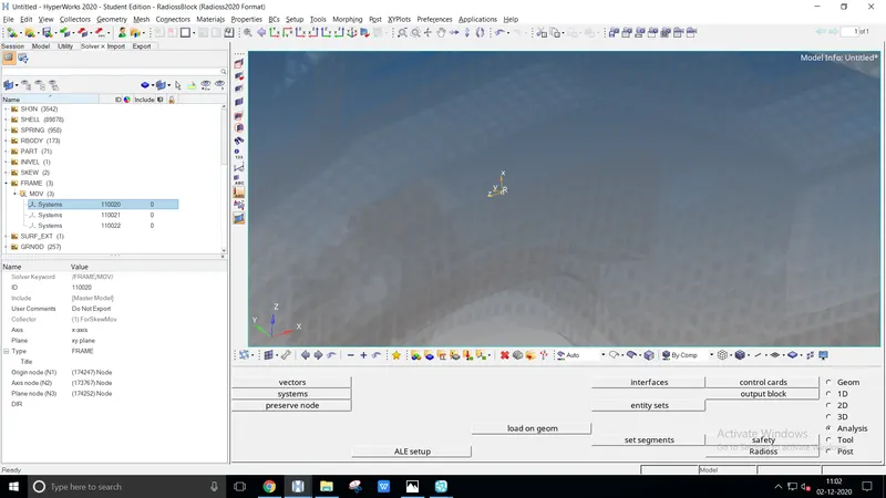
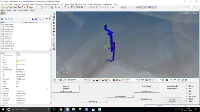
To create a sectional plane solver > create > frame > MOV an entity browser open
Select the node N1, N2, N3 axis accordingly. The local axis frame created perpendicularly to Z-axis
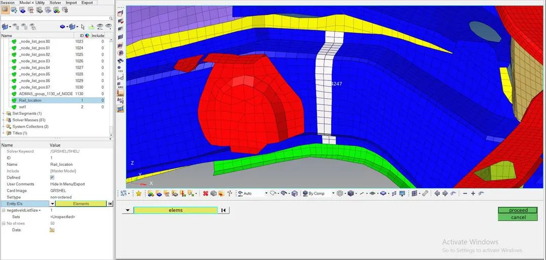
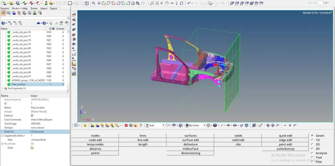
Create a set of elements representing the local frame entirely vertical, Open model > create > set, select the element's ID
Again solver > sect > sect, select the existing nodes, frame_ID, and grshell_id where we're using. Create a time history step as solver > th > sect and select the entity_ID - The axial force received on the rails from bumper:
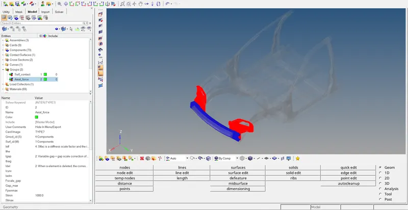
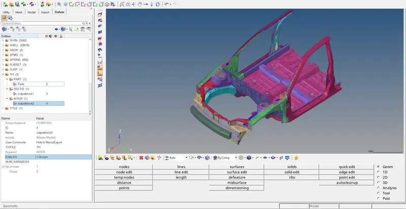 |
|
For creating axial force we need to create a contact, model > create > contact - select type 7
Provide recommended parameters and select the components at entity_ID. Create a time history step solver > th > inter from entity_ID select the group - Shotgun cross-sectional forces:
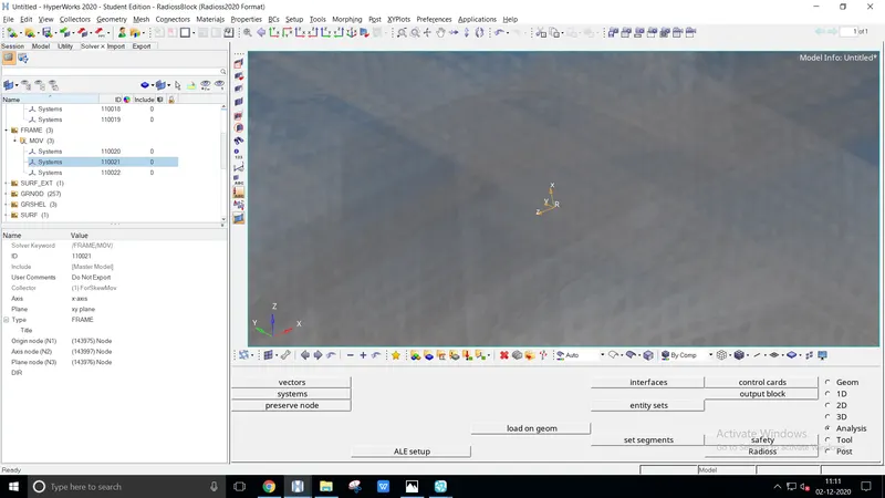
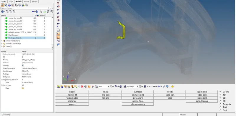
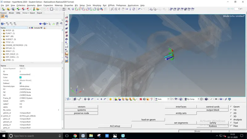
The shotgun placed behind the bumper of the car, a sectional force is done before at the indicated node
Do the same procedure as we've used before - A-pillar cross-section:
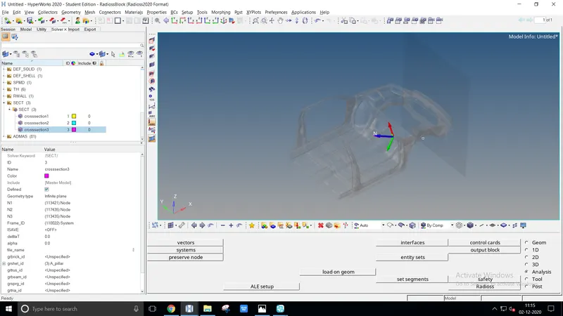
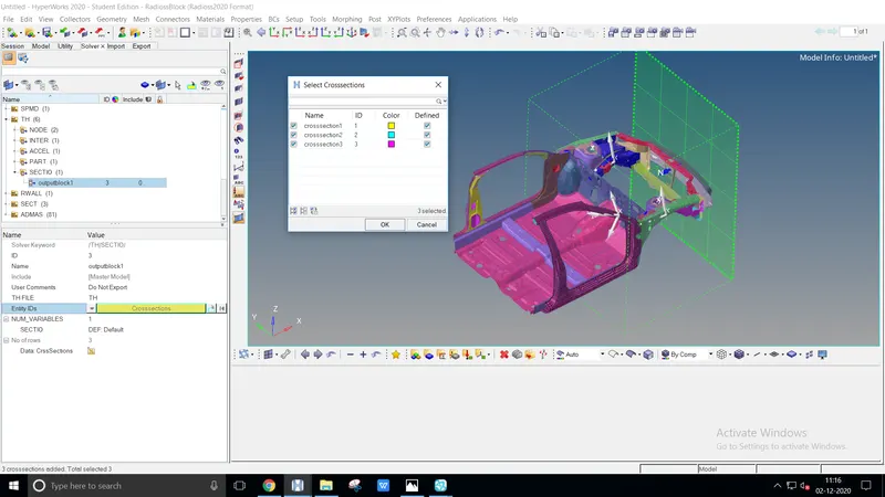
A pillar is located on the front of the door, sectional force is applied as applied before
After creating the sectional plane create a time history step, create > th > sectio entity_ID- select the three sectional plane - Acceleration curve received on the accelerometer at base of B pillar rocker:
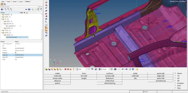
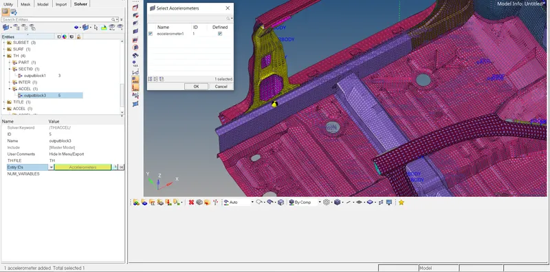
To create accelerometer, model > create > accelerometer point a node at the base of b pillar
Also, create a time step for the accelerometer solver > the > accel select the entity_ID - Intrusions on the dash wall 66695,66244:
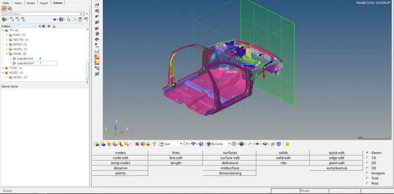
Create a node at the dash wall from solver create > th > node select the node_id with the given ID
INFERENCE
SIMULATION VALUE AND GRAPH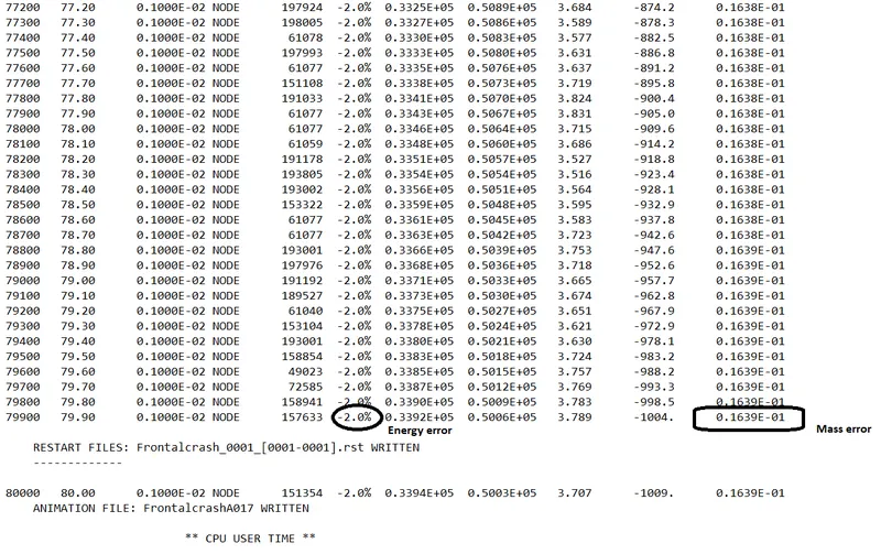
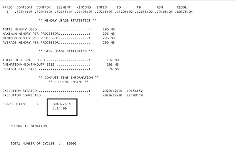
Check the simulation process by ensuring the data cards, given condition and save it at the properly defined folder
The error should be below -5.0% to get better results under the process. The determining values are energy error -2.0%, mass error 0.1639E-01
HYPERGRAPH 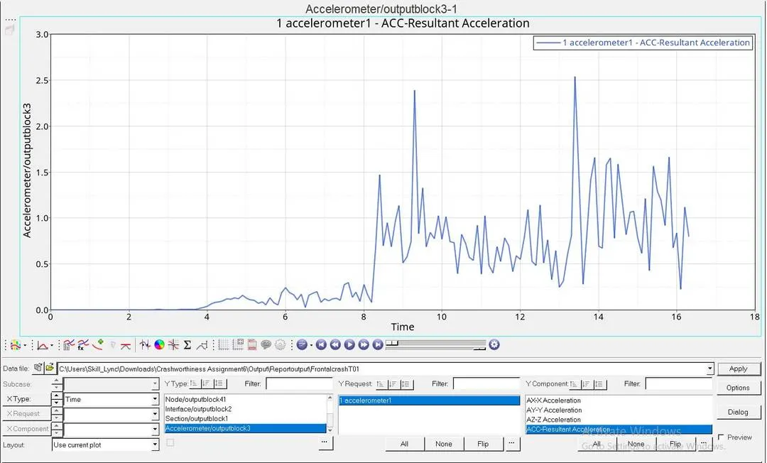
The accelerometer denotes an abrupt graph of forces acting among the direction towards
The result of Accelerometer exceeds up to 2.6th of the value
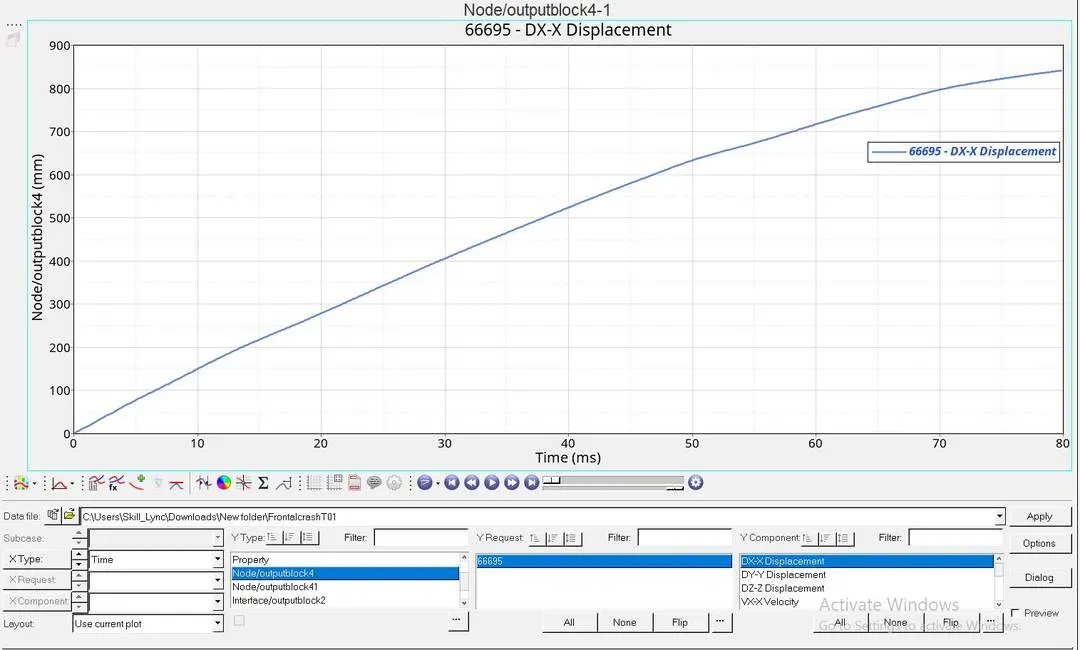
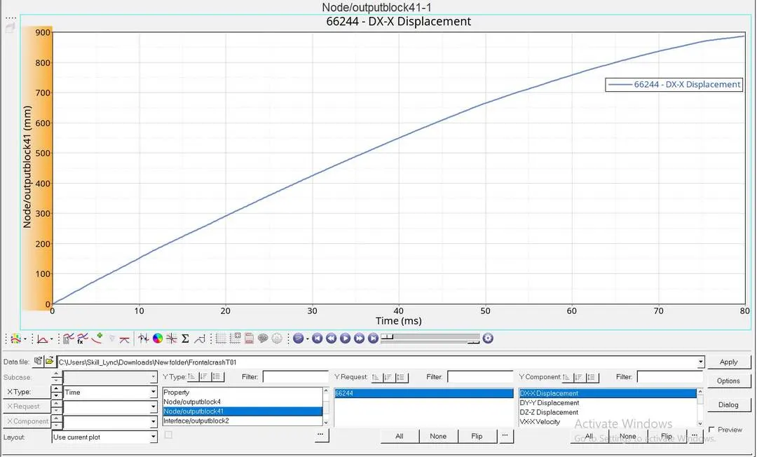
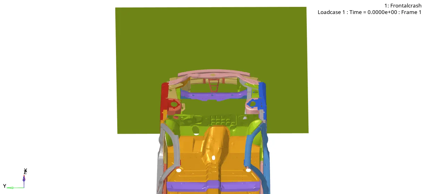
The nodal values implemented some amount of forces exhibit from the wall, both the node performs the same amount of value
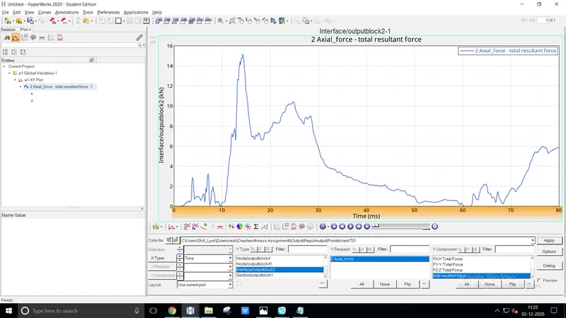
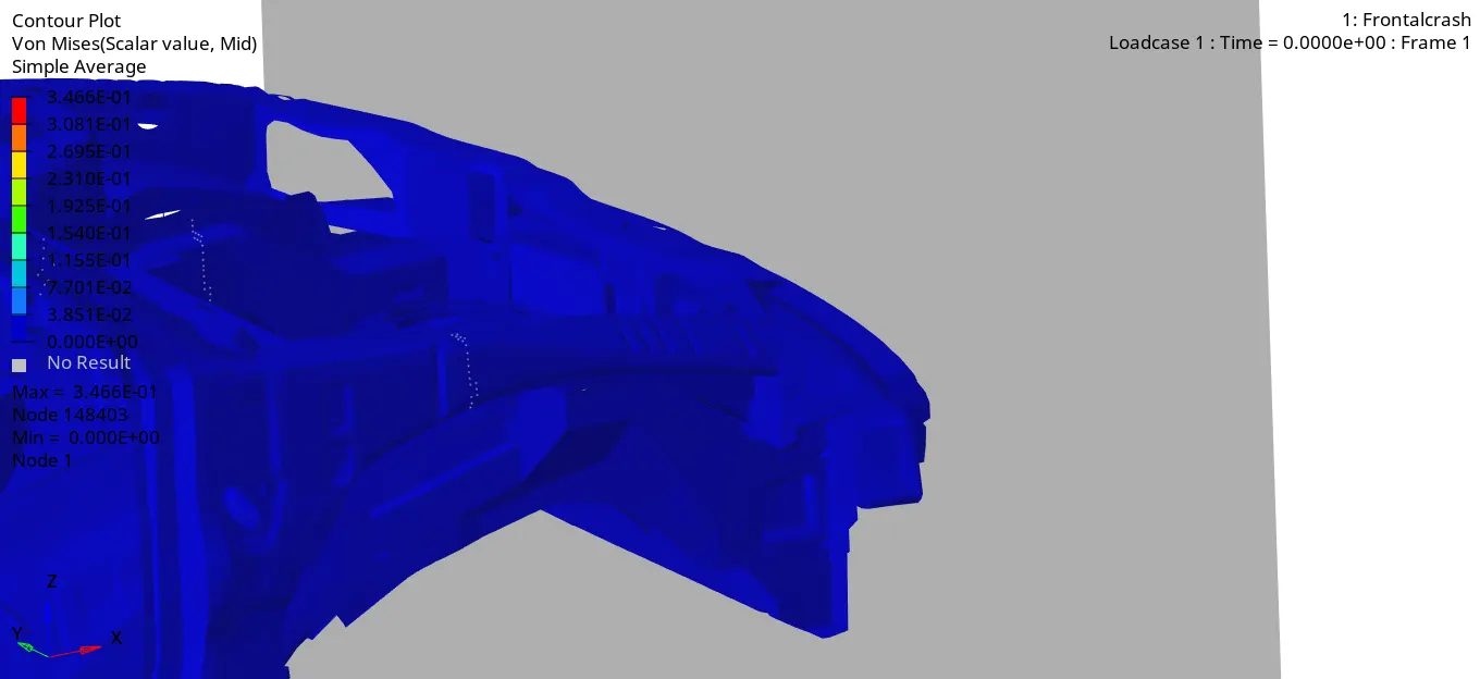
The above gif file portrays the axial forces acting on the bumper
The sudden increase and decrease of graphical value determines forces expands through the body
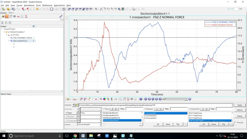
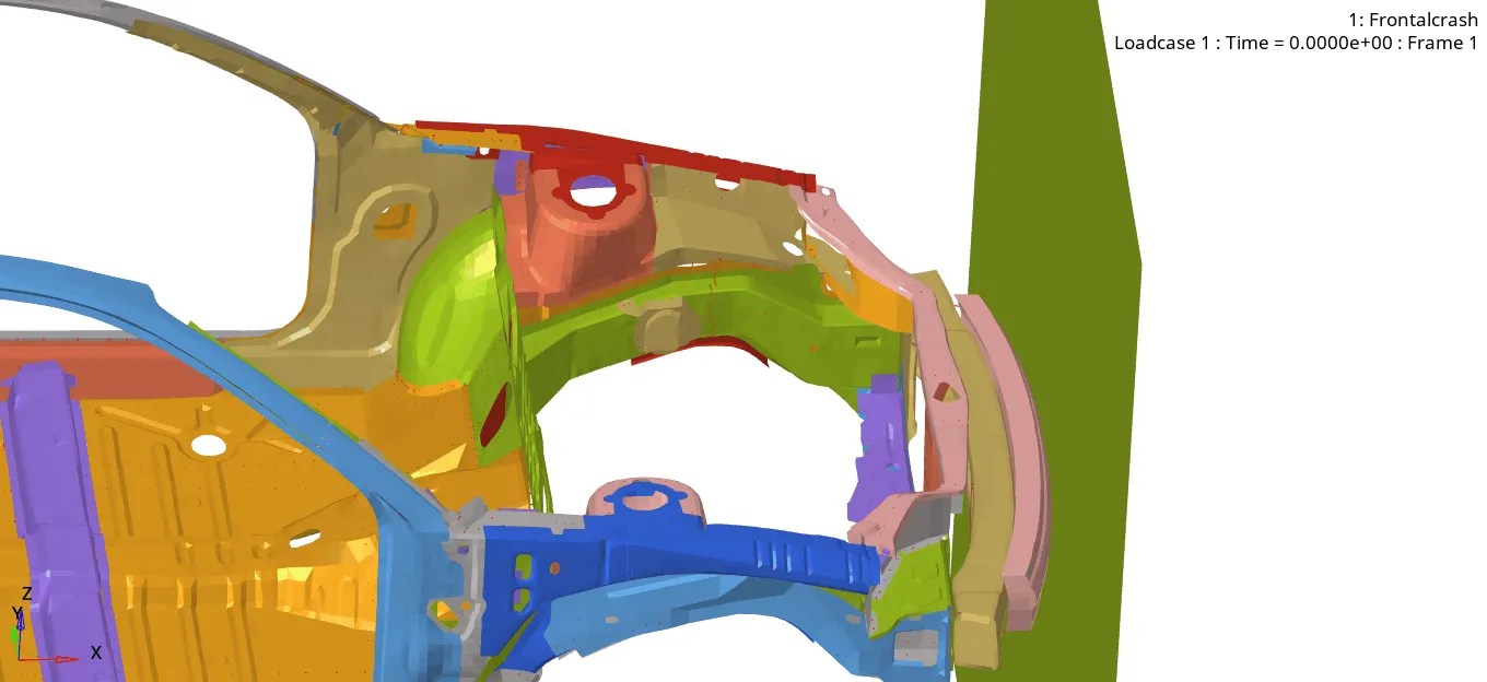
The sectional force behind the shotgun position provides an amount of normal force of 0.3KN at max
It implies a resultant force hit the opposite value because of global direction
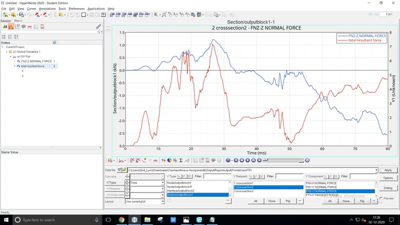
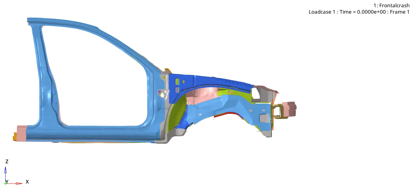
The sectional force at the shotgun hit directly without traversing from the other components
As the force act directly provides an amount up to 1.3KN
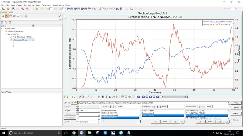
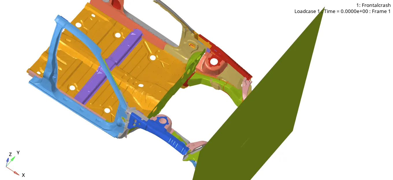
Here in this sectional area, the force transverse through primary components to the A-pillar
The normal force has an amount of value up to 0.275KN
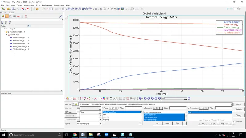
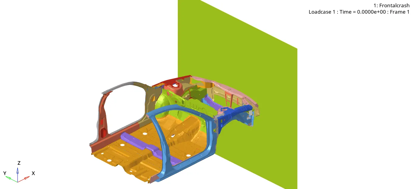
The global variables determine the internal energy is absorbed during the impact of the rigid wall
The kinetic energy gets dropped by virtue of a motion passes through the wall
The contact energy is less comparatively because of the low velocity
CONCLUSION
The errors are plotted according to each inquisition
From the above cases, the error value didn't exceed the critical range