Week-6 Calculate the Stretch Ratio by comparing the ELFORM (-2,-1,1,2) with Ogden_Material Model.
Aim:
To perform the simulation using ELFORM- 1,2,-1,-2 and calculate a stretch ratio
Objective:
- To Create a block of 10mmx10mmx10mm dimension with 10 elements for each direction and use the material card attached (Ogden_Material.k) with given properties
- Use appropriate boundary conditions to simulate tensile behavior for the model and finally compare the results from your simulation using engineering stress vs stretch ratio
- Use a proper solver (Implicit/Explicit)
Procedure:
Creating solid mesh
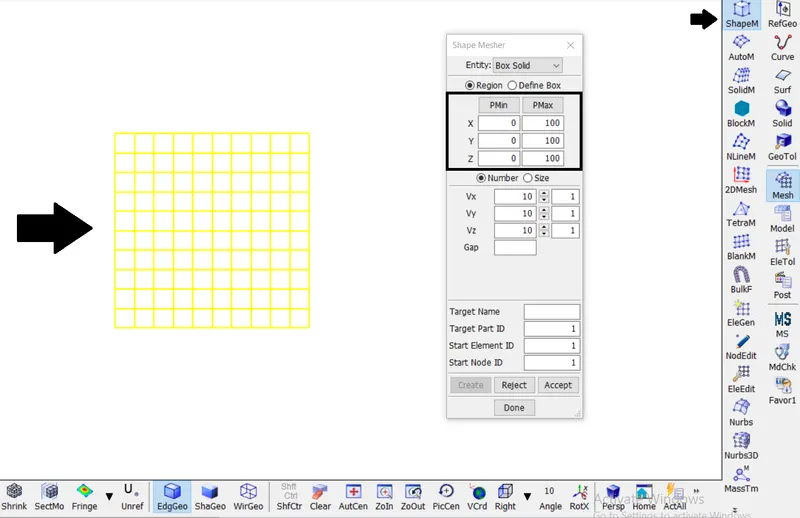
- The solid block of 10mmx10mmx10mm dimension with 10 elements for each direction is crested using Shape Mesher from Mesh option
Section
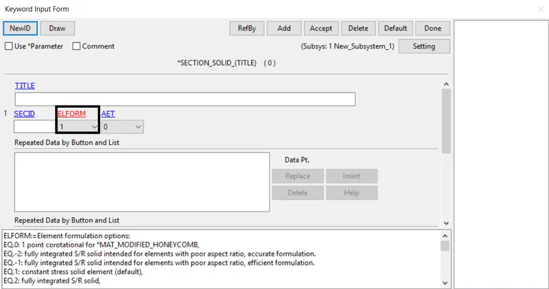
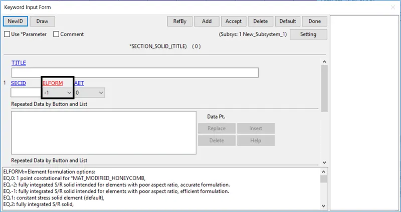
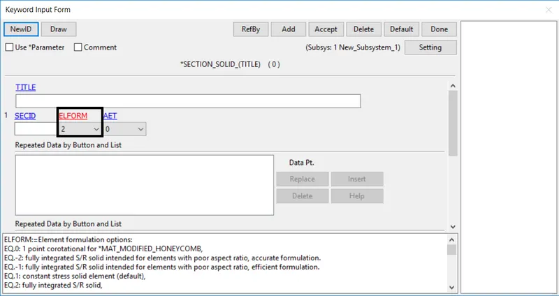
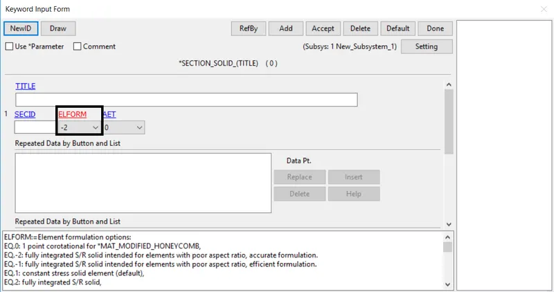
- The Solid_section is created by section option using a different type of ELFORM such as,
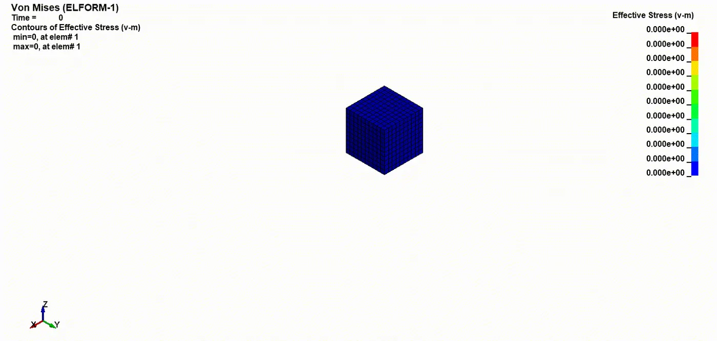
Case (1). ELFORM = 1, Constant stress solid element
Case (2). ELFORM = -1, Fully integrated S/R solid intended for elements with poor aspect ratio, efficient formulation
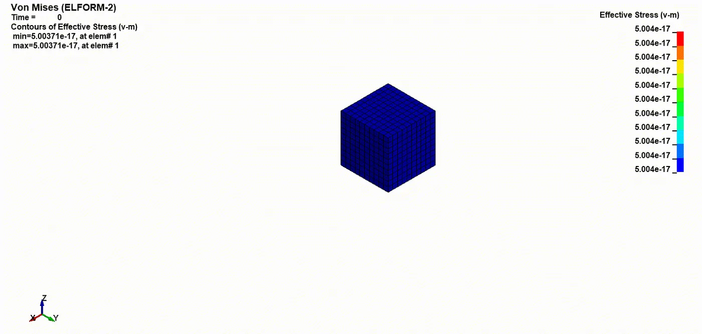
Case (3). ELFORM = 2, Fully integrated S/R solid
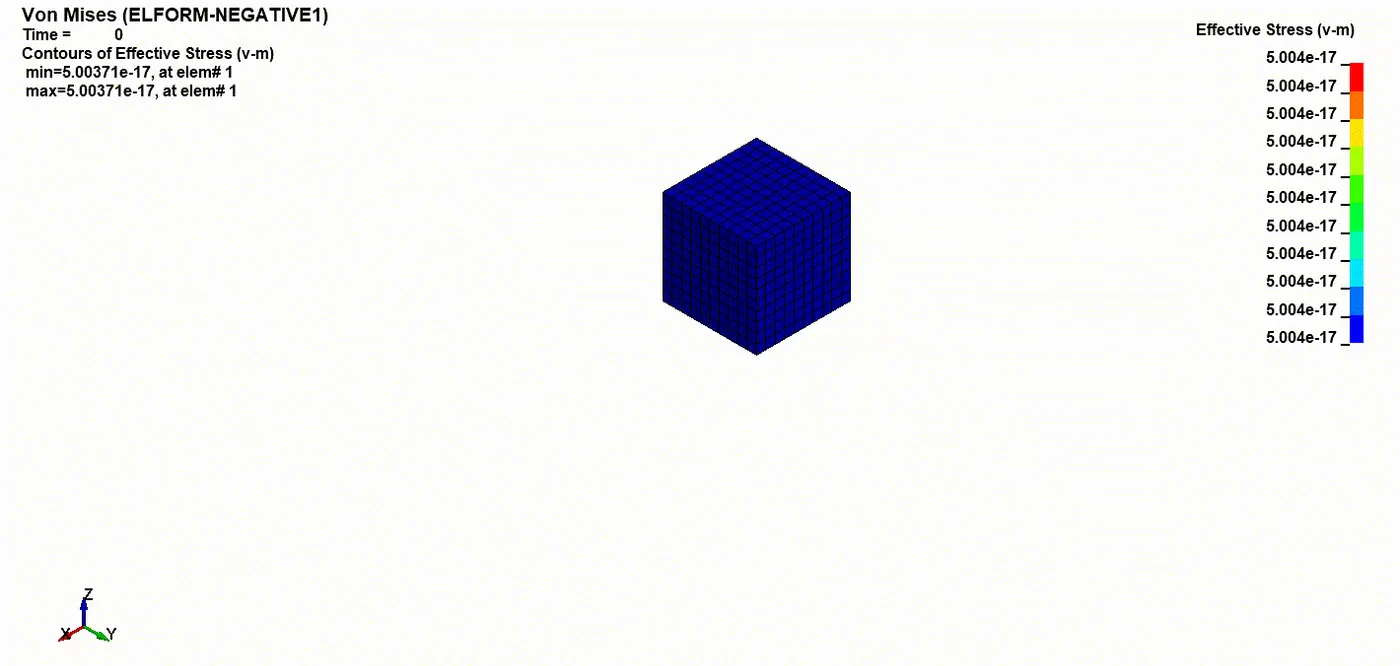
Case (4). ELFORM = -2, Fully integrated S/R solid intended for elements with poor aspect ratio, accurate formulation
Material
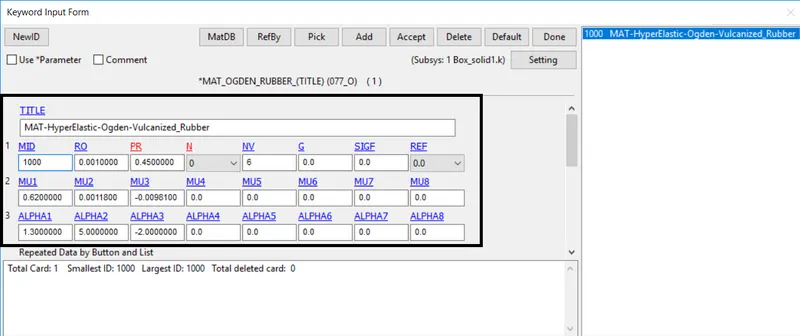
- The material card has been provided in the keyword file, the unit system followed is gm-mm-ms and it is assigned to the solid block part
Part
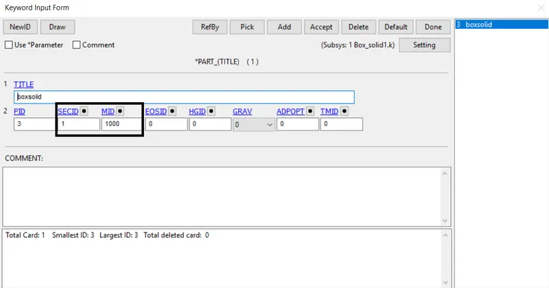
- The material and section properties are assigned to the solid part
Boundary condition
- To perform the uniaxial tensile test on the part, the faces of one of the nodes are constrained along the X-axis
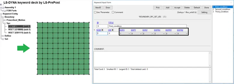
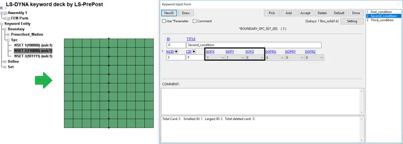
- Then creating the vertical middle nodes along Z- direction, to get Y- direction constrained
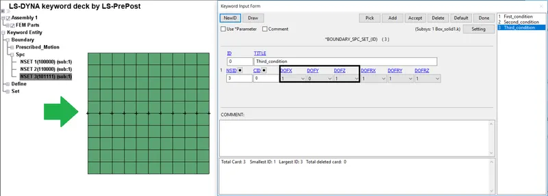
- Finally creating the horizontal middle nodes along Y- direction, to get Z-direction constrained
Prescribed motion
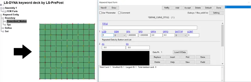
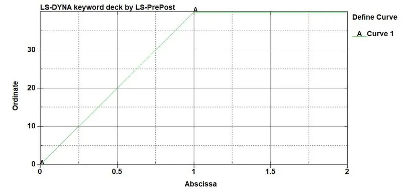
- The minimum displacement to be applied on the moving surface model to attain a stretch ratio of 5, is calculated by using the following relation,
λ=1+εe
Engineering Strain, εe=δL/L
λ=5,L=10
5=1+(δL/10)
δL=40mm - Hence, the minimum value of 40mm is taken to define the load curve
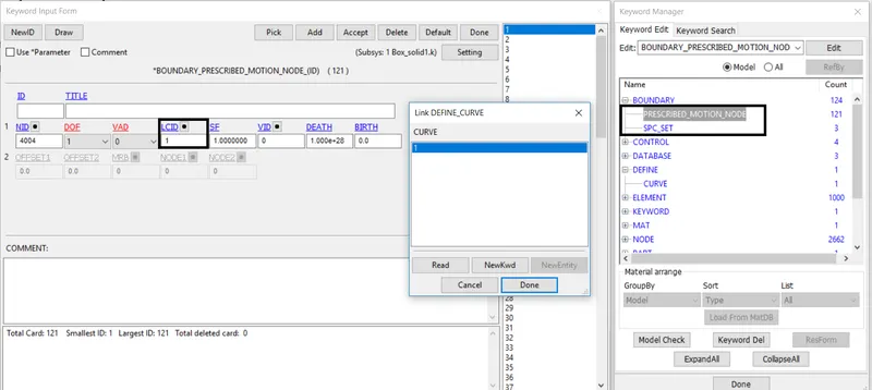
Generally in LS pre-post, the solver worked as an explicit method. To perform an Implicit solver the following keywords are needed to switch from implicit to explicit
Control Cards
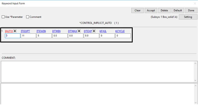
- CONTROL_IMPLICIT_AUTO is used for automatic time step control during implicit analysis. The input value for the automatic time step control flag, IAUTO= 1 is used to activate the implicit method
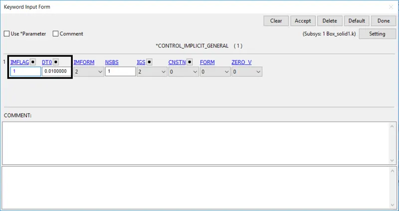
- CONTROL_IMPLICIT_GENERAL is used to activate implicit analysis and define associated control parameters
The input value for IMFLAG=Implicit/Explicit, switching flag = 1 (implicit analysis). DT0 refers to the Initial time step size for implicit analysis = 0.01
Database
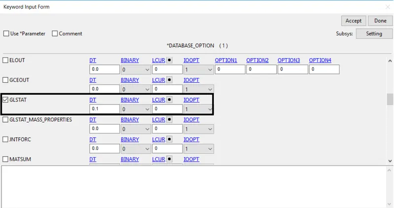
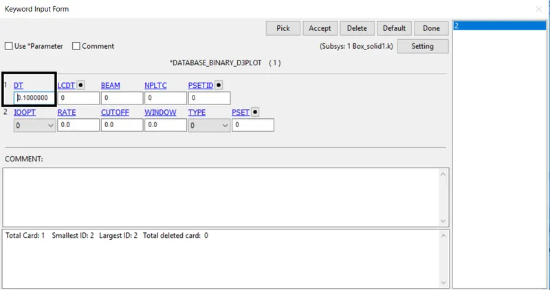
- The time step value of 0.01 ms is given for the BINARY_D3PLOT, DATABASE_ASCII for GLSAT
Results
Von Mises
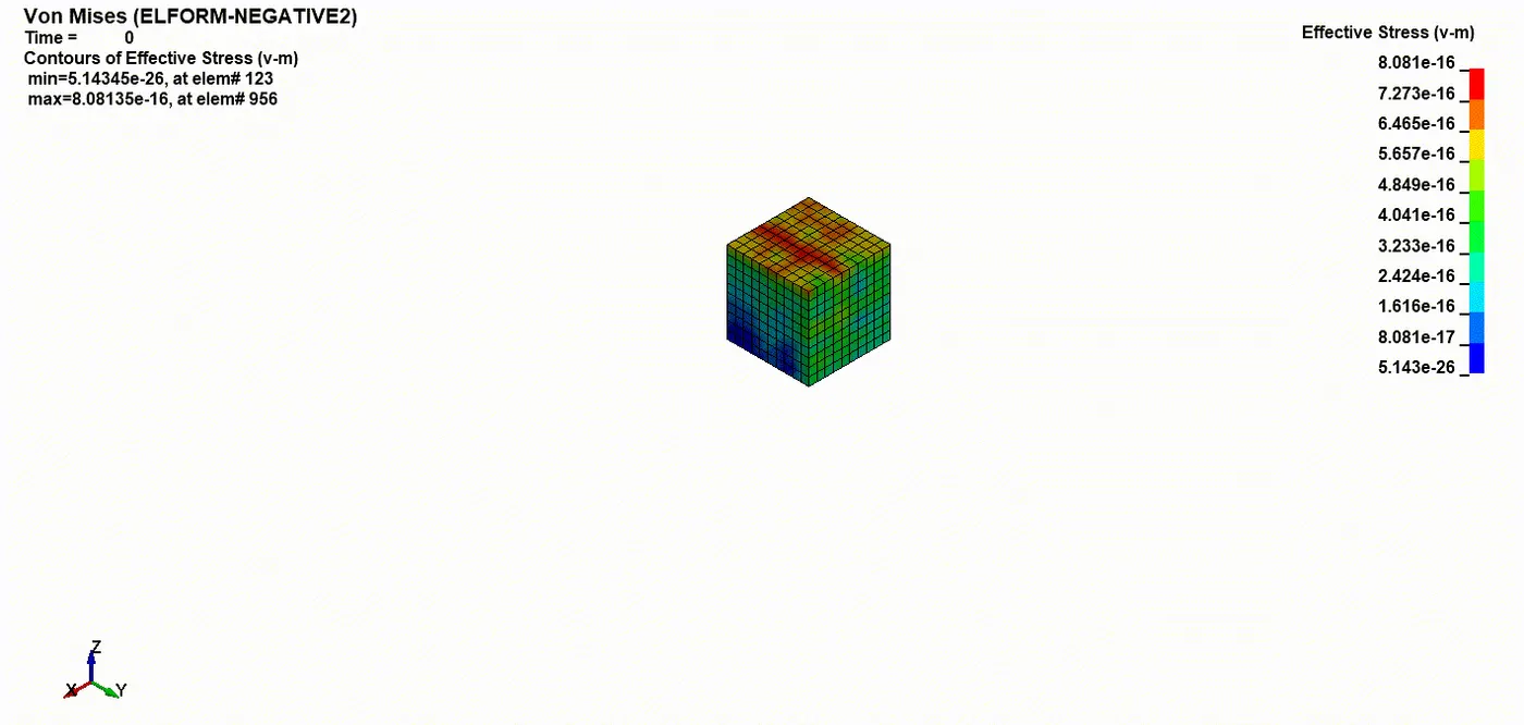
Calculation of Engineering stress/strain and stretch ratio
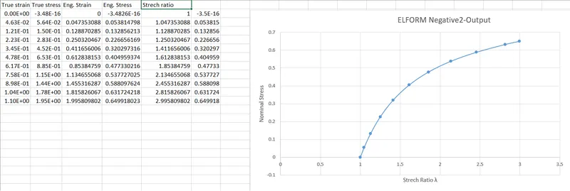
- In LS-DYNA always the output of stress and strains I get from the Post fringe comp Stress/Strain are given as true stress and strains
To find the engineering stress/strain and stretch ratio following relations are used,
I know that True stress, σt=σe(1+ϵe)
Engineering stress, σe=σt / (1+ϵe)
Similarly, True strain, ϵt=ln(1+ϵe)
Engineering strain, ϵe=eϵt−1
Stretch ratio, λ=1+εe - Using excel I calculated our Engineering Stress (ϵe) and Stretch Ratio (λ) using the above relations
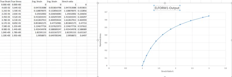
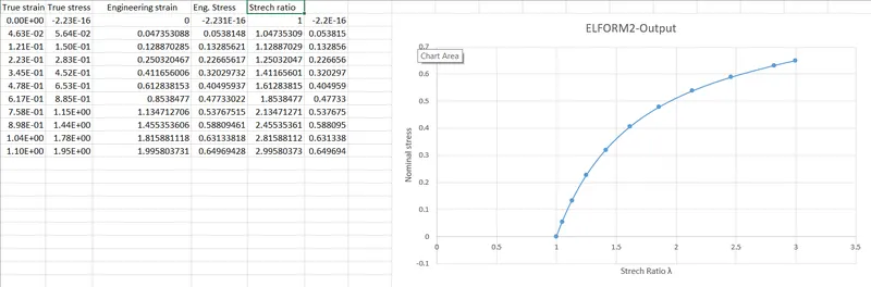
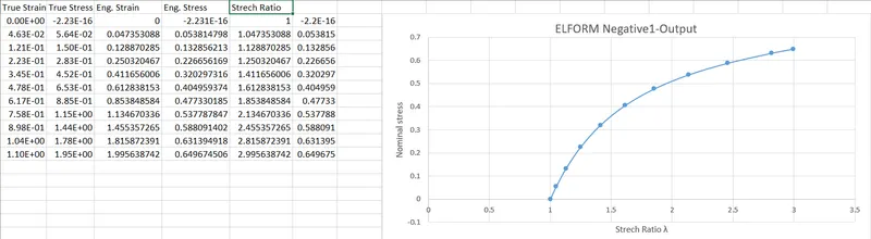
Conclusion:
- A FE model was understood and created a solid block with Ogden material to simulate a uniaxial tension test for different cases of ELFORM (1, -1, 2, -2)
- The Engineering stress/strain and stretch ratio was calculated to plot a graph of Eng. stress vs stretch ratio up to stretch ratio 5
- The uniaxial tension test was solved using an implicit solver since the analysis is similar to a quasi-static analysis on a hyperelastic non-linear material with slow steady loading conditions