3D Meshing and Engine simulation
Aim
- To calculate Speed, Time, and TFreq on the given engine file
- To perform 3D meshing
Check the material properties of the rail component and calculate the speed of sound in steel rail
`Delta t` = L/C => L/ `sqrt (E/ rho)`
`E`= 210000 `(g)/(mm^2)`
`rho` = 0.0078 `(g) / (mm^3)`
`rho` = `sqrt(210000/0.0078`
C = 5188.74 `(mm)/(ms)`
The length of the rail is about 1000 mm. calculate the time takes for a shock wave to travel from one end of the rail to the other
L = 1000 mm, C = 5188.74 mm/sec
`Delta t` = 1000/5188.74 => 0.19272 sec
Time for sound to travel the length of rail = 0.19272 sec
Set the frequency of animation output to a time that will give 20 animation steps(/ANIM/DT)
F = 0.19272 / 20 => 0.009636 Hz
Edit the engine file so that the stress wave can be monitored, moving from one end of the rail to the other during an impact -this will require a termination time equal to the time it takes for the sound to travel the length of the rail (set on/RUN card) & Change /print -10.
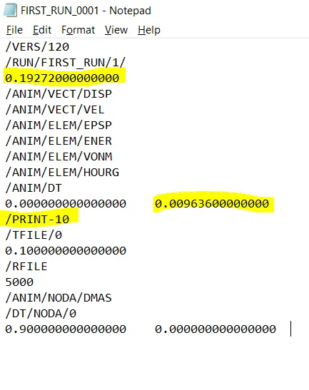
Procedure :
- After changing the values and format of engine snippet file FIRST_RUN_0001 through notepad save it
- Import the file name FIRST_RUN_0000 in RADIOSS File
- Select Analysis > Radioss > Radioss > Select yes, you'll run the simulation file
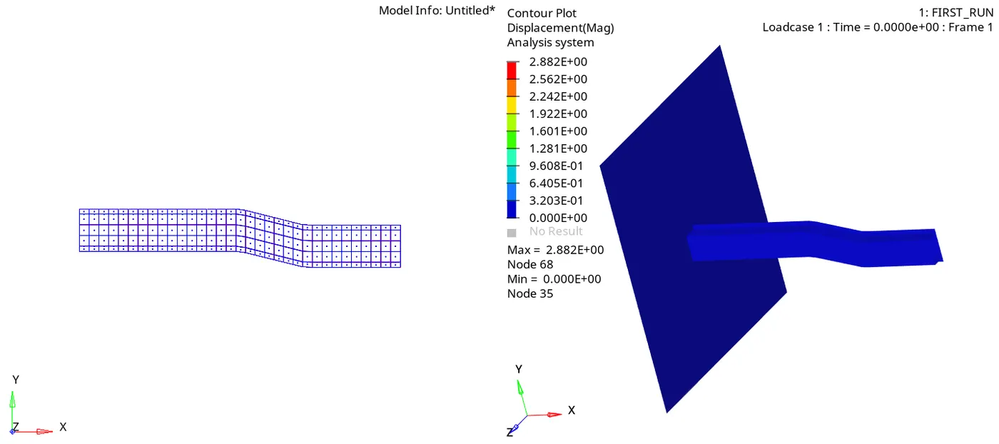
- Then by selecting Page window layout > Two window mode > Move the cursor to next window and click
- Load the FIRST_RUN.h3d model from the existing file and apply
- Select contour > Result type > and Apply it
- The GIF file shows the exact procedure we've done
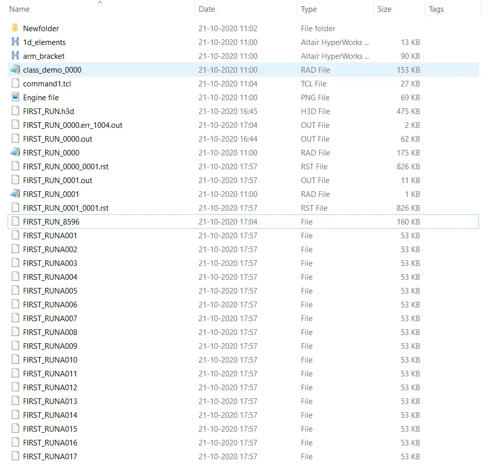
To perform Tetra 3D meshing for HOUSING & ARM_BRACKET
Procedure :
- There are three types to perform 3D meshing
- In the following procedure, we're going to proceed with Quick tetra mesh via utility tools
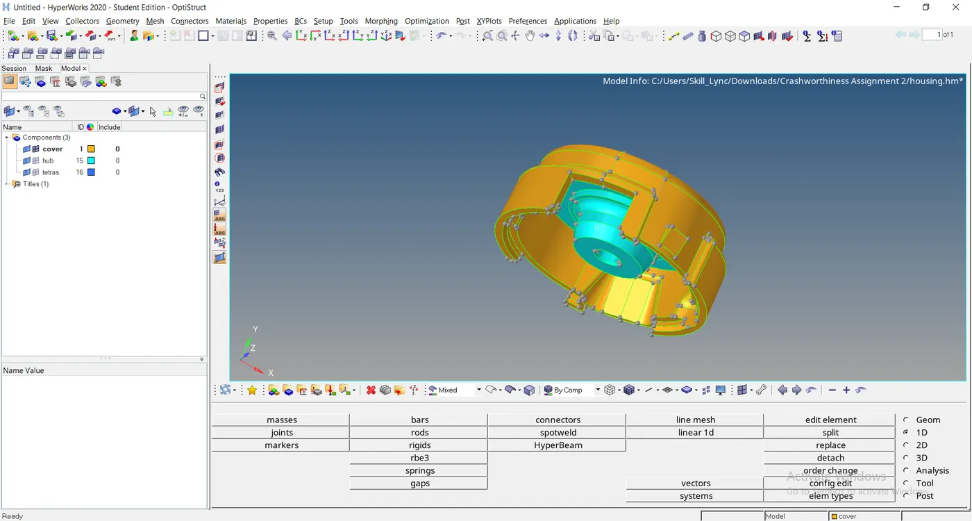
Open the file from the existing place
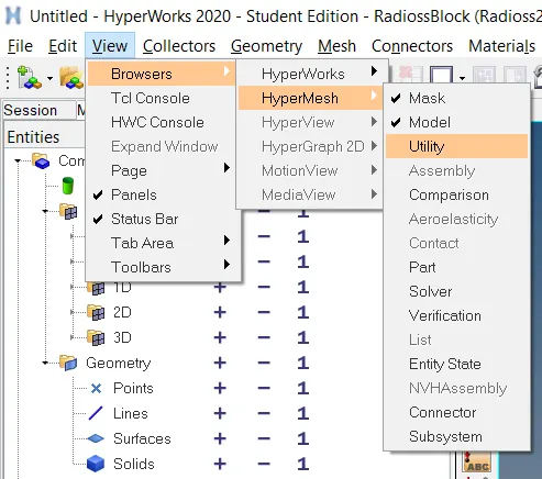
And perform the quick 3D meshing function as given
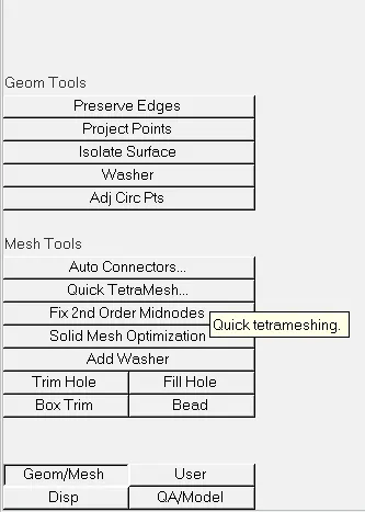
Select Geom/Mesh > Quick TetraMesh option
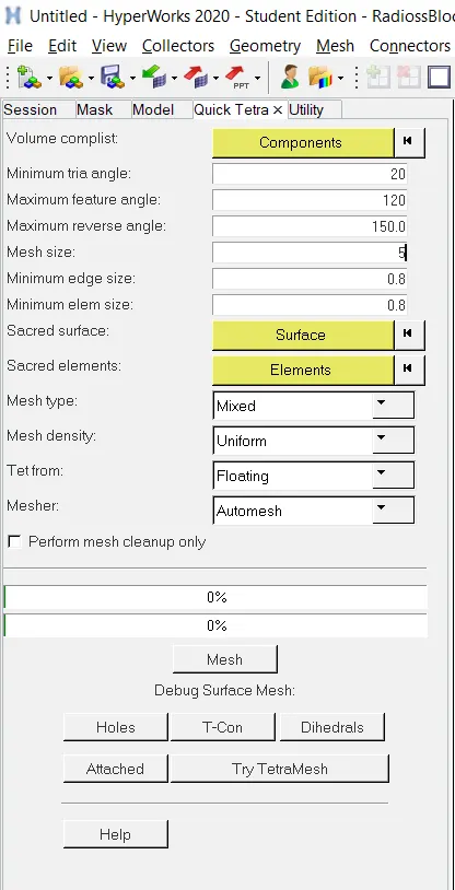
Select the Component > Edit the given data such as minimum & maximum triangle, Mesh size > And click Mesh option
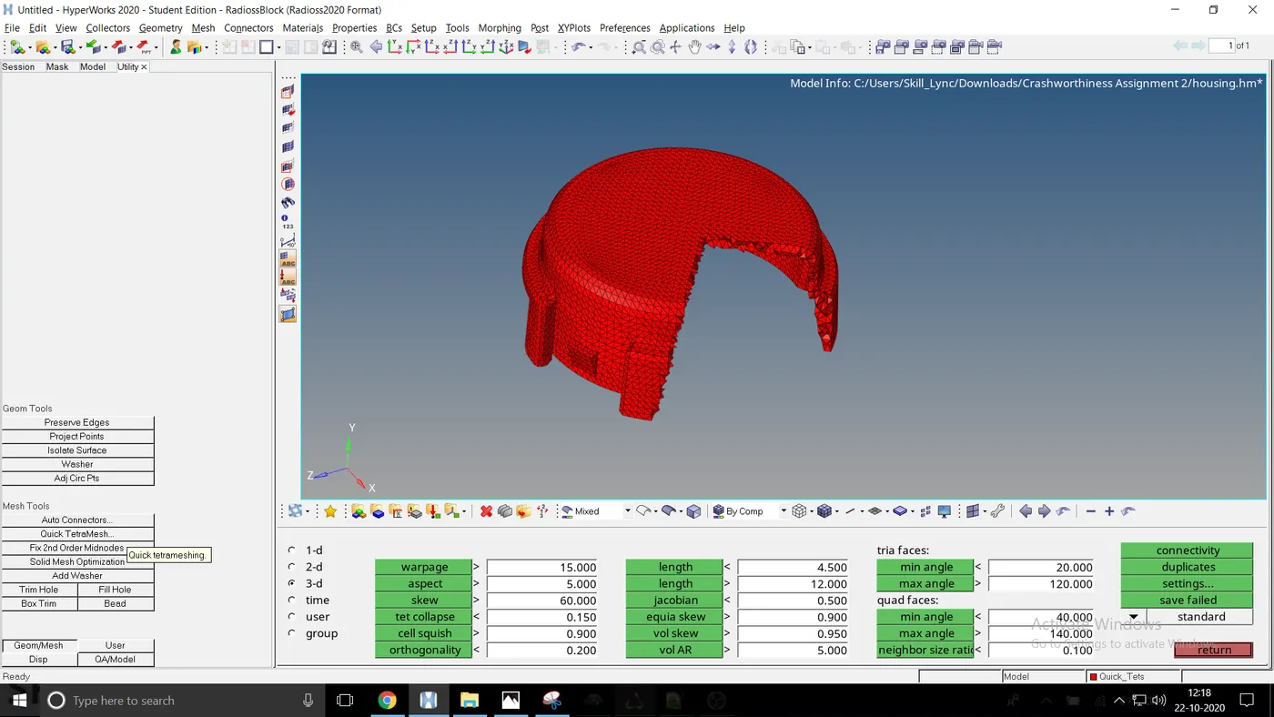
To check the failure of the components Tool > Check elements > 3-d > click the bar for any case of failure
Arm_bracket :
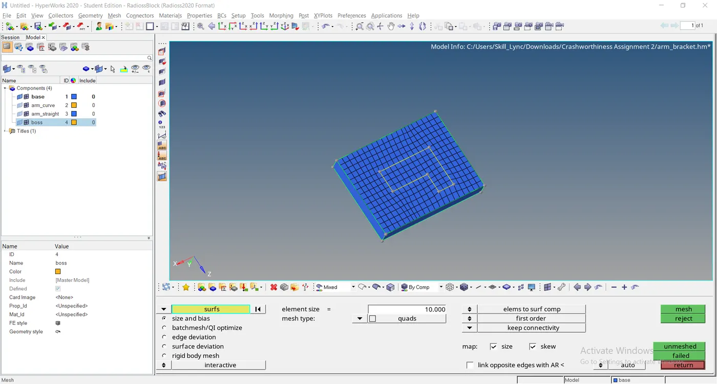
Hide the components except for base from the given file
Perform 2D meshing on the upper surface of the base
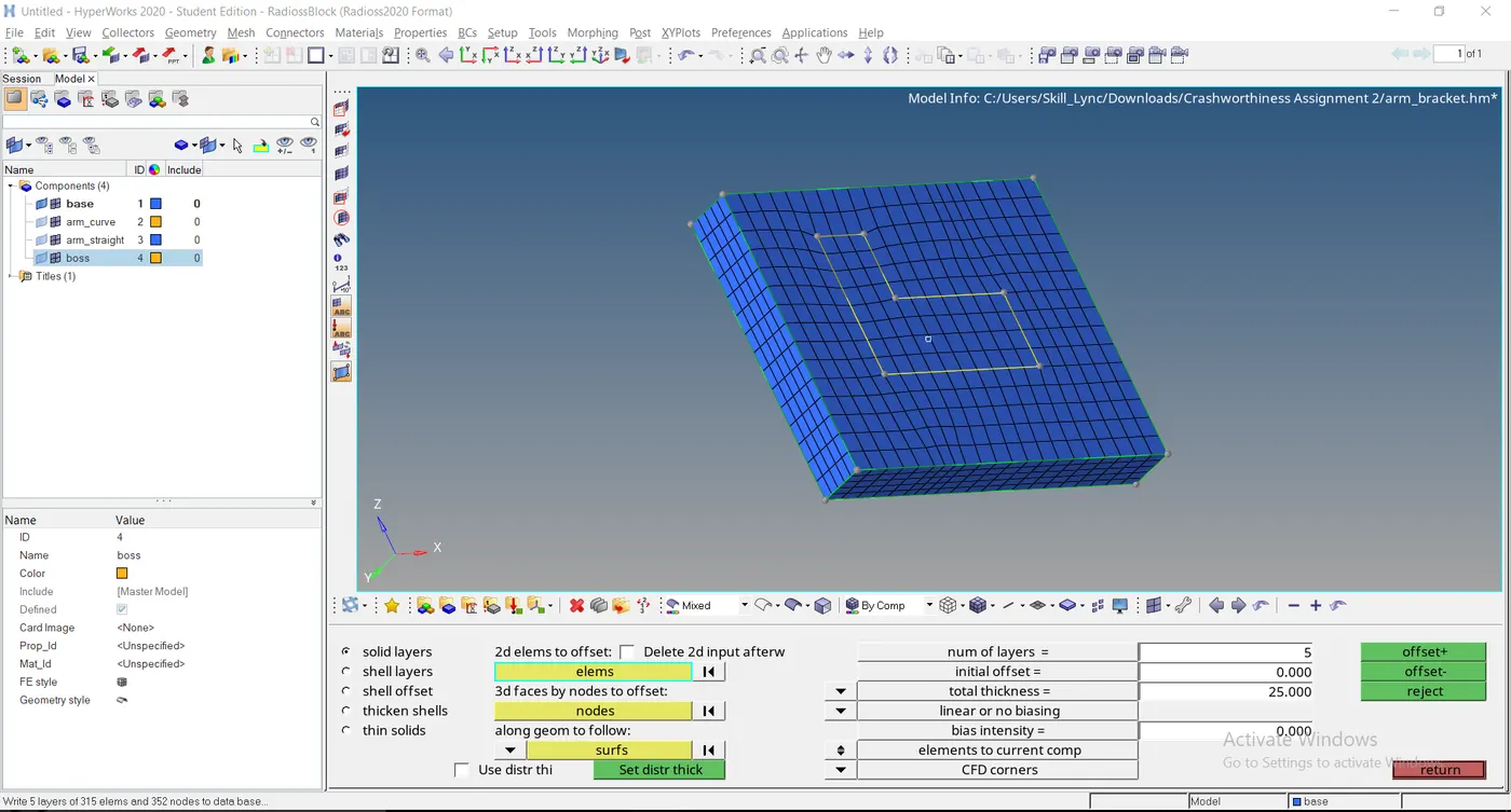
Offset the element with a total thickness of 25 and 5 layers from the solid layers
We get the amount of mesh on each side of surfaces
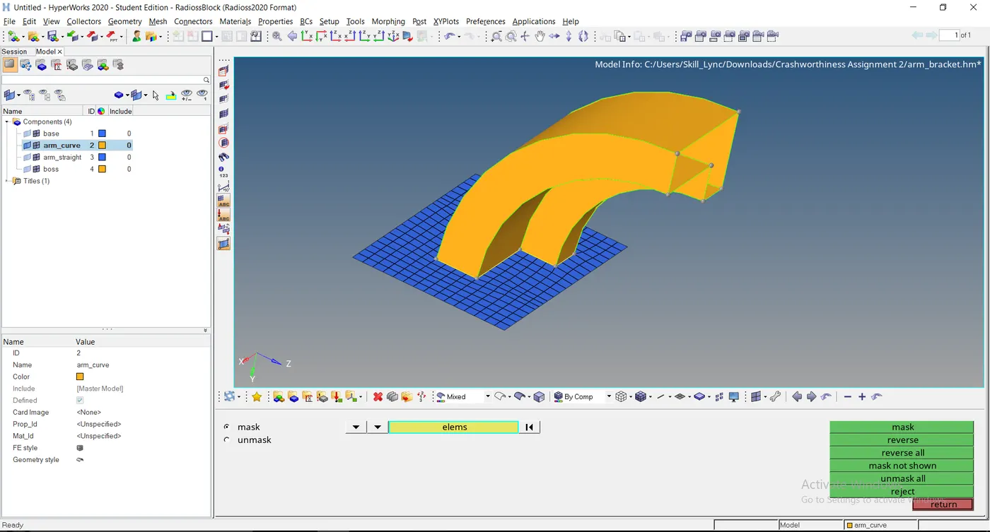
Eliminate the surface by clicking elems > by config > hex8 > select enitites > mask
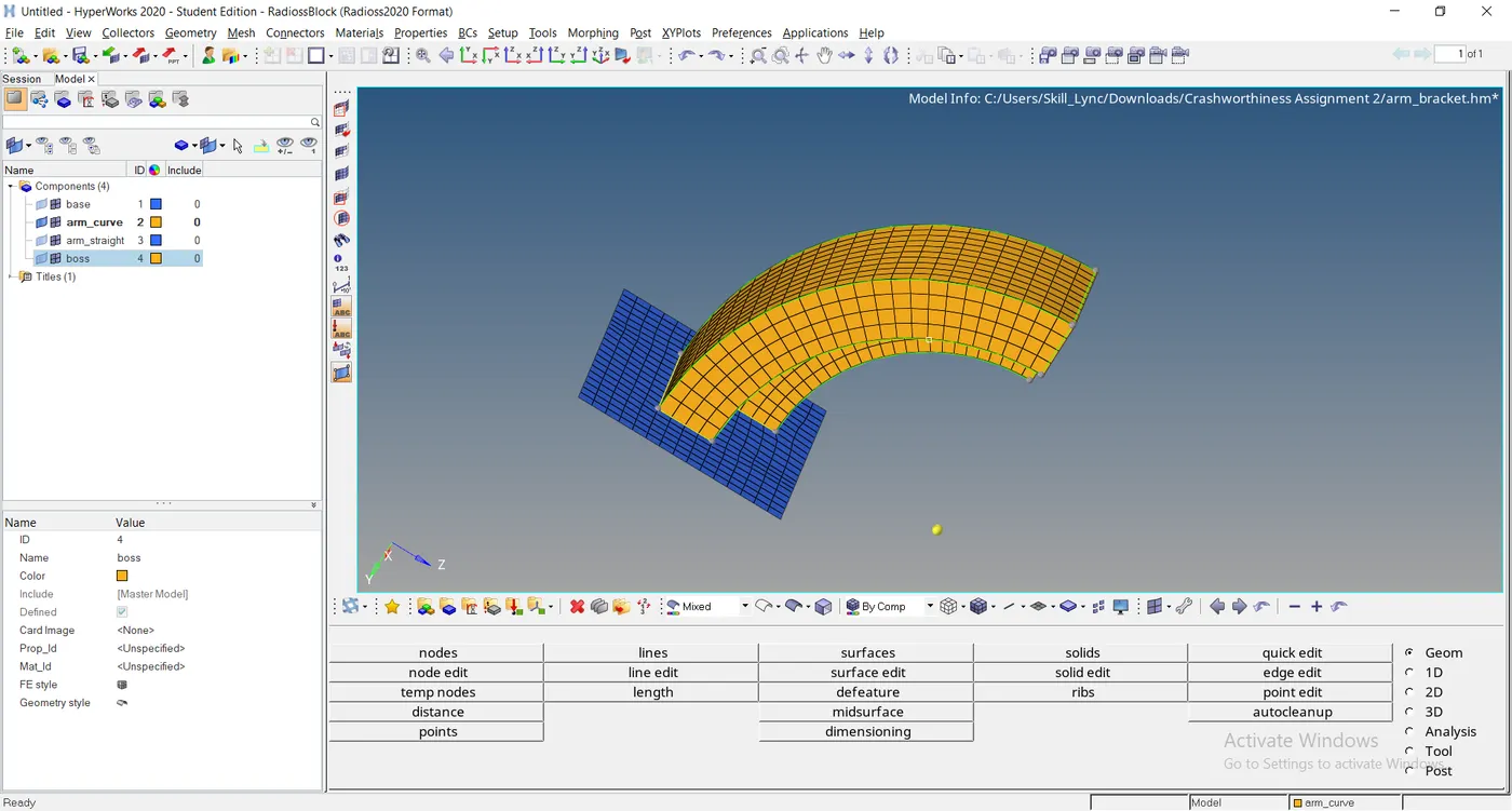
To reflect the mesh from base to arm curve, at first create a center circle from the given line
Select 3D > spin > spin geoms > select line list > edit angle 90 > select the centre node by clicking B > enter spin+
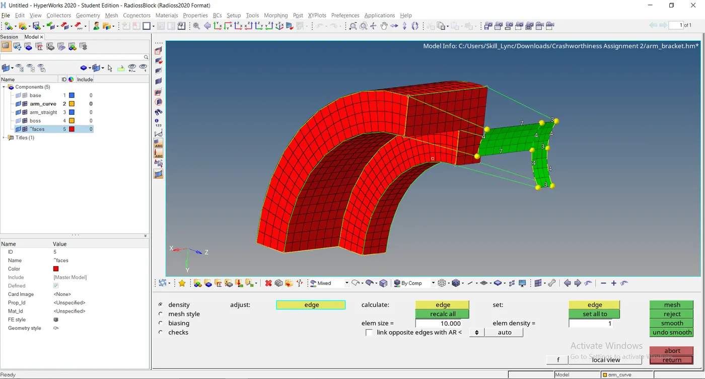
Create 2D mesh on arm straight of the surface and adjust a mesh according to the surface of the arm curve
By adjusting the mesh value we'll get the proper proportion
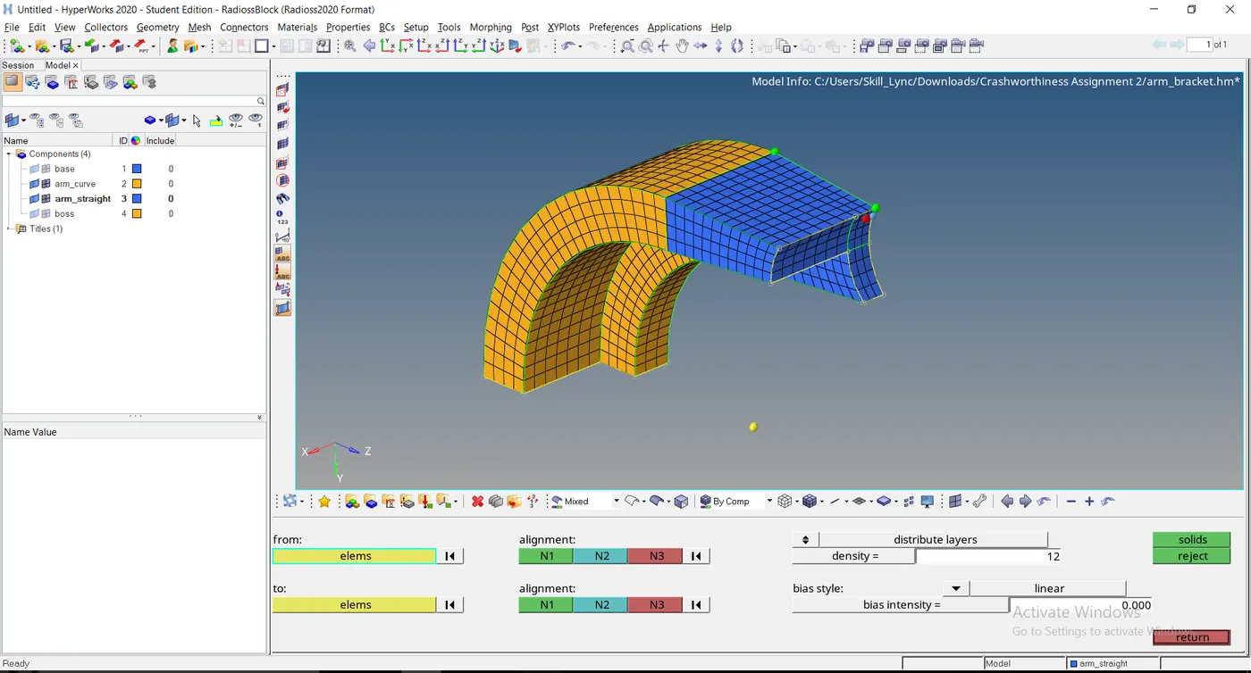
Open 3D > linear solid, Select the elements to face on both components
Select the density value to half of the distance by 12
Create nodal points and select solids
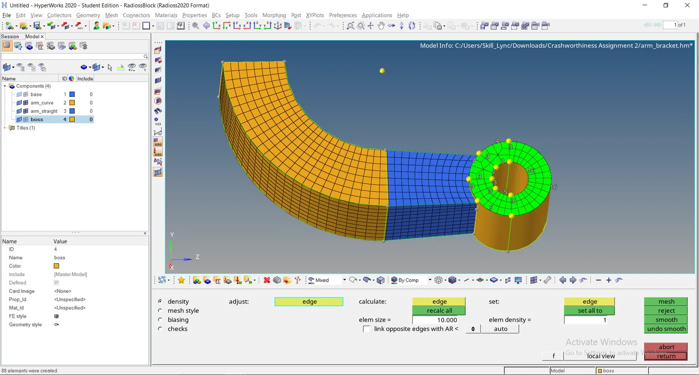
Create 2D mesh on the surface of the boss and align the mesh order accordingly
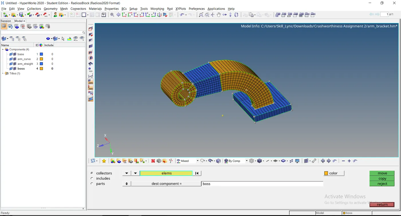
The final output of the arm bracket is finished as per the steps taken
Conclusion :
3D meshing for Housing, Arm understood and achieved
Engine simulation process understood and achieved