Week-7 Head Impact
Aim:
To perform the Head Impact Simulation and calculate the HIC value for the following cases
Objective:
- The impact simulation of a simple head against the rigid wall
- The impact simulation of the head form provided with the rigid wall
- The impact simulation of the head form with the given meshed hood
Pedestrian Head Impact
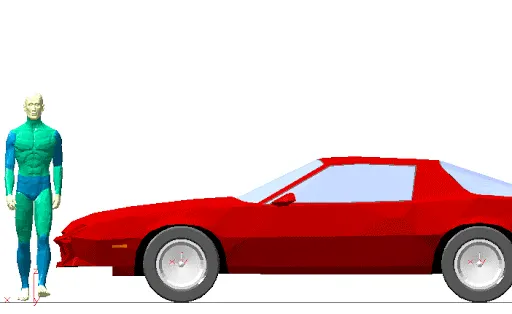
About 14 percent of all road fatalities in Europe are pedestrians, with children and the elderly being at the greatest risk. Pedestrians comprise one of the main categories of vulnerable road users, which also include cyclists and motorcyclists
Currently in India, Automotive Indian Standard (AIS) 100, Amendment 1 is used to evaluate the performance of vehicles against pedestrian safety. This standard has been harmonized from the international evaluation standard Global Technical Regulation No. 9 (GTR 9), whose purpose is to bring about an improvement in the construction of the fronts of vehicles and, in particular, those areas which have been most frequently identified as causing injury when in collision with a pedestrian or other vulnerable road user. The tests required are focused on those elements of the child and adult body most frequently identified as sustaining an injury,i.e. the adult and child head, leg
Wrap Around Distance (WAD)
When a car crashes on the pedestrian, the whole human body wraps around the front shape of the car, and the head impacts on the bonnet or the windscreen. The distance at which the head impacts on the car from the ground is called the Wrap-Around Distance (WAD). To be specific the WAD is a measurement of the distance from the ground to the head impact zone over the outer surface of the car.
The WAD is measured longitudinally in the center of the vehicle from the ground. The severity of the injury caused by the frontal crash depends on the type and shape of the vehicle, the speed of the vehicle, and the movement of the pedestrian relative to the vehicle. In addition to these parameters, the wrap-around distance plays a major role in the safety measures of a pedestrian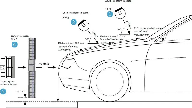
Head Injury Criteria (HIC)
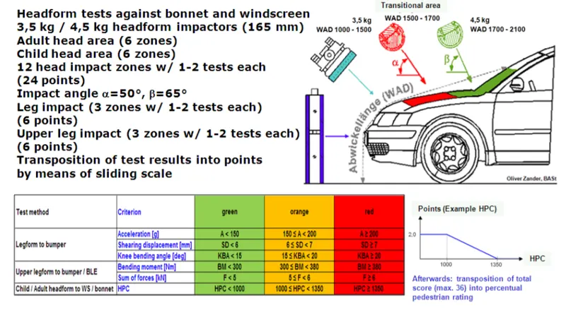
In a pedestrian-vehicle impact, the kinematics and severity of pedestrian injuries are affected by the impact locations on the vehicle and body velocities after impact. The objective of this project is to analyze the pedestrian kinematics in a pedestrian-car accident scenario and to determine the head resultant acceleration.
The equation used for the measurements of the head injury of the whole model for the pedestrian head impact was Head Injury Criteria (HIC). It has been used to predict the risk of engine hood to a pedestrian during the collision
- `HIC = max_(t_1,t_2) {[1/(t_2-t_1)int_(t_1)^(t_2)a(t)dt]^2.5(t_2-t_1)}`
whereas:
- a refers to the resultant acceleration
- `t_1, t_2` refers to the start and end of the recording when HIC is at maximum. Values of HIC at the time interval `t_1-t_2`
Abbreviated Injury Scale (AIS)
- Slight damage to the brain with headache, dizziness, no loss of consciousness, contusion
- Concussion with or without skull fracture, less than 15 minutes of unconsciousness, detached retina, face, and nose fracture
- Concussion with or without skull fracture for more than 15 minutes of unconsciousness without severe neurological damage, multiple skull fractures, loss of vision, multiple facial fractures, cervical fracture without damage to the spine
Procedure:
Case-1 Simple head impacting against the rigid wall
- In this model, I've used kg,m,s as units
Import
- The given keyword file of the simple head FE model is opened using LS-PrePost, File`rarr`Open`rarr`LS-Dyna Keyword File
Section
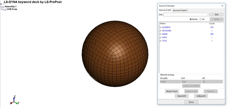
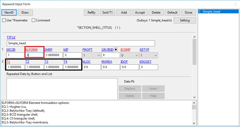
- The given simple head-form is meshed using the 2d elements. I've defined them as the SECTION_SHELL card
Here,
- SECID: Section ID. SECID is referenced on the *PART card. A unique number must be specified
- ELFORM: Element formulation options. It is done for calculations=2 Belytschko-Tsay (default)
- SHRF: Shear correction factor which scales the transverse shear stress=1
- NIP: Number of through-thickness integration points=2
- T1,T2,T3,T4: Shell thickness=1m
Material
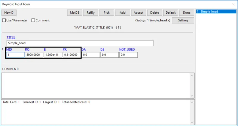
- For the material card head-form, I'm using the MAT_ELASTIC to be bounced. Properties I've used are Nickel (Aluminium)
Here,
- MID: Material identification. A unique number or label not exceeding 8 characters must be specified
- RO: Mass density
- E: Young's modulus
- PR: Poisson's ratio
Part
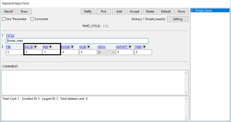
- The material and section are assigned to their respective part ID
Rigid wall
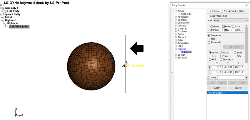
- The rigid wall is created at a distance to the right of the simple head model along the x-axis direction
Boundary conditions
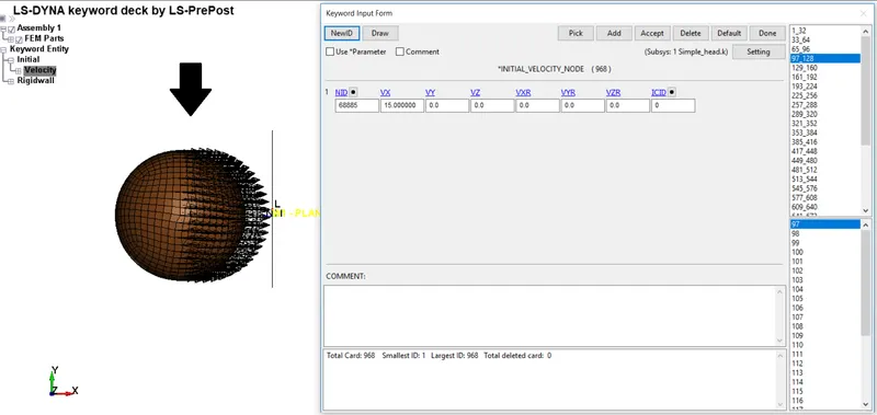
- The simple head model is assumed to be impacting the rigid wall at a velocity of 15 m/s in the negative X-direction towards the rigid wall
Control
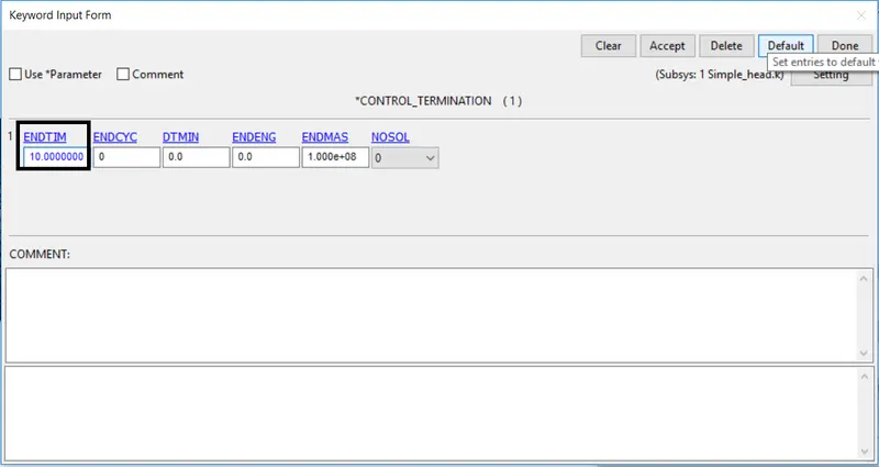
- The Control_Termination function is used to define the running/end time of the simulation. The termination time is set for 10 ms
Database
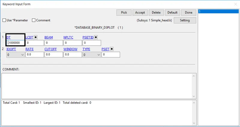
- The time step value of 0.5 ms is given for the BINARY_D3PLOT to know the animated file
Results
CONTOUR PLOTS OF VON MISES STRESS:
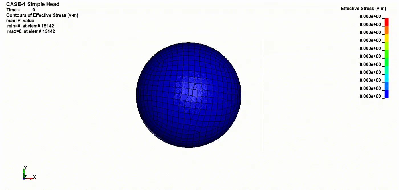
- The stress values are higher at the moment of impact and lower with fluctuations after the contact as the material is purely elastic.
There is no significant deformation occurs in the simple head geometry
Case-2 Pedestrian Head-form impacting against the rigid wall
The given pedestrian head-form includes section ID, MAT ID with respect to the Part ID. The units they've given kg, mm, ms
Also, Controls, Contacts, and Constrained nodes keywords have been covered with the model
Transformation
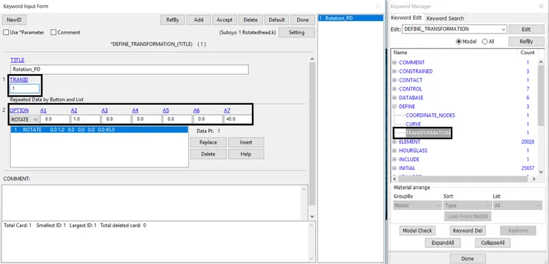
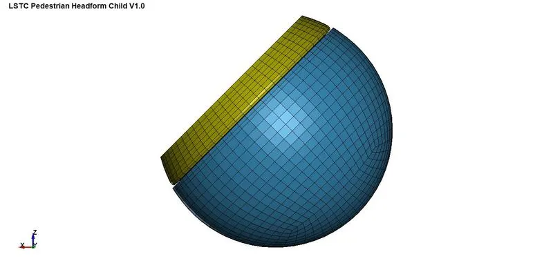
- Open LS-Dyna without opening/importing any of the keyword models. The model needs to be rotated about `45^o` along the Y-axis to replicate the Euro NCAP impact simulation
- DEFINE_TRANSFORMATION keyword is used to transform direction, TRANID=1 by switching the OPTION`rarr`ROTATE along Y-axis as (A2=1) by `45^o` (A7=45)
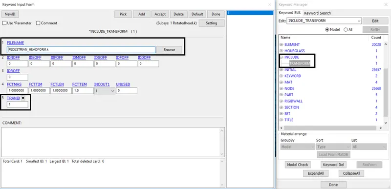
- INCLUDE_TRANSFORM keyword is done to specify the model from Browse to be transformed along the direction. Save as a new model and closed it
- By opening the new model the LS-Dyna reads the keyword determined and present the default model according to the transformation defined
Rigid wall
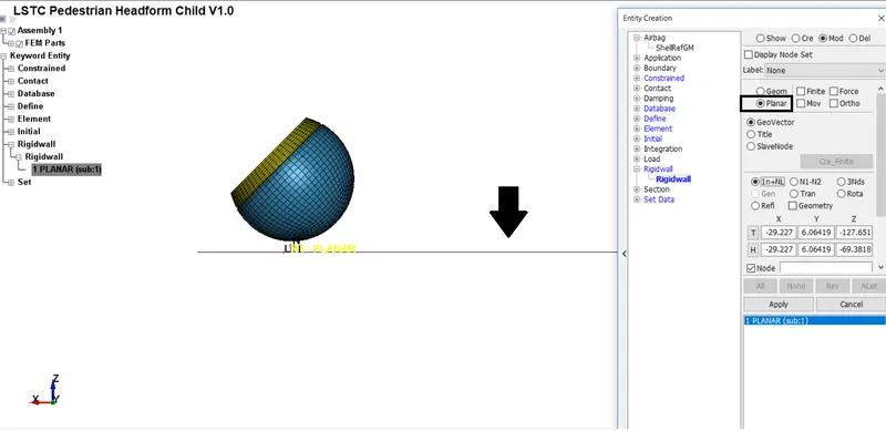
- The rigid wall is created at a distance to the end of the simple head model along the negative z-axis direction
Boundary conditions
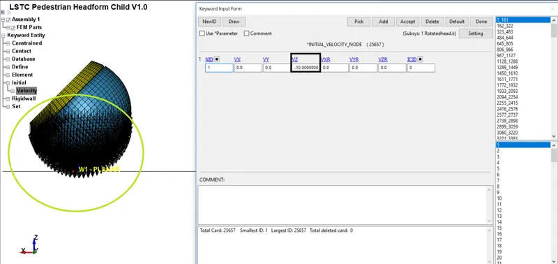
- As per Euro NCAP standards, the initial velocity is taken as 10 mm/ms at an angle `45^o`
Control cards
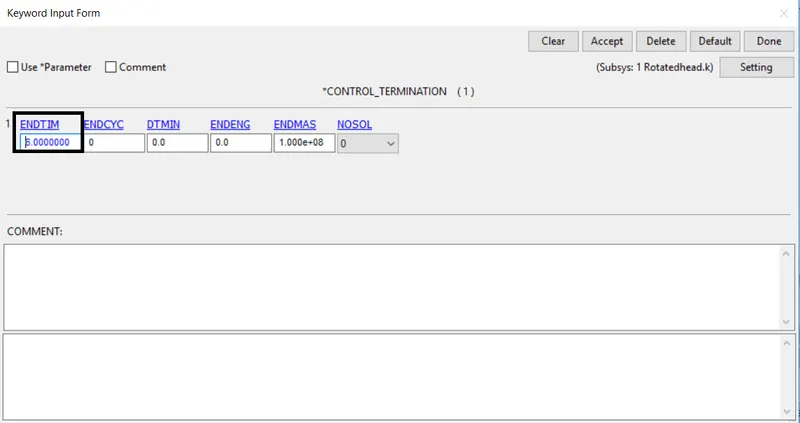
- The Control_Termination function is enabled to specify the end/total time of the simulation. The termination time is set for 6 ms
Database
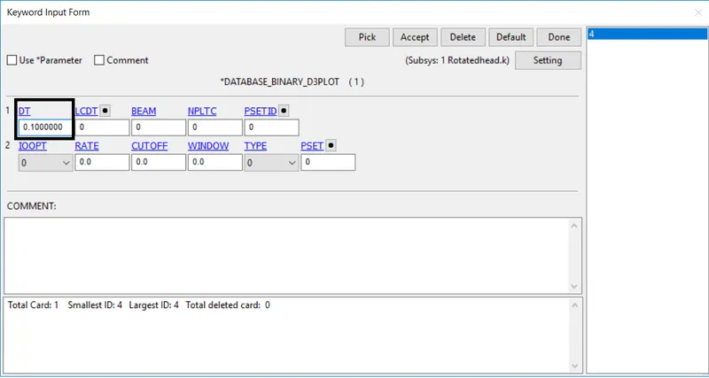
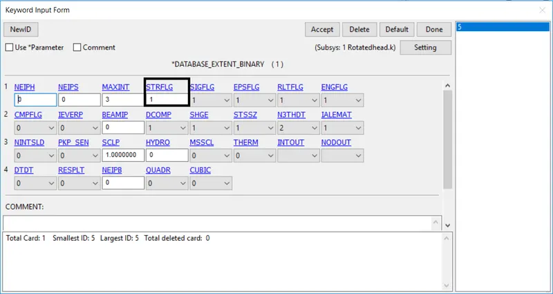
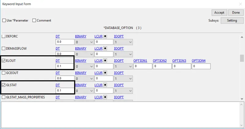
The time step value of 0.1 ms is given for
- BINARY_D3PLOT
- BINARY_EXTENT (STRFLG=1)
- DATABASE_ASCII (GLSAT, NODOUT, and RWFORC)
Results
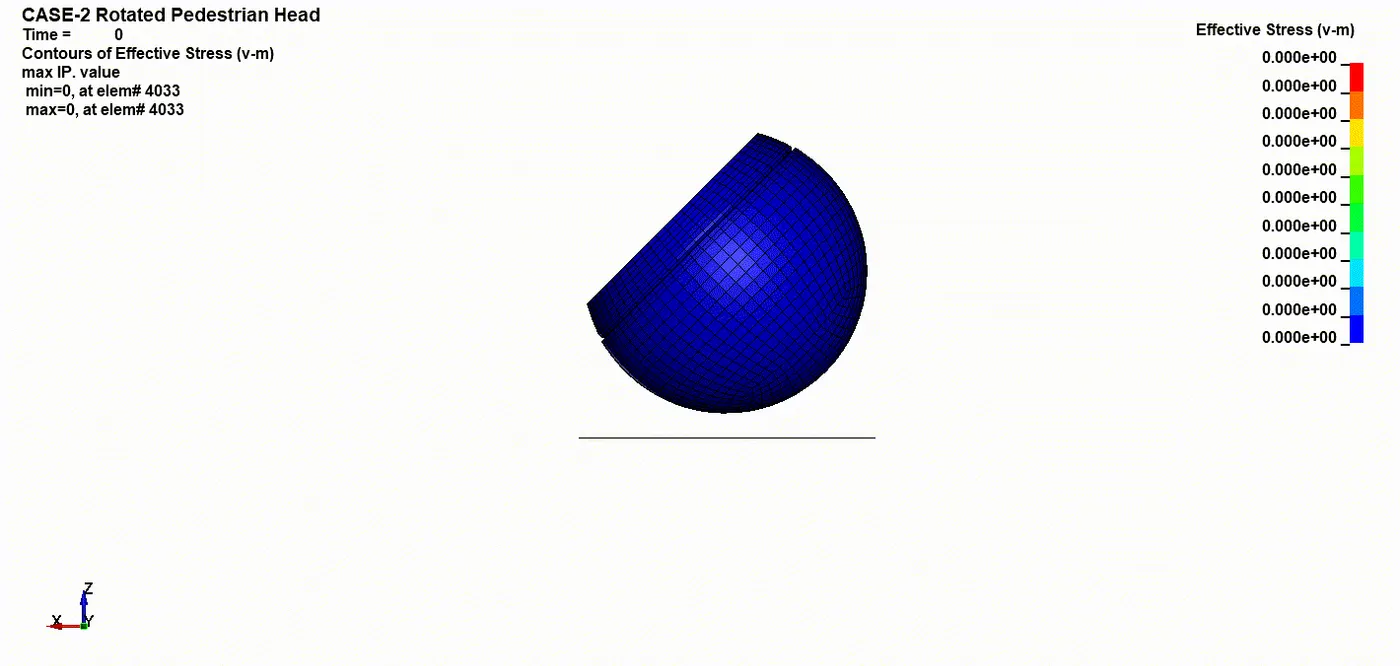
CONTOUR PLOTS OF VON MISES STRESS:
- The animation depicts stress behavior in head form geometry after the impact. The material properties for this geometry are pre-defined and different compared to the simple head form.
So, it shows different behavior. There is significant deformation in the geometry after the impact
GRAPH:
Stress/Strain
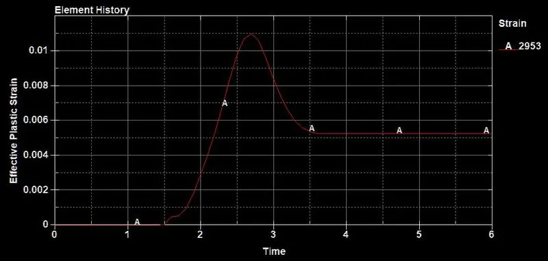
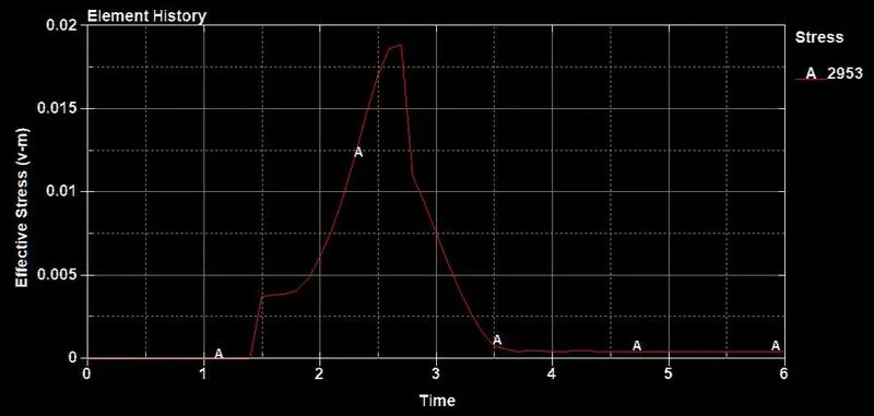
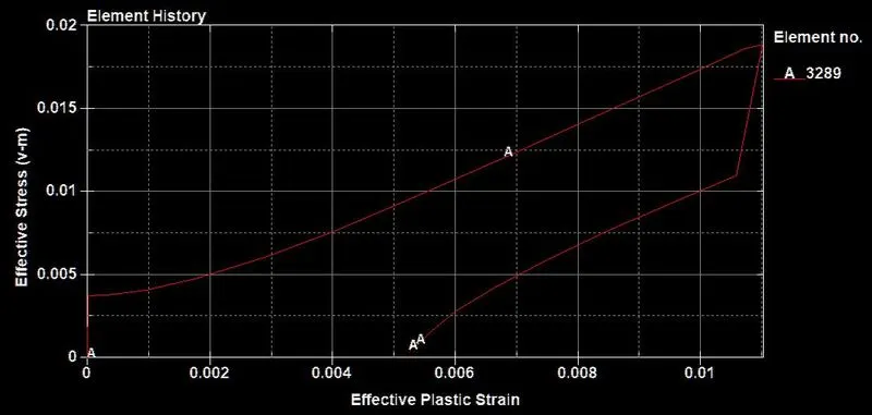
- The stress/strain plotted at max around 0.0110/2.70ms (Strain) and 0.0189/2.70ms
- The second graph depicts as the head contact with the rigid wall it is raised rapidly and returning back to the state where head moved aside
Accelerometer (HIC)
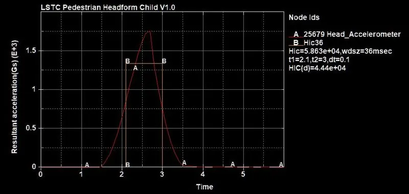
- The above plot reveals the HIC-36 value for Pedestrian head impacts Hood. If the time interval used to estimate the HIC value is lesser than 15ms, both HIC15 and HIC36 result in the same.
If the time interval is larger than 15ms then HIC36 is higher. The HIC-36 value for head form impact on the hood is `5.863e^(+04)`
Case-3 Pedestrian head-form impacting against the hood:
Import
- The given keyword file of the Meshed hood FE model is opened using LS-PrePost, File`rarr`Open`rarr`LS-Dyna Keyword File
Section
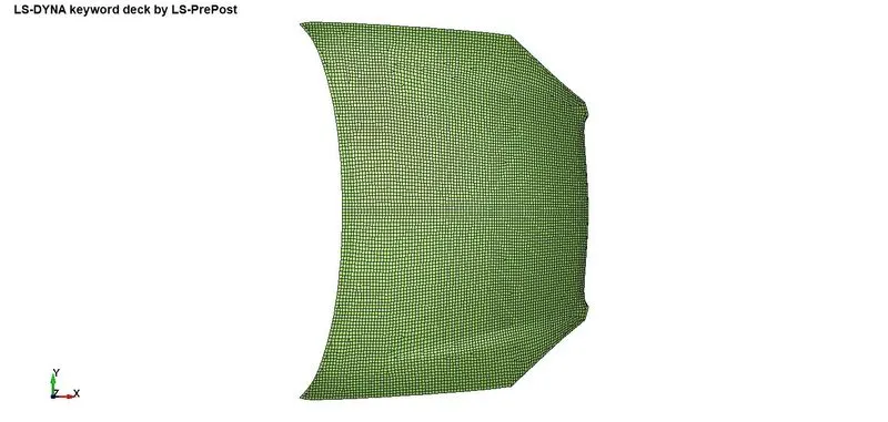
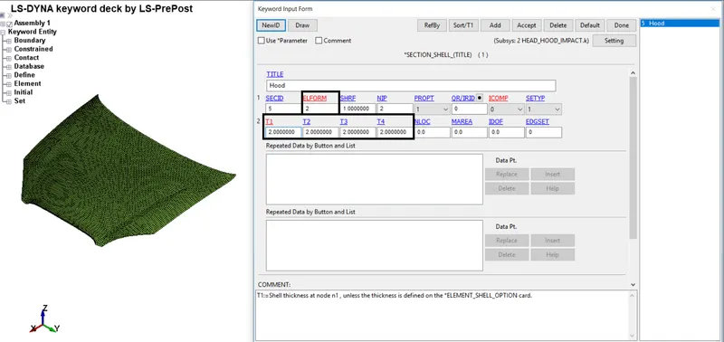
- The given hood is meshed using the 2d elements. I've defined them as the SECTION_SHELL card, Thickness T1-4 `rarr` 2mm
Material
- For the material card meshed hood, I'm using the MAT_PIECEWISE_LINEAR_PLASTICITY(24). Properties I've used are Aluminium
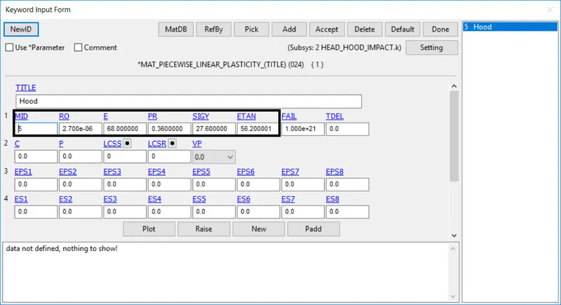
Here,
- MID: Material identification. A unique number or label not exceeding 8 characters must be specified
- RO: Mass density
- E: Young's modulus
- PR: Poisson's ratio
- SIGY: Yield stress
- ETAN: Tangent Modulus
Part
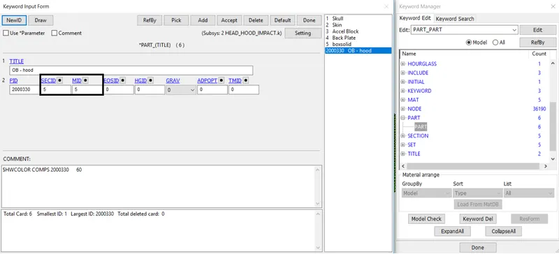
- The material and section are assigned to their respective part ID
Include/Include_transformation
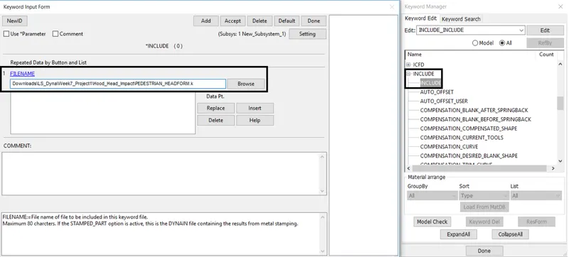
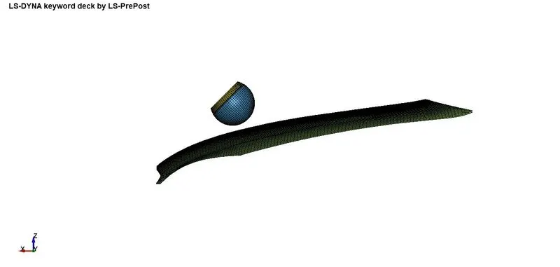
- On the other side transform the pedestrian head as transformed before without creating a rigid wall
- Using Include_Include select the transformed pedestrian model to be inserted at meshed hood
- Once the meshed model is opened the include keyword involves the transform model upon it
Boundary conditions
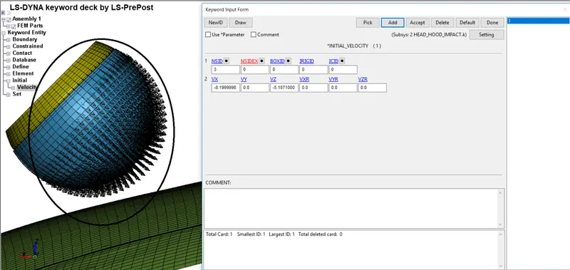
- As per Euro NCAP standards, the initial velocity is taken as 10 mm/ms at an angle `45^o`.
Using`sintheta,costheta` I've found the displacement value i.e, X-axis and Z-axis velocities are taken as -8.19 mm/ms and -5.10 mm/ms respectively
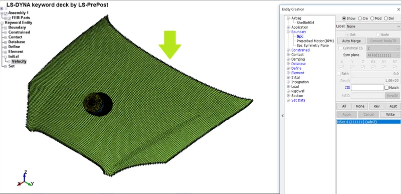
- Using create entity option the nodes on the outer edges of the hood are selected and constrained along all the translational and rotational motion using the option Boundary_SPC_Set
Contact
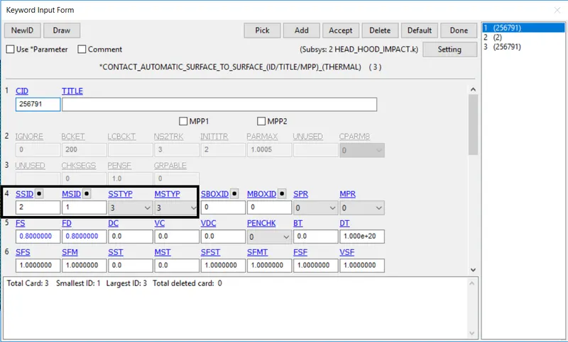
- The CONTACT_AUTOMATIC_SURFACE_TO_SURFACE card is used again to define contact between hood and head form. The child head form model is taken as a master and hood as a slave
Control
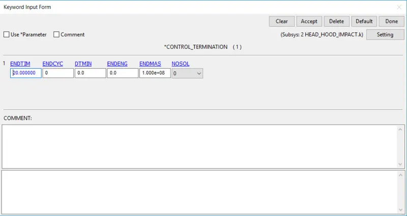
- The Control_Termination function is enabled to specify the end/total time of the simulation. The termination time is set for 20 ms
Database
The time step value of 0.1 ms is given for
- BINARY_D3PLOT
- BINARY_EXTENT (STRFLG=1)
- DATABASE_ASCII (GLSAT, NODOUT, and RWFORC)
Results
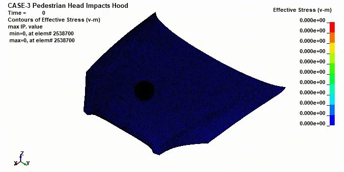
CONTOUR PLOTS OF VON MISES STRESS:
- This animation explains that the hood deforms more than the pedestrian head form compared to the second case.
This is because the elastoplastic material behavior has been defined to the hood, this material tends to deform elastically till the yield point and later deforms plastically following that
GRAPH:
Effective Plastic Strain
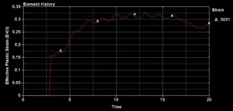
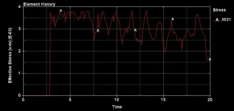
- The stress/strain plotted at max around 0.000328/13.2ms (Strain) and 0.000382/11.7ms
Accelerometer (HIC)
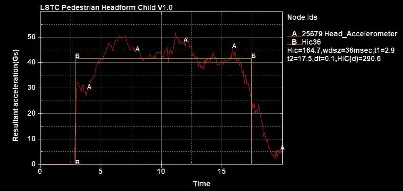
- The above plot reveals the HIC-36 value for Pedestrian head impacts Hood. If the time interval used to estimate the HIC value is lesser than 15ms, both HIC15 and HIC36 result in the same.
If the time interval is larger than 15ms then HIC36 is higher. The HIC-36 value for head form impact on the hood is 164.7
Manual calculation,
- `HIC = max_(t_1,t_2) {[1/(t_2-t_1)int_(t_1)^(t_2)a(t)dt]^2.5(t_2-t_1)}`
- From the plot,The average value of acceleration for the time interval of `t_1=2.9 ms` and `t_2=17.5 ms`.So, the average acceleration from the graph is taken as around 41.7Gs
`HIC = (at)^2.5(t_2-t_1)e^-3`
`HIC = (41.7)^2.5(17.5-2.9)e^-3`
`HIC = (11228.97)(14.6)e^-3`
`HIC =163942.962 *e^-3`
`HIC rArr 163.942`
Comparison Case 2 vs Case 3
From the above case, the Pedestrian Head form impacts the hood is to analyze and learn the real-life situation.
- The standard model of the pedestrian head form provided with the Ogden material was used, Since the rigid wall is undeformable the total stress is transferred to the head and deforms the geometry of the head
- For the final case, the hood was defined as a piecewise linear plastic material (Aluminium) which is a deformable material model. So during the impact, the hood deforms significantly by reduces stress and strain on the head form. Thus the HIC value reduces comparatively to the previous case
Conclusion:
An FEA model Head Impact Simulation is analyzed and understood from the following cases. Also, calculated the HIC value and demonstrated the manual method