Week - 4 - Crash Box Simulation
Objective:
To perform Crash Box Simulation with respected data and to plot the deliverables
Procedure:
The given model consists of two parts i.e, Crash box(Meshed). Few major keywords need to implement to progress with the simulation method without any fail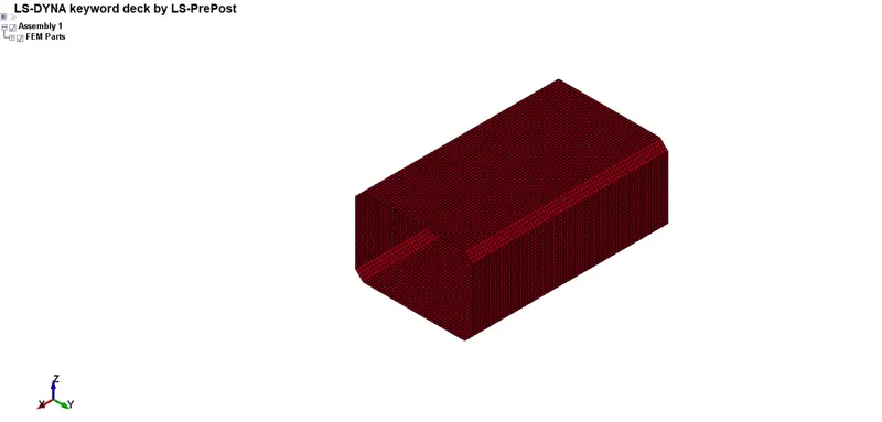
Rigid wall
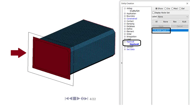
- For an infinite wall, create Rigidwall using Create Entity `or` Rigid wall `rarr` Planar. The rigid wall is created since it is an undeformable object, as we are going to concentrate on the result of crash box analysis
Material
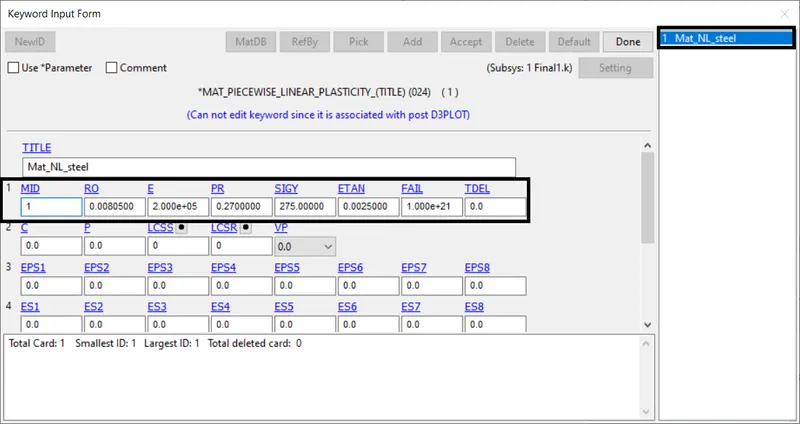
- For crash tube, we are assigning Aluminum properties
One of the most robust models is MAT_024 (PIECEWISE_LINEAR_PLASTICITY). This material model is recommended as a starting point for elastic-plastic simulation of metals and general plastics since it can also handle viscoelastic behavior (i.e., strain-rate dependency). This material Type 24, which is an elastoplastic material with arbitrary stress
Section
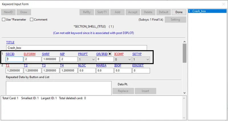
- We are using Shell elements for the part Crash Box. Since the crash box is hollow meshed we're lead to use SECTION_SHELL
Part
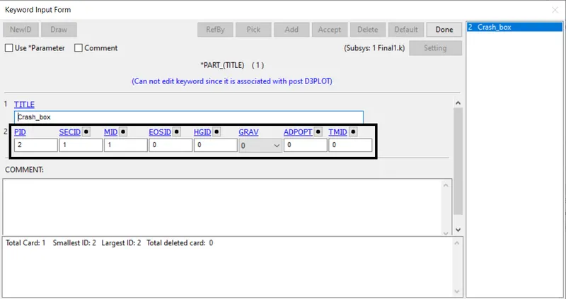
- The respected SECID, MID is assigned to the Part_ID to ensure the properties
Contact
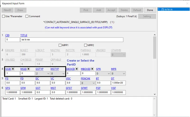
- Since the Box is crashed onto the Rigidwall. We need to create a contact between the Crash box and the Rigid wall or else the box would pass through the wall. We are going to use the contact called AUTOMATIC_SURFACE_TO_SURFACE.
- A penalty algorithm is used for numerical springs to prevent the penetration of nodes of one surface into another. The Crash box is set to be slave nodes and Rigid wall is assumed to be master
Initial Velocity
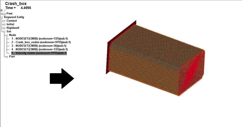
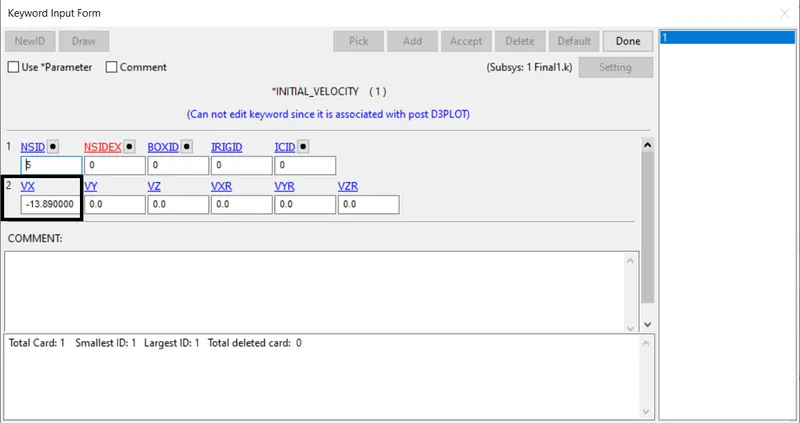
- An INITIAL_VELOCITY_NODE is defined to move the Box to make contact(crashed) with the wall. In such a way we could plot the graph value using the simulation progress
Control cards
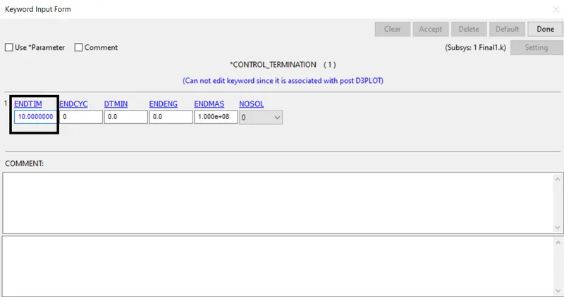
- Control_Termination is to define the simulation end time. It is set to 10 ms
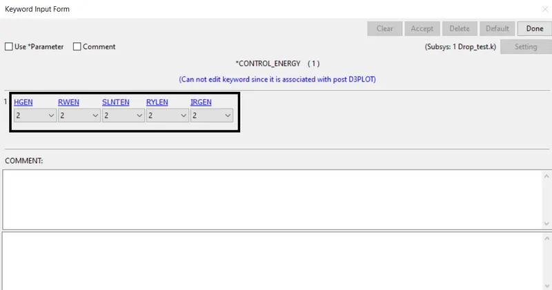
- Control_Energy is provided to control the energy dissipation
Database
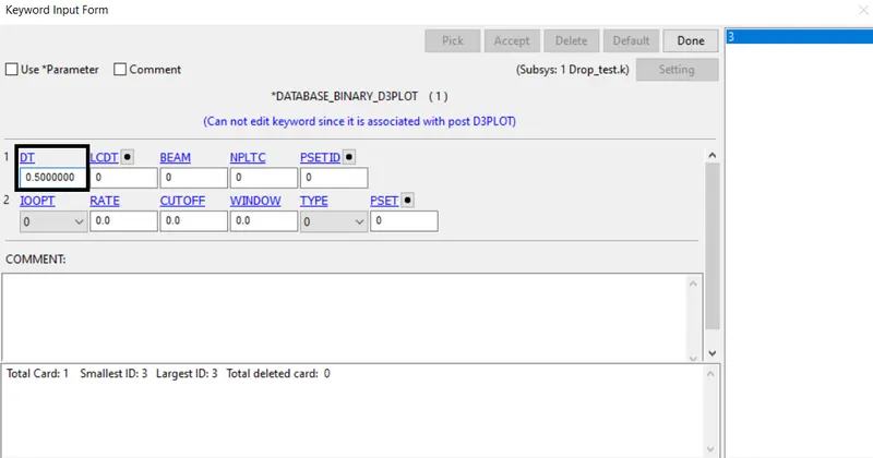
- BINARY_D3PLOT - It defines the frequency at which the animation file is to be created and is set to 0.5ms
- ASCII_option keyword
The output request in ASCII format, The following keyword are activated
ELOUT Element Data
GLSTAT Global Data
MATSUM Material Energies and
SLEOUT Sliding Interface Energies
Constrained (Optional for Mass)
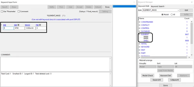
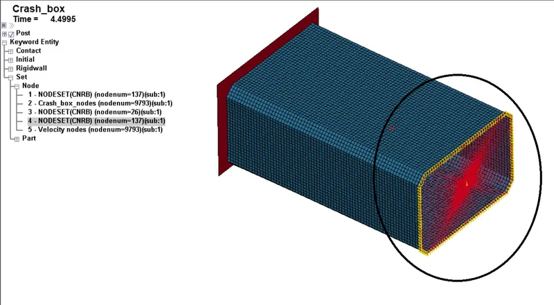
- Nodal rigid body (CNRB) is referred to as calculating the sum of nodes to the single Master node. In such a way it is created to provide the mass to the body
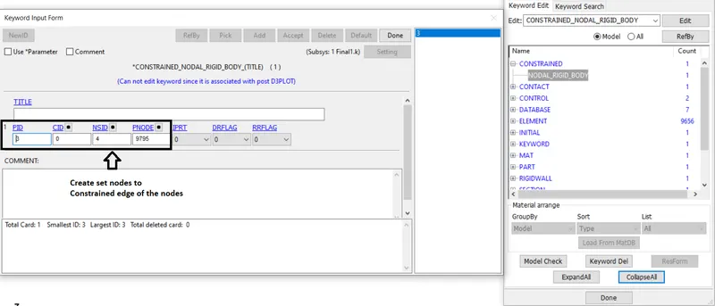
- The mass value is added to the master node of CNRB of the body. In such cases, only the box will be crushed on behalf of mass value
Model checker
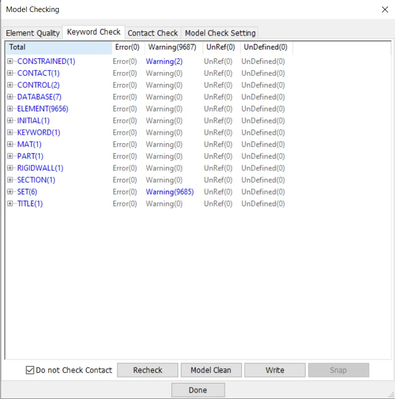
- The model checker is given to check the simulation procedure to proceed. Open the model checker under the keyword manager
Output
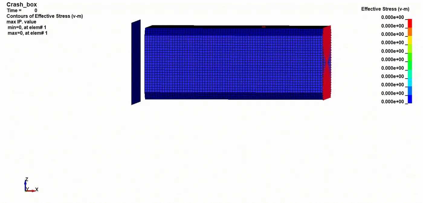
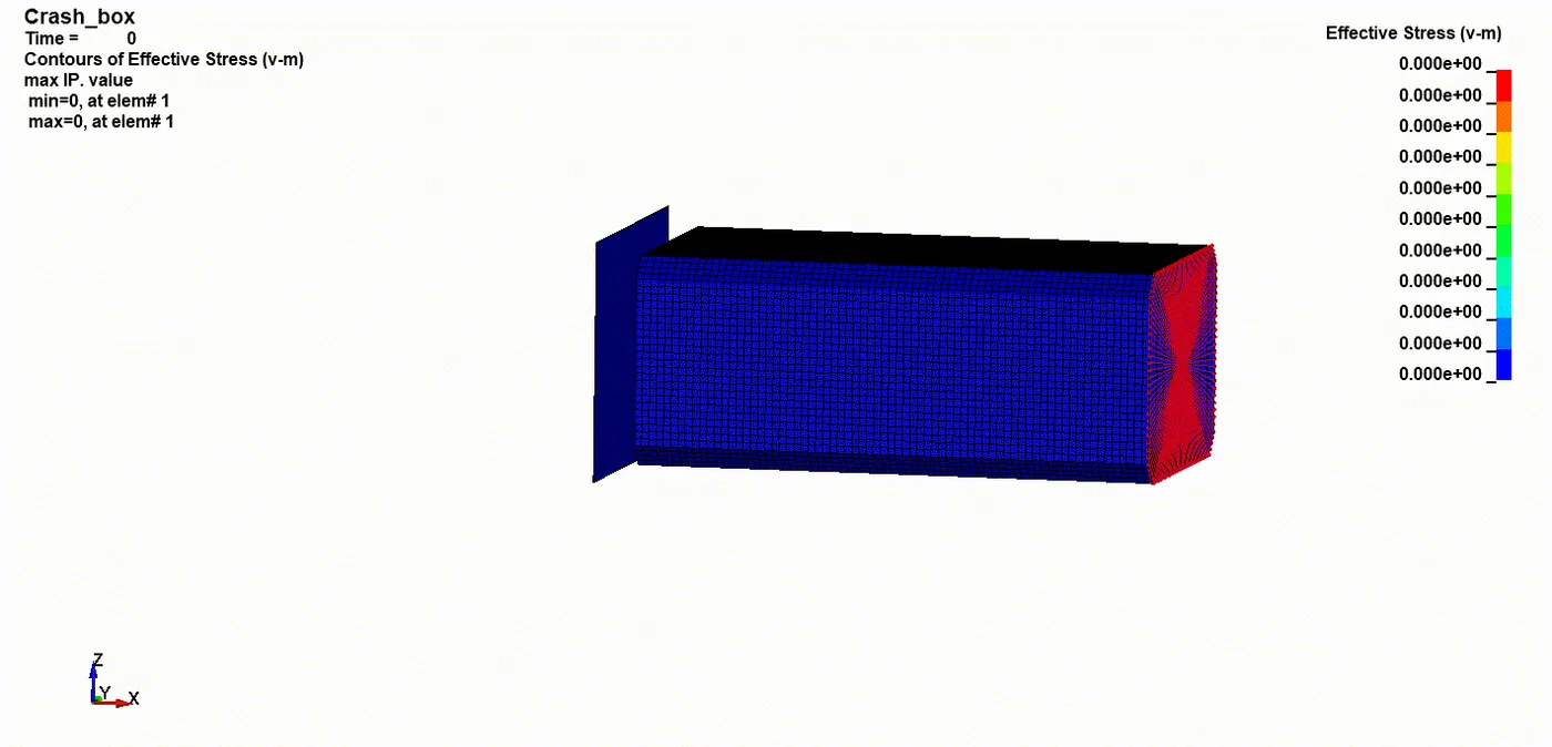
Von Mises Stress (1P2mm)
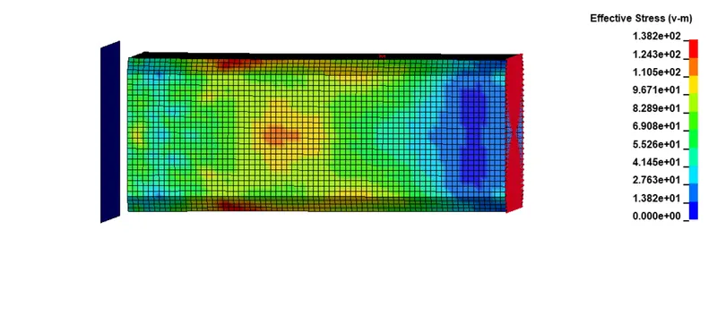
- The maximum stress attained on this 1.2mm thickness of crash tube analysis almost `1.382e^02`. As the tube crushes the stress get peaked exceed its maximum value
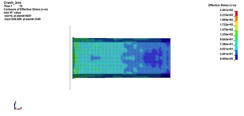
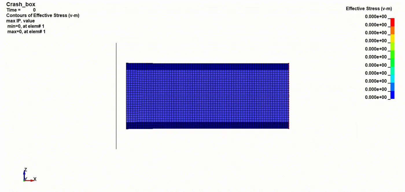
Von Mises Stress (1P5mm)
- The maximum stress attained on this 1.5mm thickness of crash tube analysis almost `1.382e^02`. As the tube crushes the stress get peaked exceed its maximum value
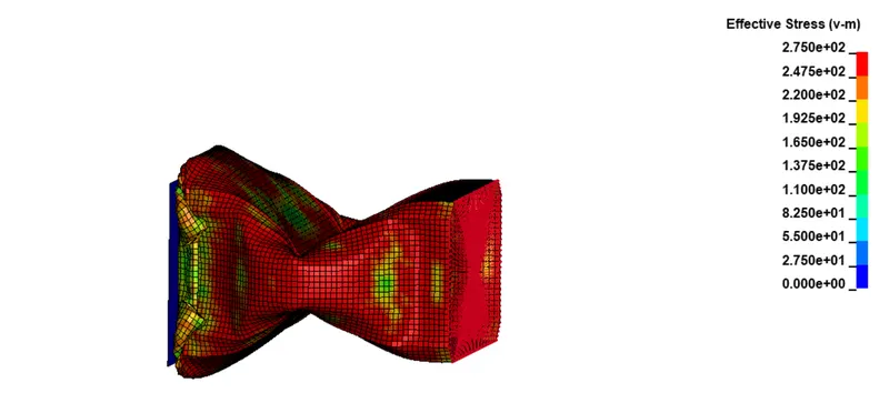
Von Mises Stress-Mass added(1P2mm)
- The maximum stress attained on this 1.2mm thickness of crash tube analysis almost `1.382e^02`. As the tube crushes the stress get peaked exceed its maximum value
Graph curve
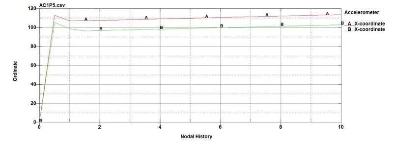
Accelerometer
- Plotting difference between 1.2mm(red) and 1.5mm(green) thickness of one point nodal from crash tube analysis
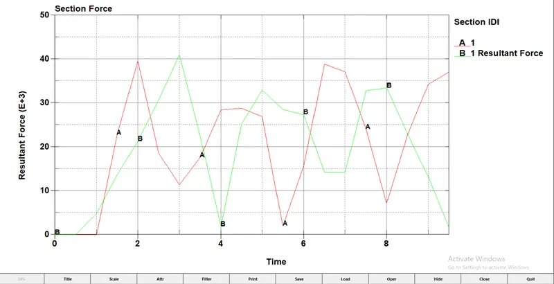
Cross-sectional Force
- Plotting difference between 1.2mm(red) and 1.5mm(green) thickness of sectional force at middle from crash tube analysis
Energy Graph
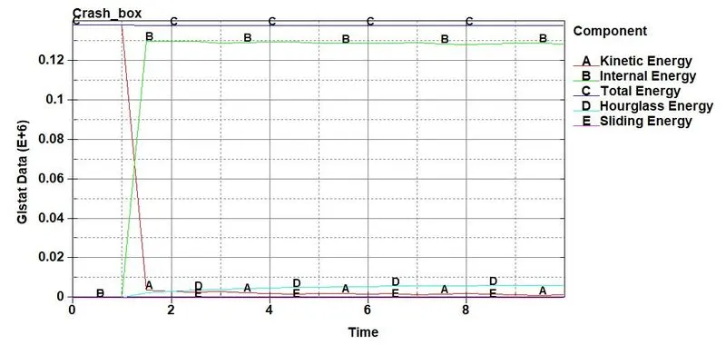
- For 1.2mm The Kinetic energy `1.27e^03`(Redline) of the Tube drops down as it hits the Rigid wall and at the same time Internal energy `1.33e^05`(Green line) is gained by the Crashing of the tube due to impact
- The Total Energy`1.38e^05` (Blue line) is a Straight line with no deflection is directly proportional to the slight increase of Hourglass energy also with Sliding energy
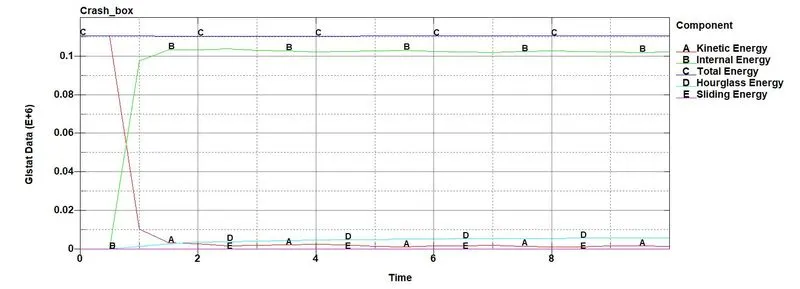
- For 1.5mm The Kinetic energy `1.30e^03`(Redline) of the Tube drops down as it hits the Rigid wall and at the same time Internal energy `1.30e^05`(Green line) is gained by the Crashing of the tube due to impact
- The Total Energy`1.41e^05` (Blue line) is a Straight line with no deflection is directly proportional to the slight increase of Hourglass energy also with Sliding energy
Directional stress-strain(1P2mm)
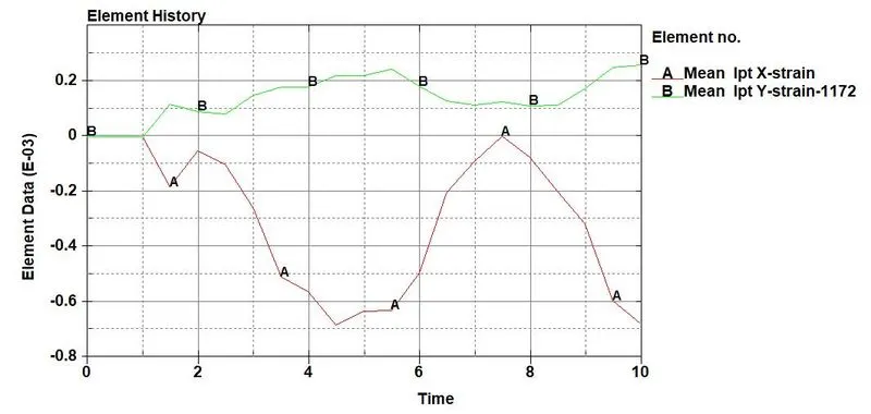
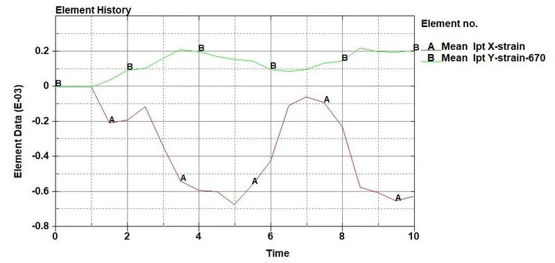
- To plot the strain value we need to insert a keyword file namely EXTENT_BINARY from the database. Also, padd the values from the History graph
Directional stress-strain(1P5mm)
Conclusion
The Crash box analysis Simulation is understood and performed with respected data furthermore plotted the deliverables graphs