Week 3- Challenge
OBJECTIVE
To create a simple bracket 2D drawing
To Mesh the Rear truss component
To extract the FE model
PROCEDURE
2D Drawing :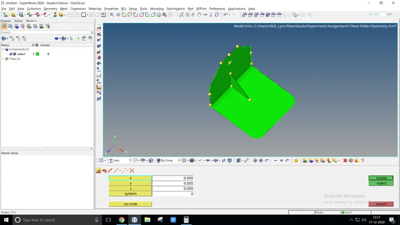
Create a node as required in the frontal view Diagram
Create an additional node, once created a node as an origin
Create an isometric positional node using the diagram and join the line accordingly 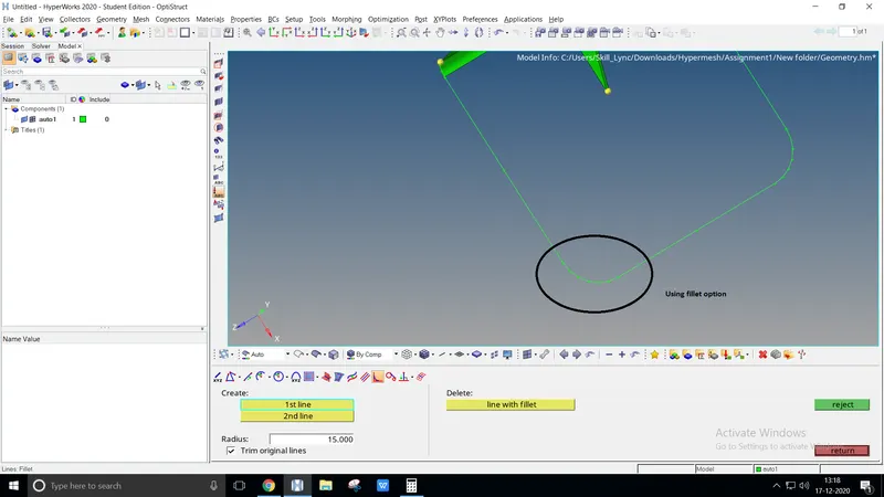
To create a radius at an edge, select lines > fillet
Select the required both lines and radius value as 15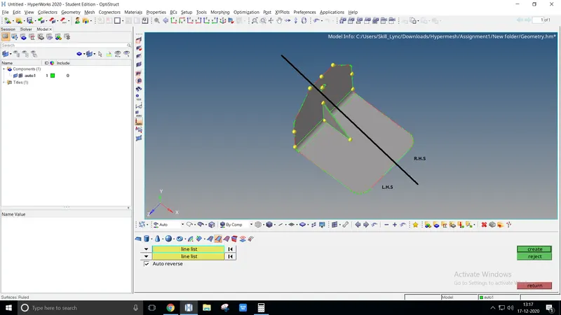
After creating a line, extend the line to the surface by surfaces > ruled
Select the line list equally both L.H.S = R.H.S and hit create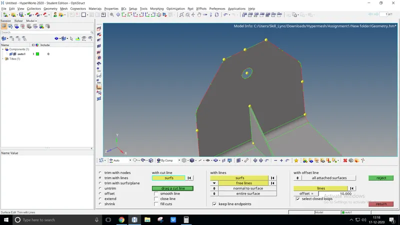
Create a Circle center and radius at the mid of the upper component by using node
Trim the circle surface, surfaces edit > trim with lines select the surface, free lines and select normal to surface 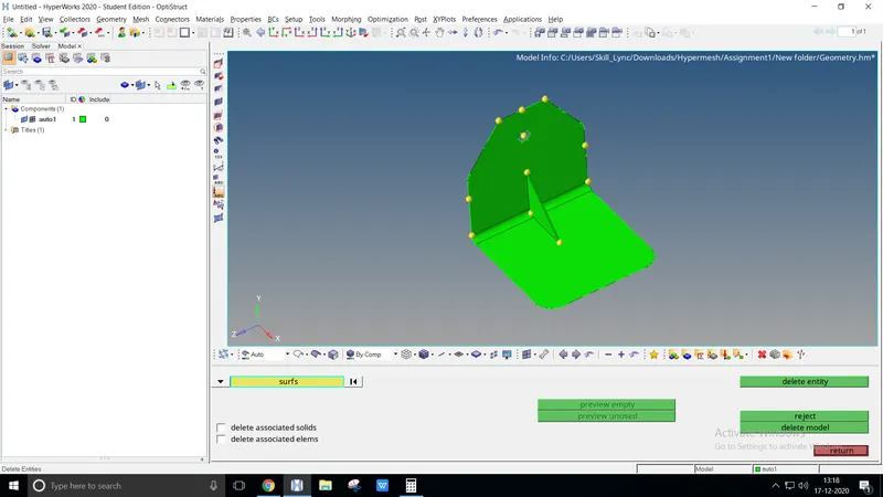
Eliminate the circle and unwanted surfaces by using the delete option as surfs 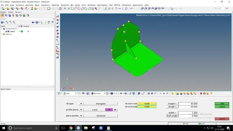
Lastly, select ribs profile plane as a z-axis
Rib start and end node is selected as temp nodes with required height and length value
The 2D meshing of Rear truss :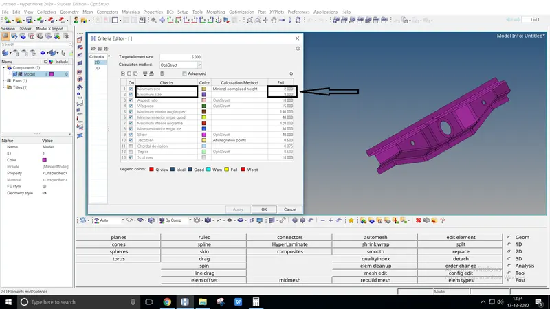
Set the element size as a minimum 2mm and maximum 8mm values as provided by Preferences > Criteria file settings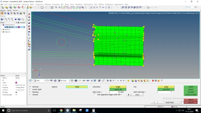
Determine one-half of the surfaces and start meshing properly, so that we can reflect easily
Clean and separate the geometry accurately before starting meshing. Start meshing at a target size of 5mm by each surface and smooth it
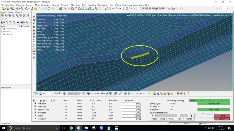
Using the Quality index option to check the failed elements and cleanup by elements optimize
Combine the trias mesh to another carefully by drag trias to form a quad mesh 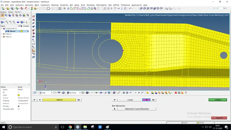
To reflect Tools > reflect select the elements as duplicate with a z-axis and select a base point common to reflect
The meshing component is undoubtedly reflected with an odd geometry further
Extract FE model :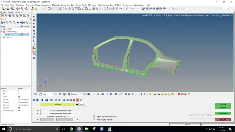
Select the mesh view as wireframe, to create surfaces > From FE select whole elements
Surfaces are created with an amount of element left
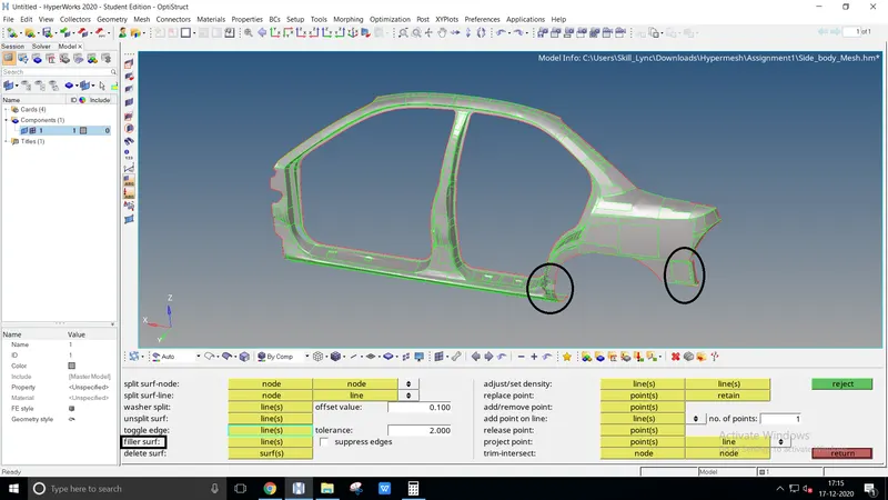
Using filler surf option we'd filled the surface using the line as mentioned above
CONCLUSION
The 2D geometry is designed
The 2D meshing is performed
The CAD surface is extracted
The above requirement is done using the given model