Interface analysis of Crash-tube and Meshing Bumper-assembly
OBJECTIVE:
Create the mesh for Bumper assembly, mesh size 6mm
Analysis of crash tube by varying cases and plot the result
PROCEDURE:
Bumper Assembly - The given model provides with a lot of constraints
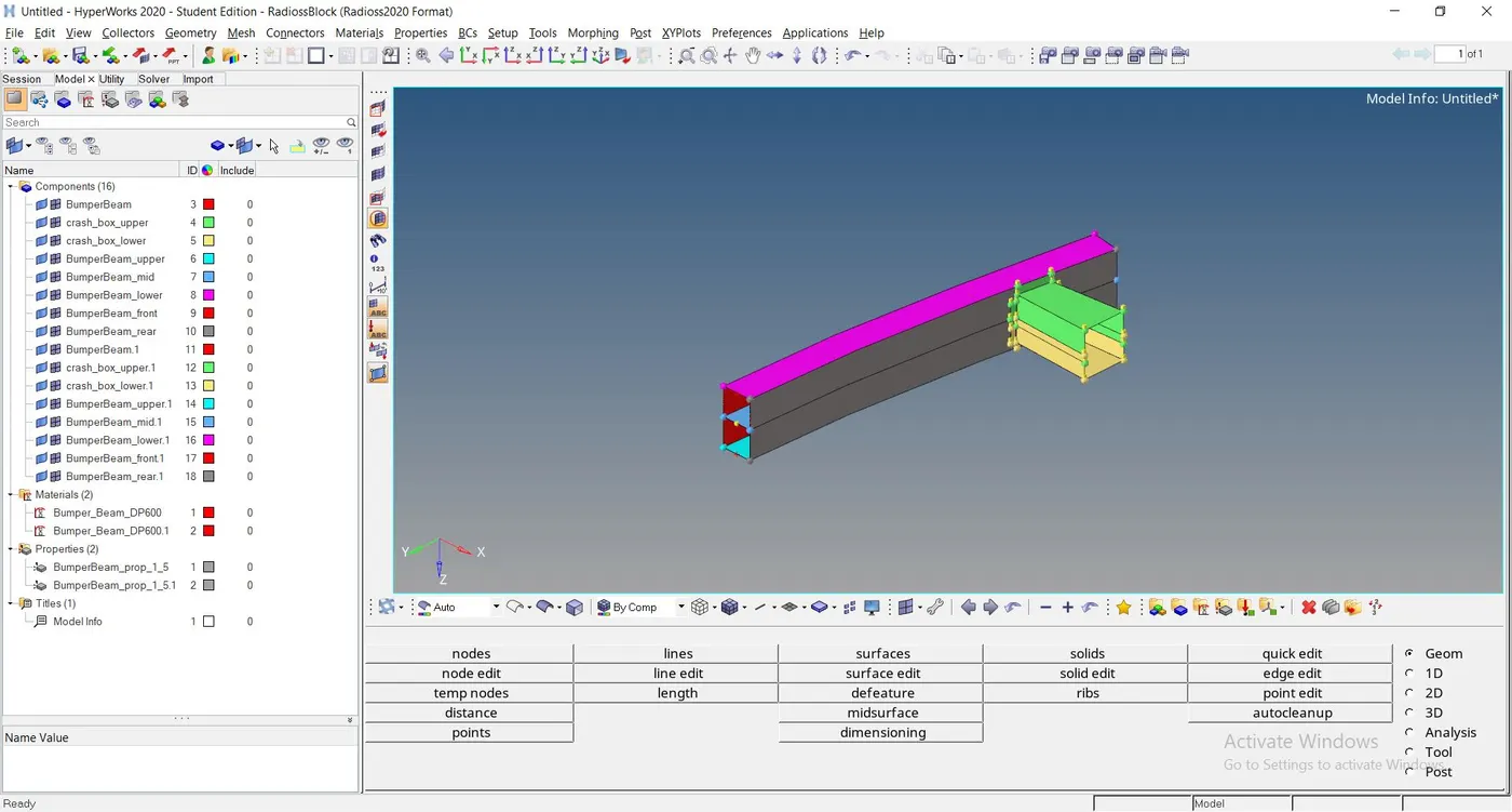
- Clear the free edges by aligning, trim & delete the surface components subsequently
- Clearing the surface components we could mesh it correctly
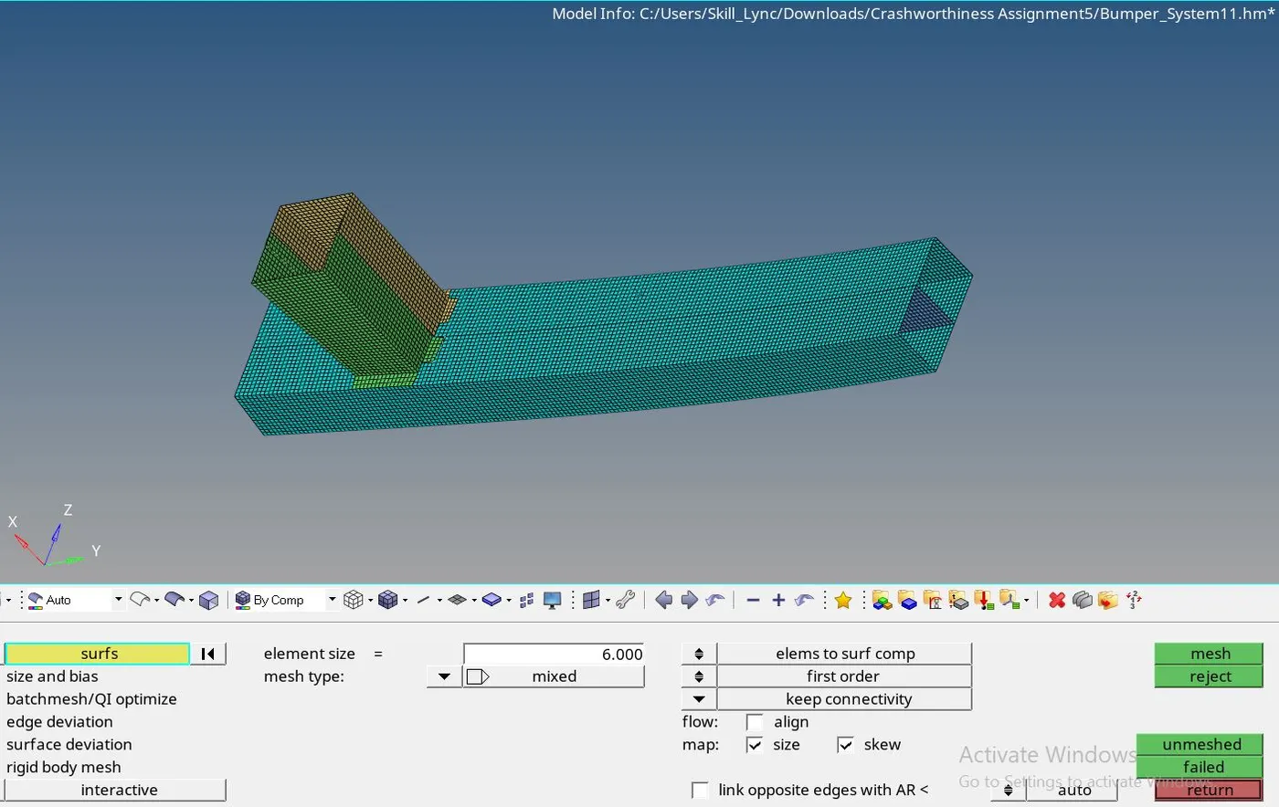
- Mesh the model by element size- 6mm
- Calculatingly align the nodes from the element components suitably
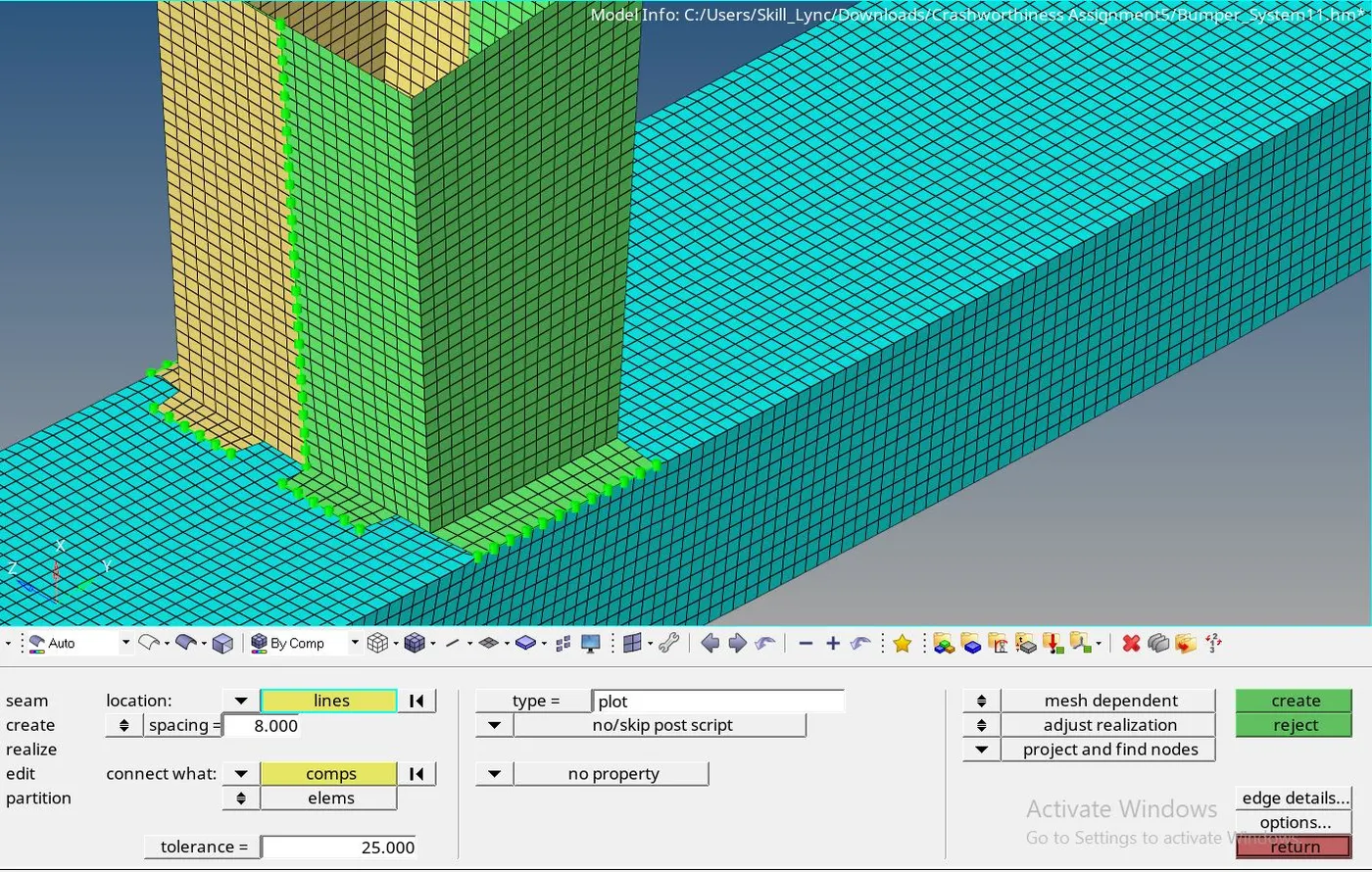
- After developing mesh, we could identify crash_box_upper and crash_box_lower components implemented some gap
- The seam welding process consolidates a gap as shown in the figure
Crash tube analysis -
Create an Output block as TH/PART and select all the components, run every case with the same parameters
The given model presents with contact interfaces Type 2 for seam weld, Type 7 for self contact
The penalty method is used on the interfaces, the initial properties are
| Istf | 4 |
| Igap | 0 |
| Idel | 0 |
| Gapmin | 1.0 |
| Inacti | 0 |
| Stmin | 1.0 |
| Iform | 2 |
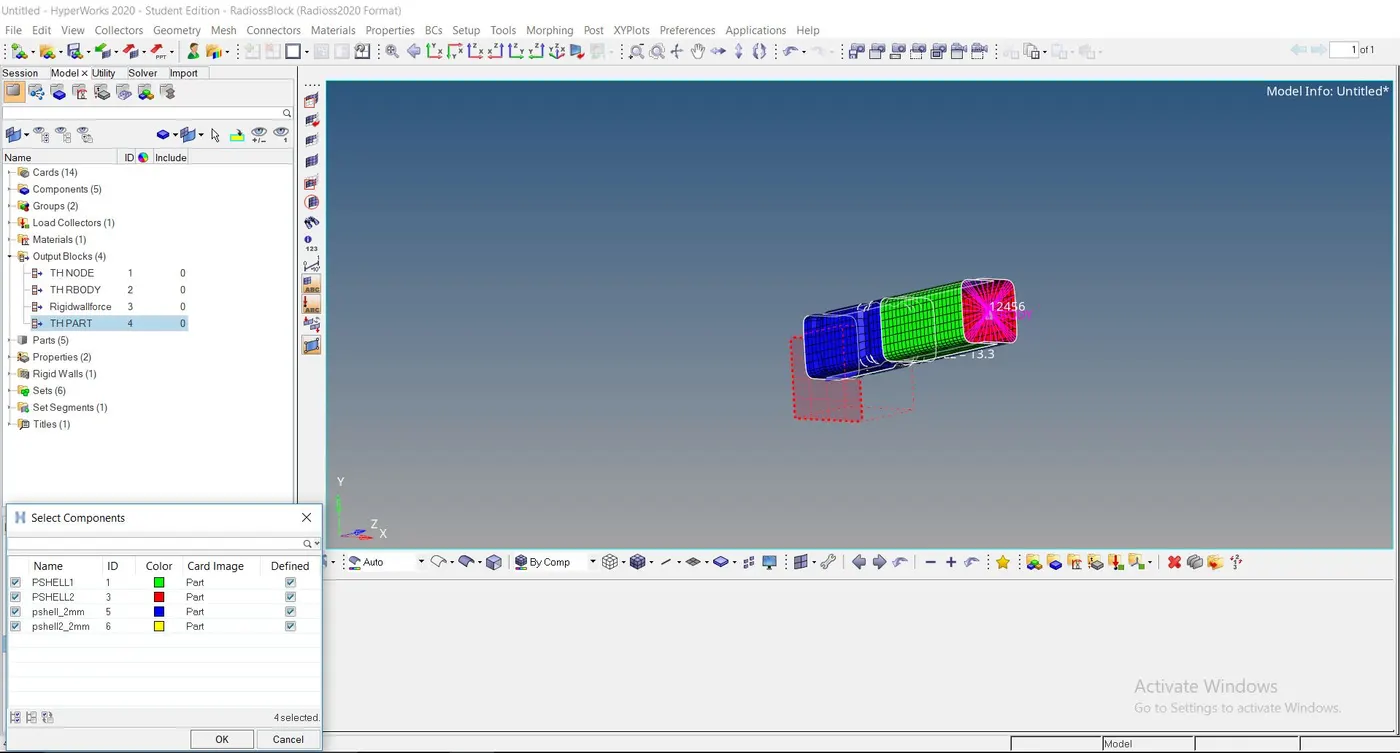
CASE 1 - Run the Crash tube model as it is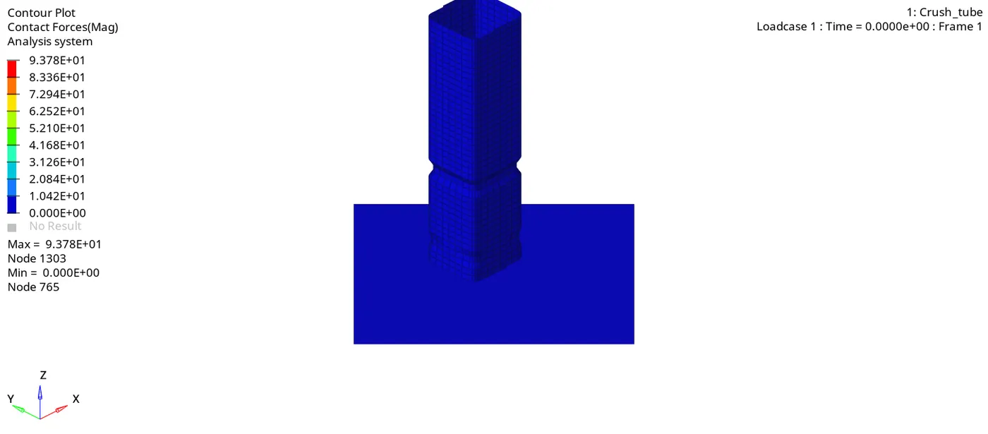
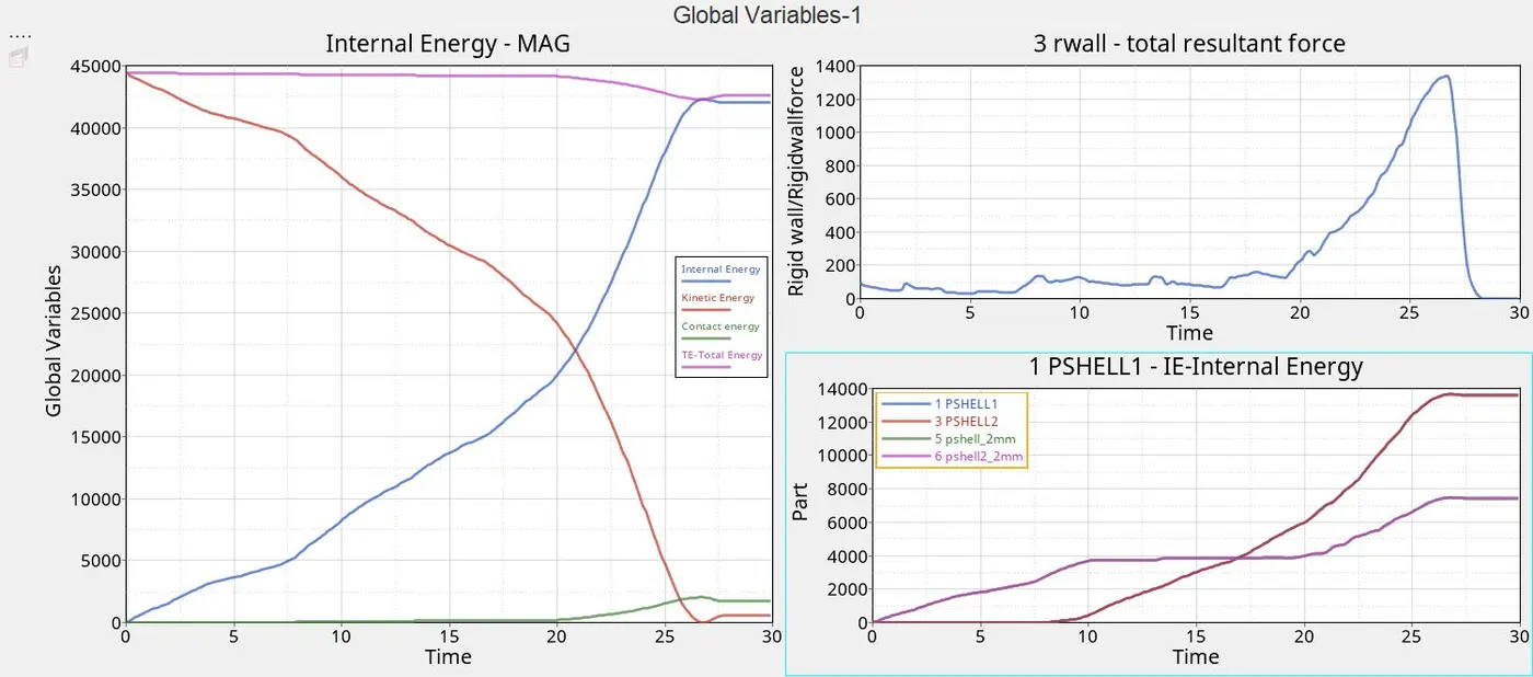
- The given model provided with TYPE 7 as self contact in which the slave nodes get contact with a master surface, it won't penetrate through the body
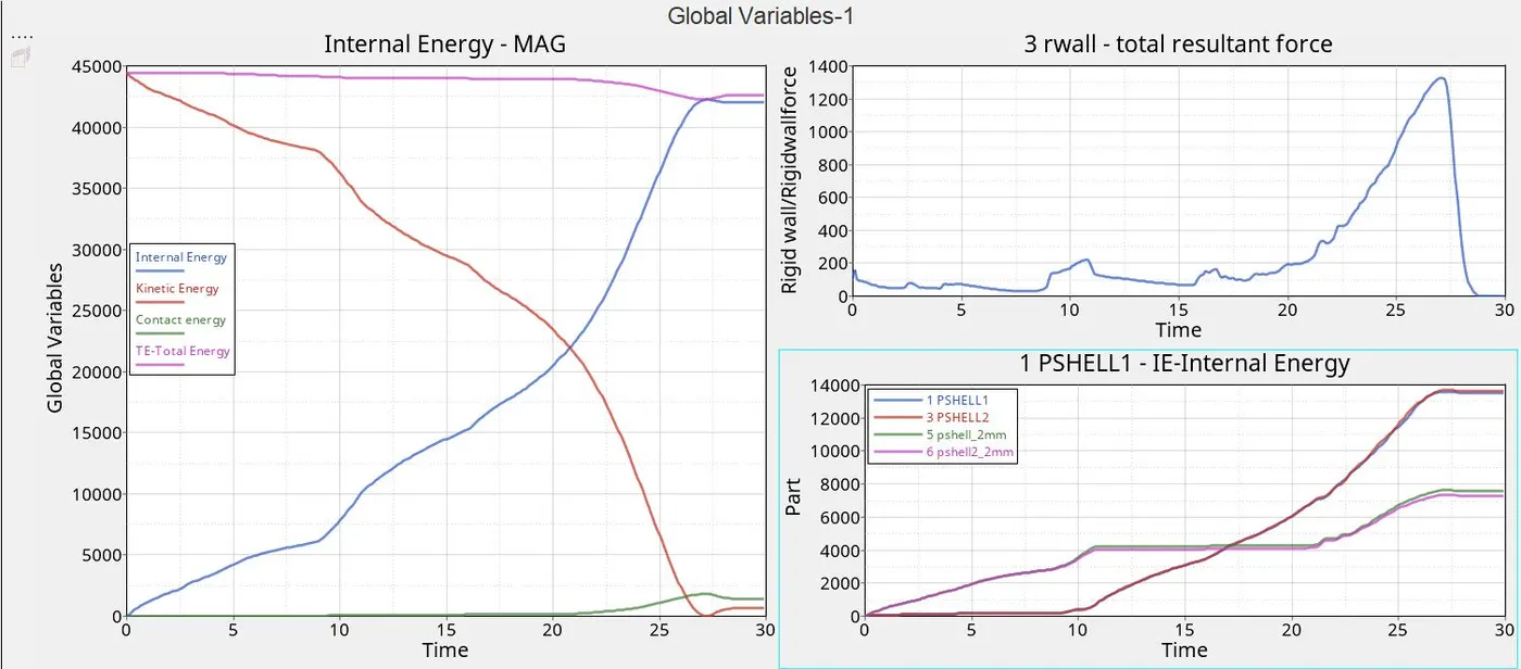
- Initial energies exposed here displays in order to the model, the internal energy gets higher accordingly to the second shell components rapidly also vice versa kinetic energy drops as the velocity get decreased
- Rigid wall force, contact energy refers to the same graph it shows the energy determined opposite resistive force
Mass error - 0.0
Energy Error - -3.8%
No. of cycles - 83496
Elapsed time - 156.16s
The negative error indicates the energy has been dissipated
CASE 2 - Change Inactive to 6 and run the model 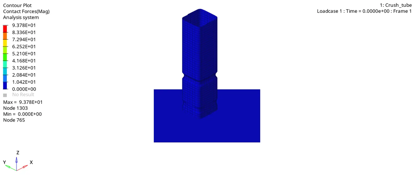
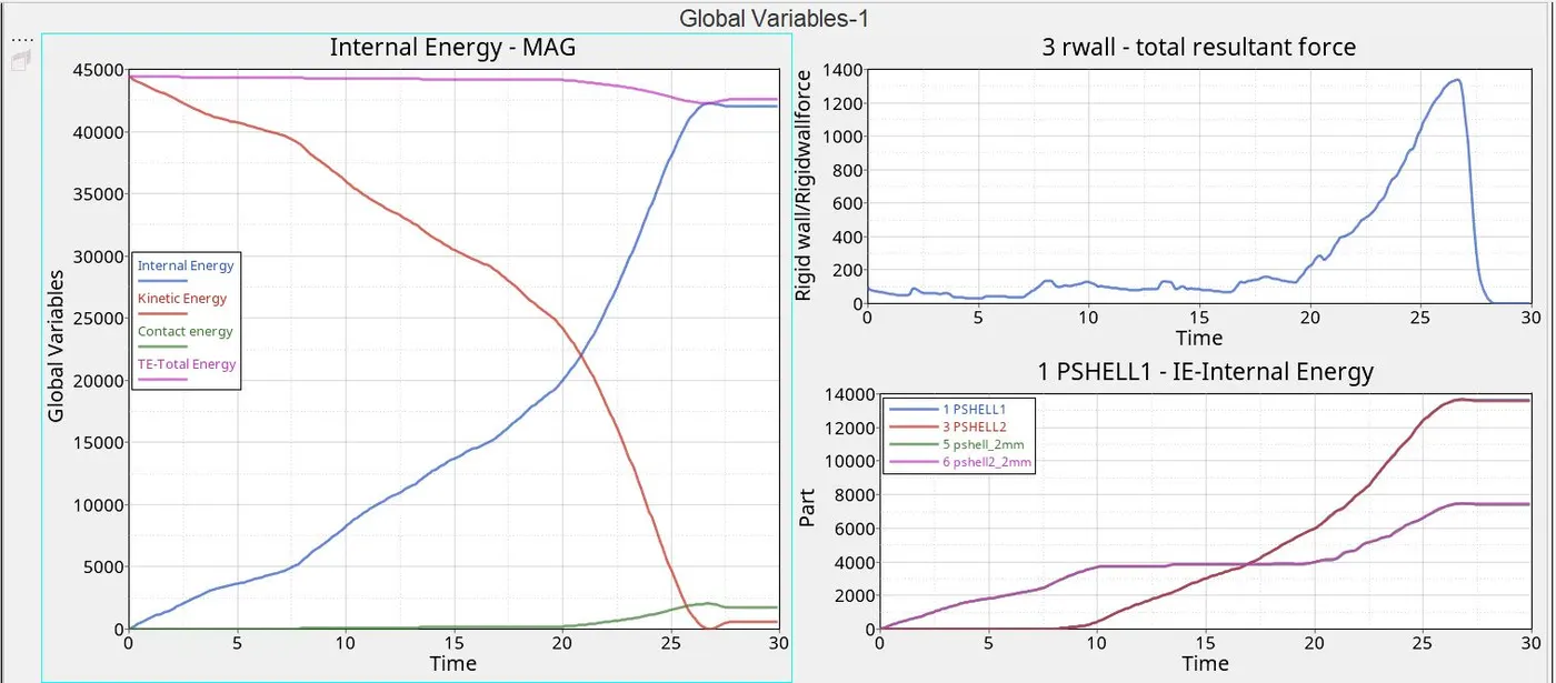
- The Inactive refers to the initial penetration process, the model doesn't possess any form of penetration initially
- The model performs as case 1, cause the default model also provided with no amount of penetration
- Similarly case1 = case2
Mass error - 0.0
Energy Error - -3.8%
No. of cycles - 83496
Elapsed time - 155.11s
The negative error indicates the energy has been dissipated
CASE 3 - Create/Change card image as type 11 and run the model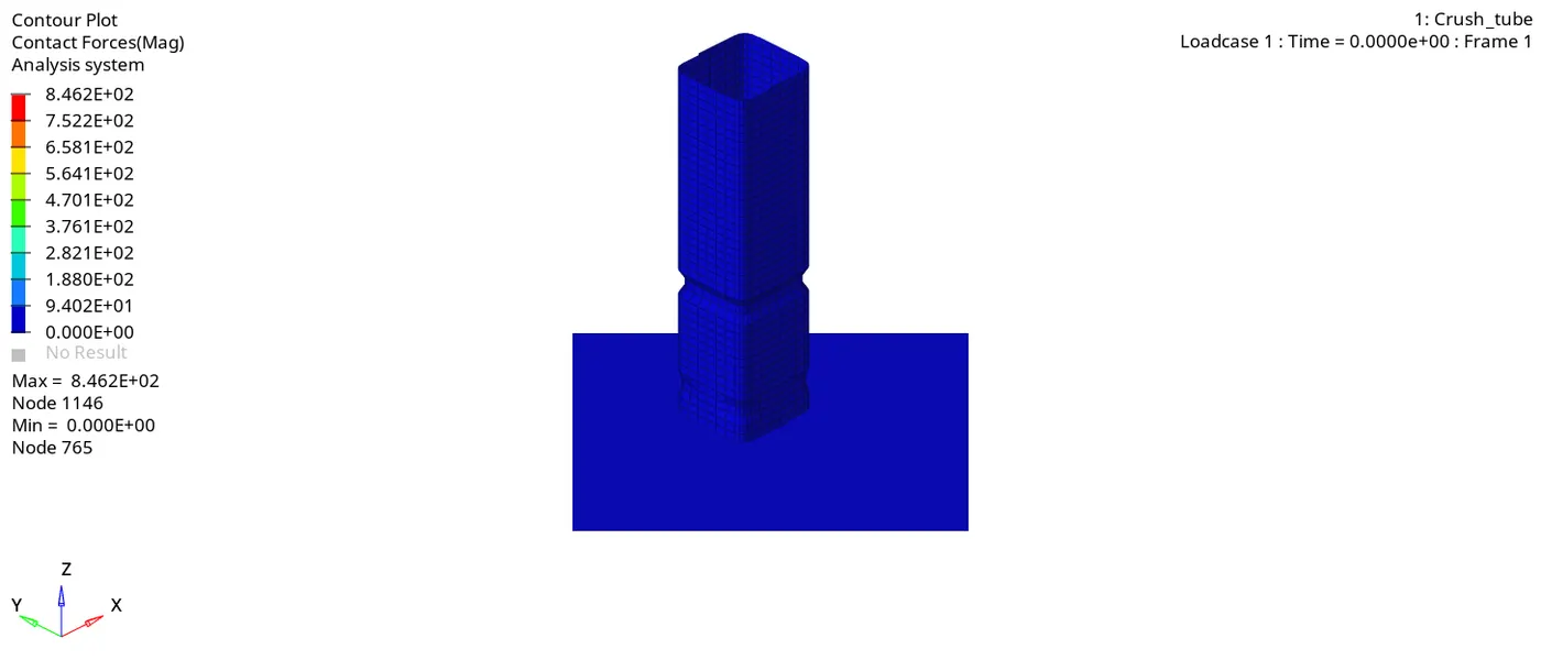
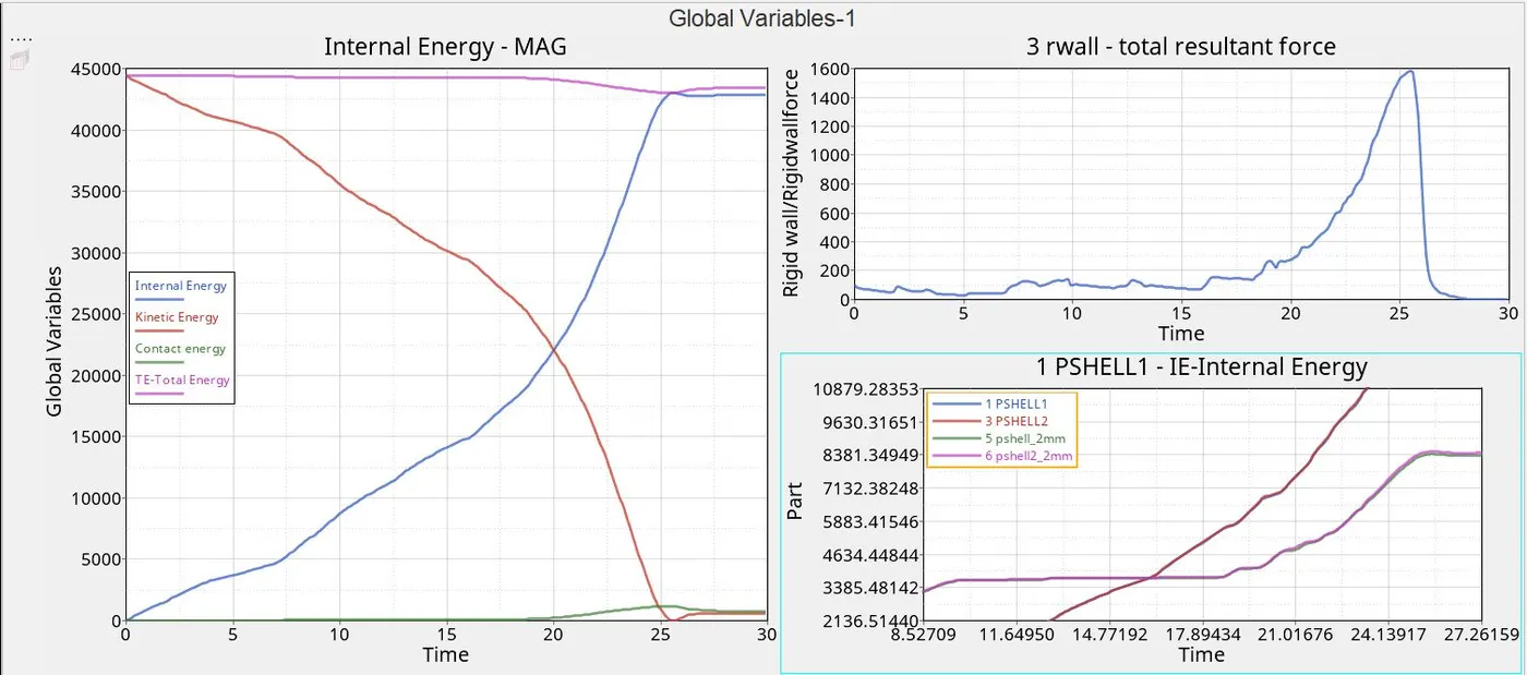
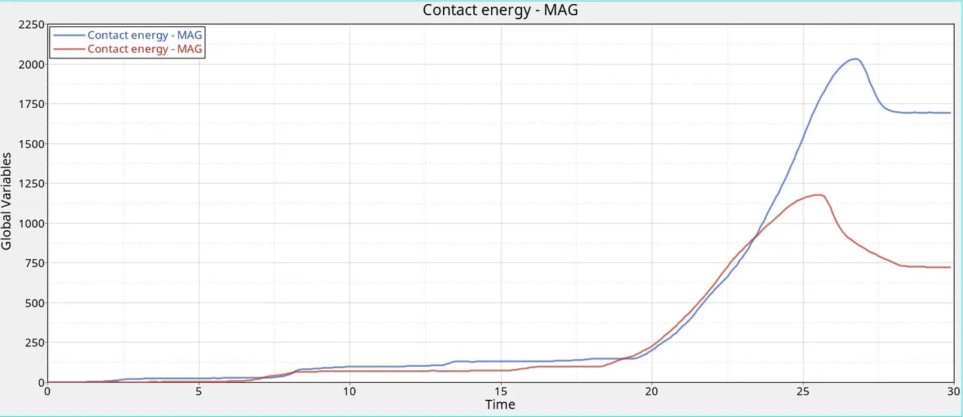
The above graph represents the type 7 and the type 11
- Constant energy decreases at the second graph i.e., type 11
- It has more joules value at the component and thus values become less compared to the type 7
Mass error - 0.0
Energy Error - -1.6%
No. of cycles - 130394
Elapsed time - 465.26s
The negative error indicates the energy has been dissipated
CASE 4 - Remove notches, boundary condition on the body and run the model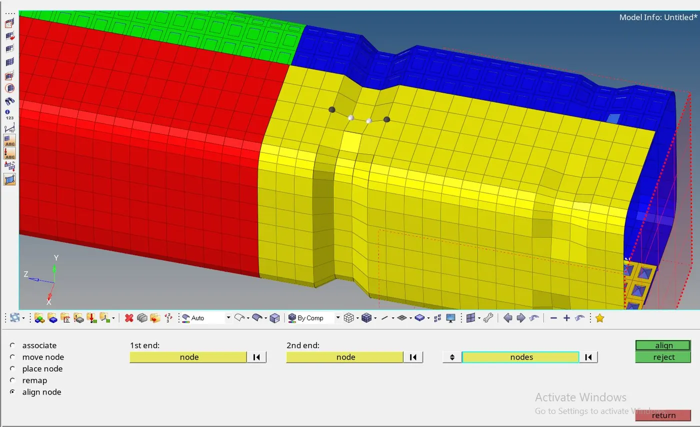
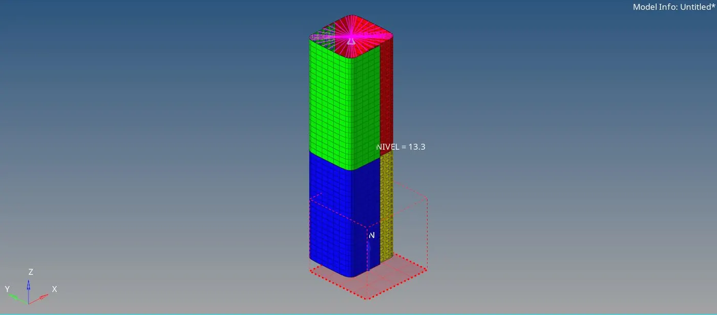
- Align the notches in the body node edit > align node > select 1st end, 2nd end and select the nodes to change
- Align the nodes systematically by order, the result is depicted in a figure
- Boundary condition removed by deselecting the Degrees of freedom from Solver > BCS > Entity editor
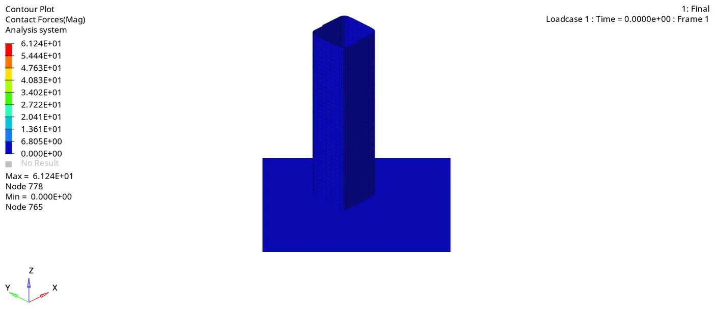
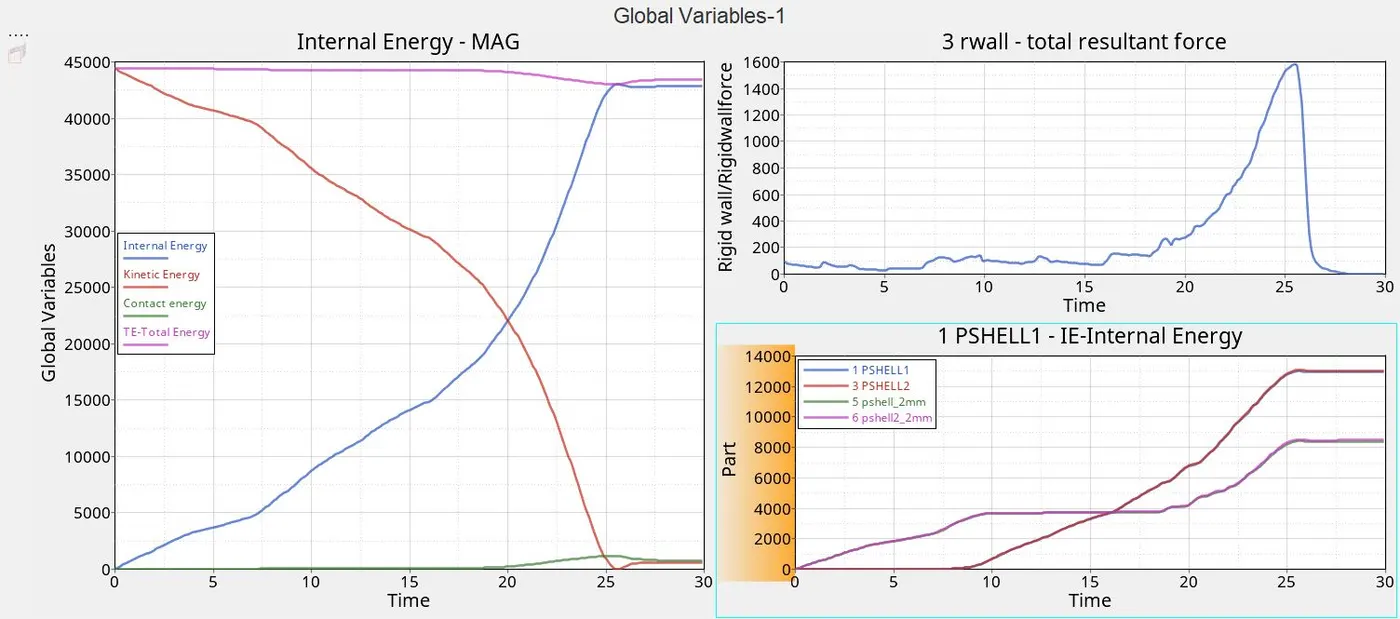
Mass error - 0.0
Energy Error - -3.0%
No. of cycles - 78444
Elapsed time - 140.43s
The negative error indicates the energy has been dissipated
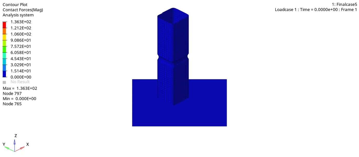
CASE 5 - Create a notch in the middle of the body and run the model 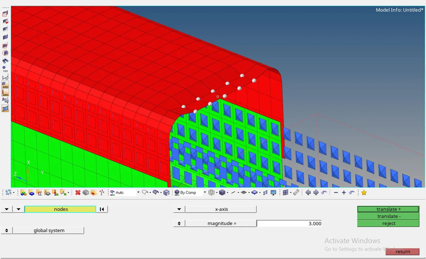
- Find the distance b/w the body and proceed a notch respectively
- To create a notch on the edge of the body use the three-node option, for the normal surface of the body use the axis
Mass error - 0.0
Energy Error - -3.2%
No. of cycles - 74053
Elapsed time - 130.99s
The negative error indicates the energy has been dissipated
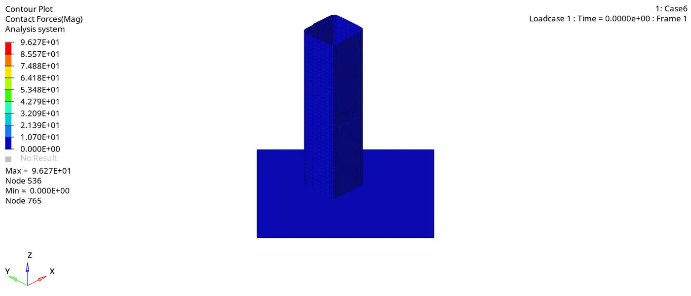
CASE 6 - Create a notch on opposite faces of the body and run the model 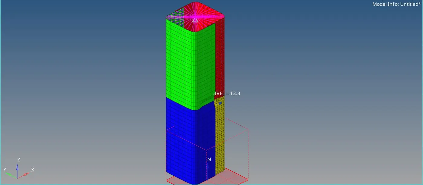
- The figure represents creating a notch anywhere by opposite faces of the body, run the default simulation
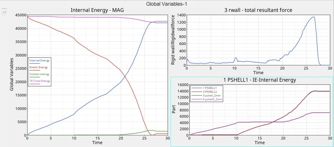
Mass error - 0.0
Energy Error - -3.5%
No. of cycles - 79943
Elapsed time - 139.87s
The negative error indicates the energy has been dissipated
From cases 4,5,6 global internal difference:
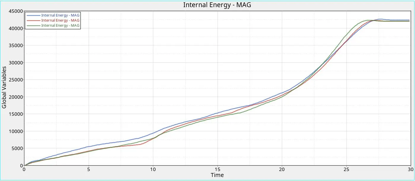
From the last three cases, the internal energy gets changes where the notch location get differs
- Case4 the internal energy performs rapidly because of the notch removal
- Case5 the internal energy performs and abrupts at the middle because of the notch
- Case6 the internal energy performs deliberately and attains peak because the amount of slave node pertains higher at the end
CONCLUSION
From the above,
The Bumper assembly meshed and provided the seam connector
The Crash tube analysis of six cases differentiate the form of energies by notch presence and parameters