Week 6 - Creating connection for Rear door
Aim:
- To create and implement the proper connections for the given meshed model (Rear door model)
Introduction:
- The way that some parts of an assembly are connected with each other can be a great factor of influence on the models’ behavior. For this reason, an optimization of the connection type or pattern offers an important improvement to specific model characteristics
- The different types of connectors such as Two Nodes RBE2, Cluster RBE2, RBE2-CBUSH-RBE2, RBE2-HEXA-RBE2, Nut and Bolt representation, Seam weld data representation
- The different types of operations such as Converting and Realizing operations, Connection manager operations, Assigning mass to a node
Procedure:
RBE2-Connections (Single Cluster)
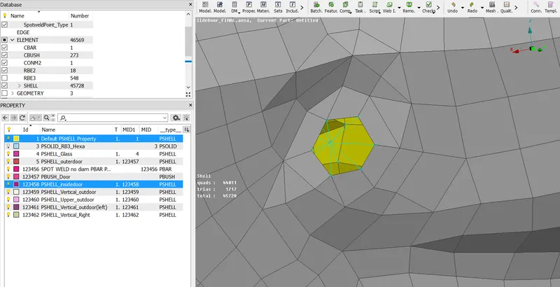
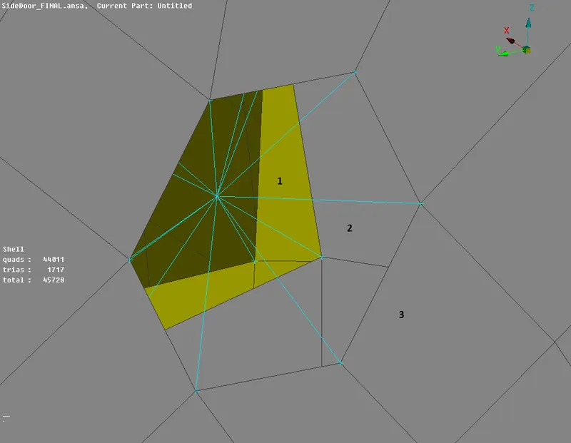
- In this type of RBE2, we provide connection to two or more holes on two or more surfaces which nearer to each other and lock their in all axes and all degree of freedom so that they can't move in any direction which makes them as rigid during the noise, vibration and harness simulation in NASTRAN, Elements > RBE2 option. We provide these types of connections wherever the two or more holes near to each other in the rear door model as shown in the figure given below
RBE2-Connections (Spider)
- In this type of RBE2, we provide a connection to one hole which is present on the model to make it rigid in all the axes which avoid movement during the noise, vibration, and harness simulation in NASTRAN
RBE2-Two Node Connections
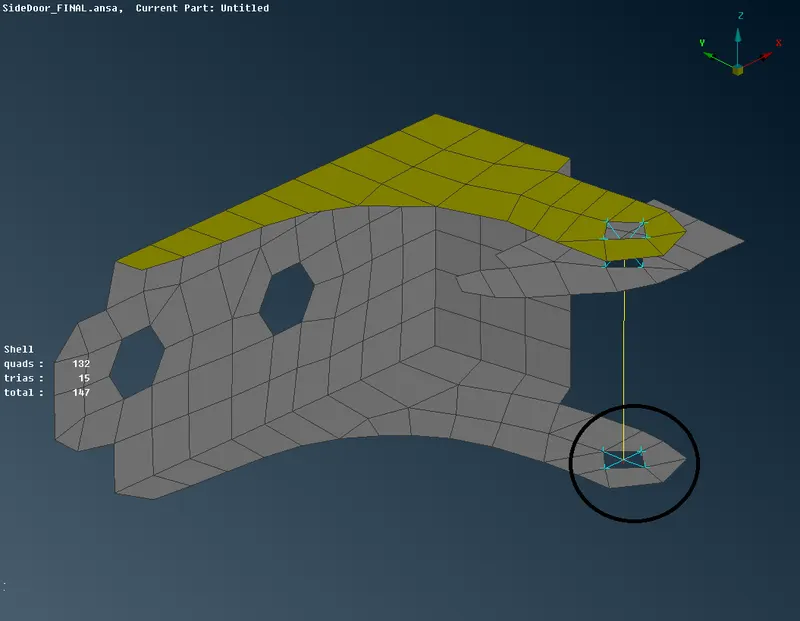
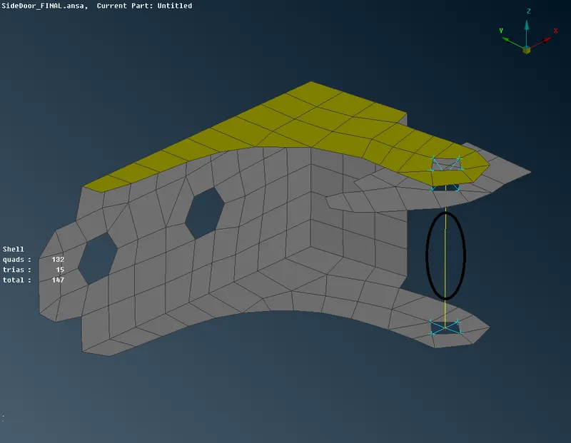
- In this type of RBE2, we provide connections in places like where the door hinges are present in this model. We should go to the NASTRAN module and under the elements tab we select the RBE2 option and under RBE2 we select the Two Node option then we select the two required nodes to create a connection as shown in the figure given below
- After that, we go to the elements tab and select the Info option. On selecting the info option, we select the two-node connection created and we get the information of the connection, in that we lock the degree of freedom i.e. CM to only 5 axes so the movement of the door can only occur in the 6 th axes i.e. the global Z axes during the simulation. The information tab is shown in the figure given below
RBE2-Connections for Door Handle
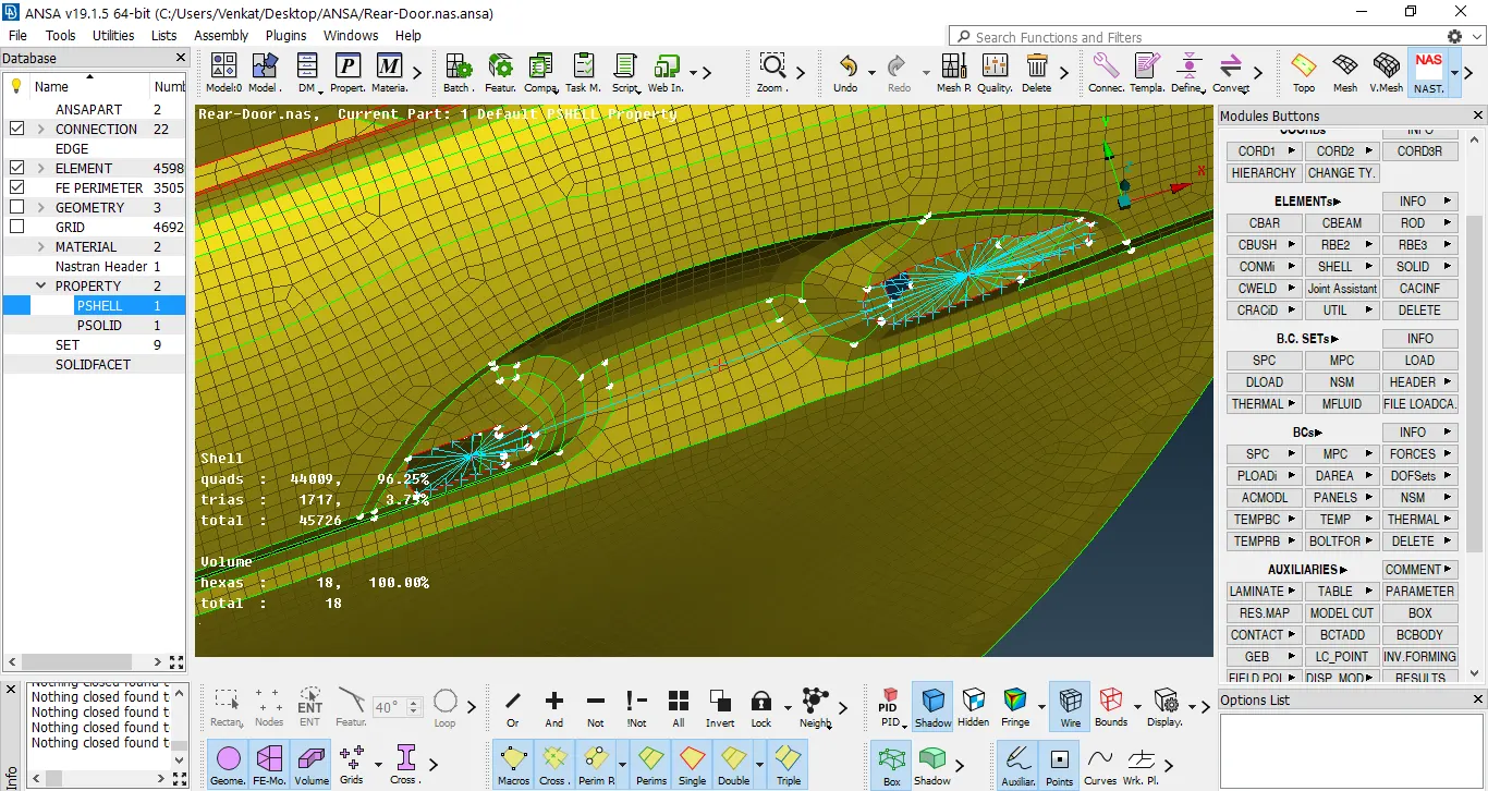
- In this type of RBE2, we provide connection in the door handle by providing the spider connections of two holes of the door handle and then connecting the two master nodes of the two spider connections to form a centroid or COG as shown in the figure given below
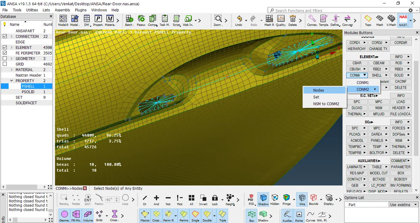
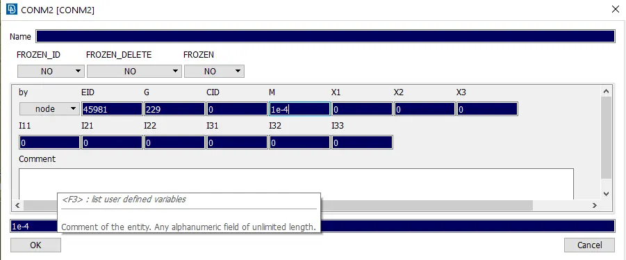
- Then we provide the Con mass for the COG point using the Nodes option present in the CONM2 in CONMi option in the elements tab of the NASTRAN module. Then in that tab, we provide the COG mass as 100gm
Spotweld-Connections (Weatherstrip)
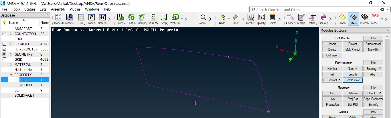
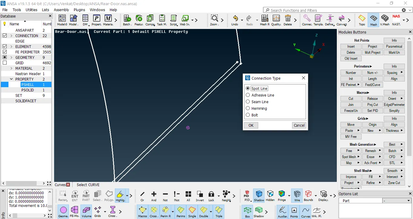
- In this type of connection First, we take the curves from the windows which include the fixed one near the C pillar and the sliding window or the main window using the Feat2Curve option present in the Perimeters tab of the Mesh Module. Then, we convert the formed curves into spot lines using the Convert option
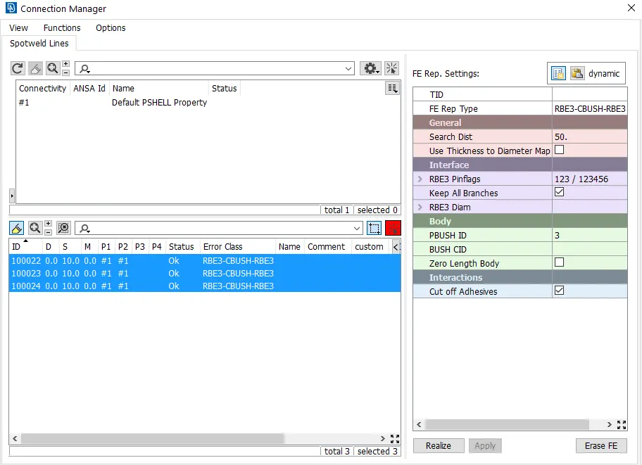
- We, then go to the connection manager to provide connect data. We have 3 tabs in the connection manager menu namely connectivity list, connection list, and FE representation settings. We go to the connection list and we proceed to give connection for which all parts we want using F1 tab we go to the model and we select each and every part and press enter to confirm since this model has a single PID we don't need to go every time and select the parts, after confirming the connectivity list tab is also updated based on the connections given
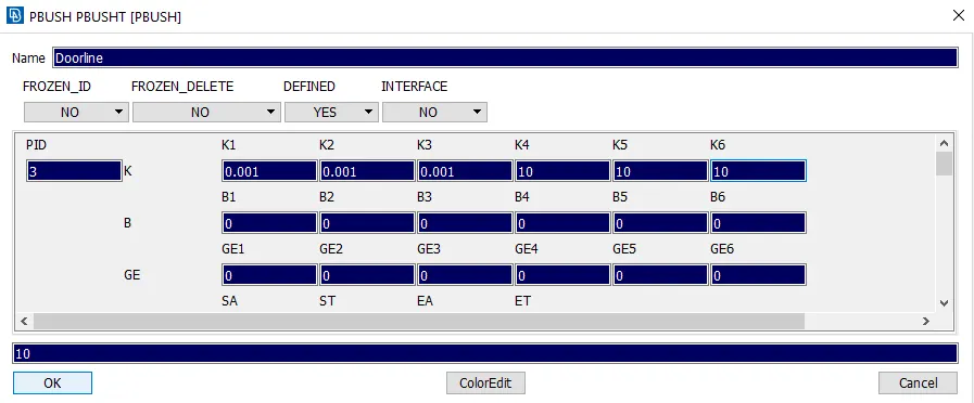
- We go to the FE Representation type and provide it as RBE3-CBUSH-RBE3. In that, we provide the search distance, we also tick in the check box of the Keep all branches so that we can visualize the spot line even after realizing it. We, then provide the Bush ID in which we provide the 6 different stiffness constant to the bush. Finally, we click on apply and realize. The figures of Bush ID and Connection Manager as given below
Correction (PBUSH)
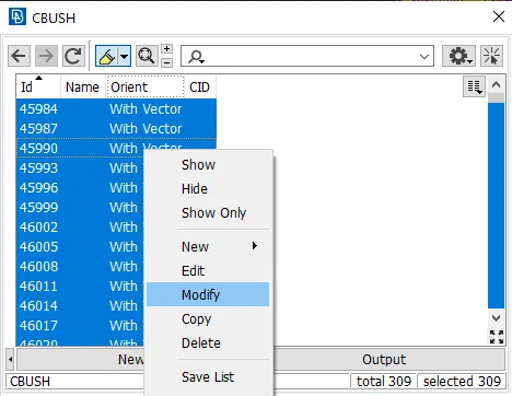
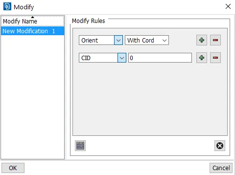
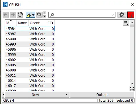
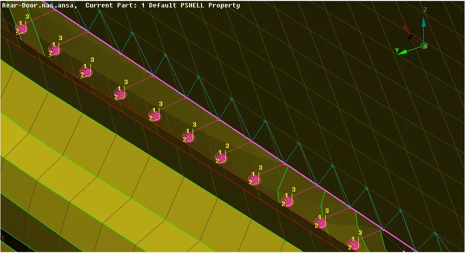
- After that, we go to the CBUSH elements and see that all the PBUSH elements are oriented with respect to the vector direction. Therefore, we change it with respect to the local coordinate system by right click on all the PBUSH elements and then give modify after a new tab opens and we go for new modification using modification rules where we provide orient as the modification and align it with respect to the coordinate, then give the coordinate point as 0 and then give ok. We obtain all PBUSH elements aligned in the same coordinate system according to the local coordinate system. The figures are given below
Conclusion:
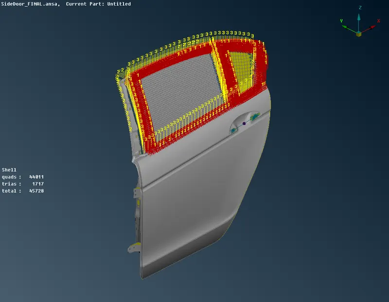
- We obtain connections for the whole rear door model which include RBE2 connections, Spotweld connections, and P-bush connections
- Hereby, I conclude that the connections for the given rear door FE model are implemented by applying the appropriate techniques