Side crash BIW
OBJECTIVE
To apply the given condition and plot the energy errors
PROCEDURE
Check unit system and either follow[Mg mm s] or [Kg mm ms] :
The given model is recommended with a Kg mm ms unit system. If not, change it in notepad without line spacing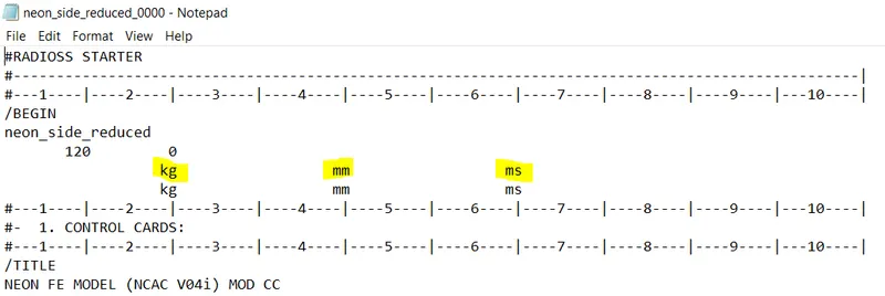
Create an appropriate interface, friction 0.2, and recommended parameters :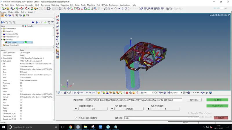
To create an appropriate interface, delete some existing group from the given model
Hide the rigid body to select the slave nodes & master segment from menu bar > browsers > hypermesh > mask - remove the rigid body
Create self contact by model > create > contact, select the card image as TYPE7, friction value as 0.2 and apply the following recommended properties as in applied units
Make sure of no penetration and intersections :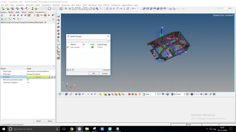
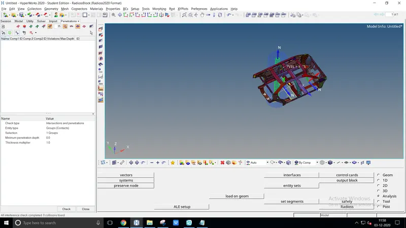
Penetration check is done by, tools(menu bar) > penetration check > select the group
0 collisions found would be defined as there are no penetration acts
Correct rigid bodies if any issue :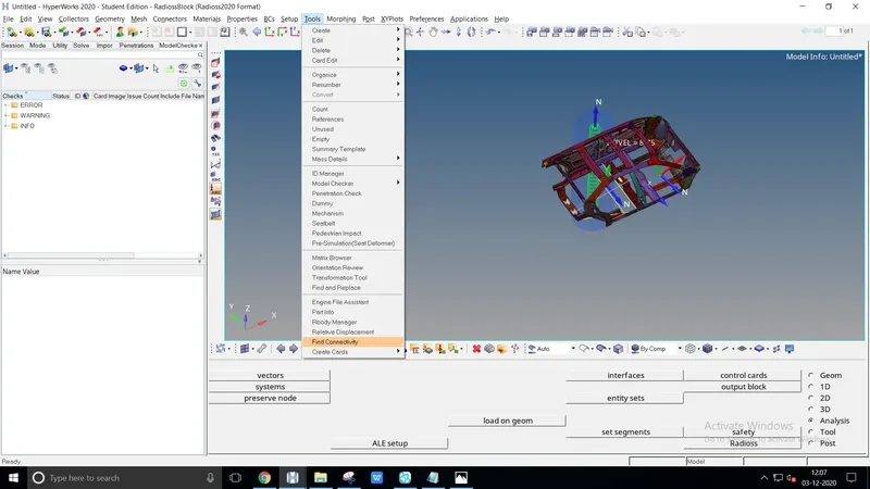
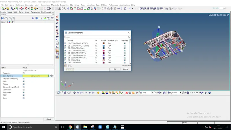
Rigid bodies could be solved by find connectivity, to unveils the parts which are not connected
Select the entire components and check for the free parts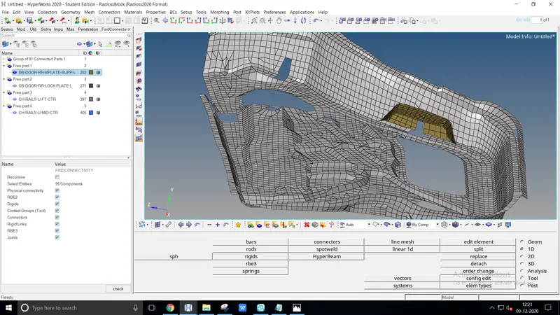
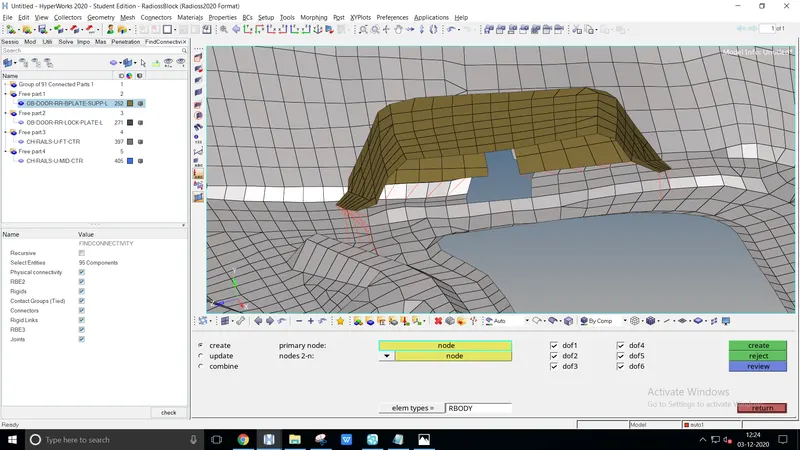
The free parts are connected by creating rigid bodies, 1D> rigids
Clear the entire free parts by constructing rigid bodies
Create a rigid wall with friction 0.1 as per the reference model :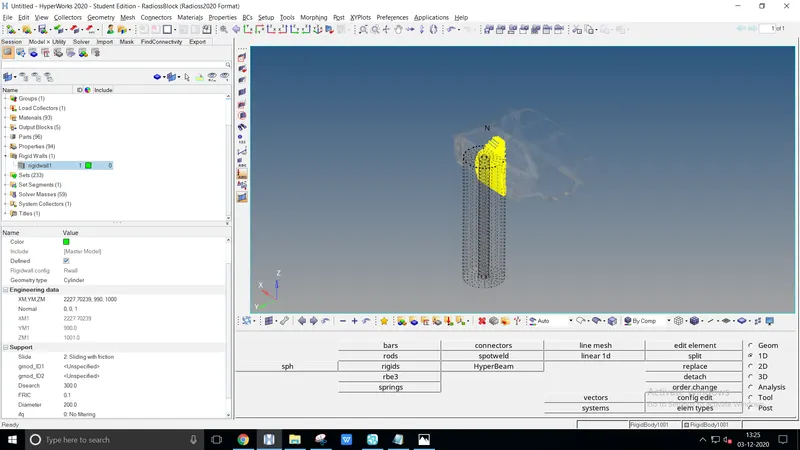
Create a rigid wall from the model, create > rigid wall
To apply friction value change the slide value as 2: Sliding with friction, FRIC - 0.2
Select the node from the engineering data, geometry as a cylindrical and normal force as a z-axis
Compare the model weight with the reference model and use added masses to reach the target weight of 700kg while getting CG about the required range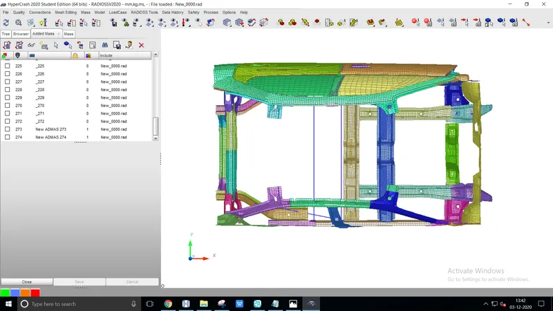
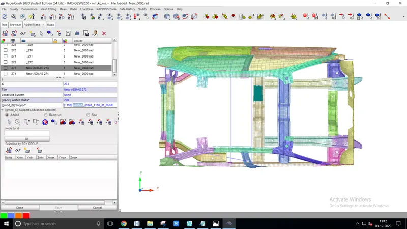
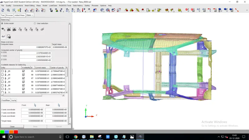
Export the model from hypermesh as solver deck, mass balancing could be easy at hypercrash
Check the COG virtually from the mass balancing and edit accordingly with an additional mass of succeeding 700kg
Create an entity as type=1 mass is distributed to each node of the node group, select the nodes and check the COG from mass balancing
Initial velocity as shown in the picture :
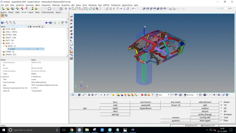
Velocity value differs with each crash test, for side crash test the velocity value referred to in nhtsa.gov as 31.5km/h
Convert the given value to required units km/h > m/s, 31.5km/h > 8.75m/s
Use model checker to ensure good quality :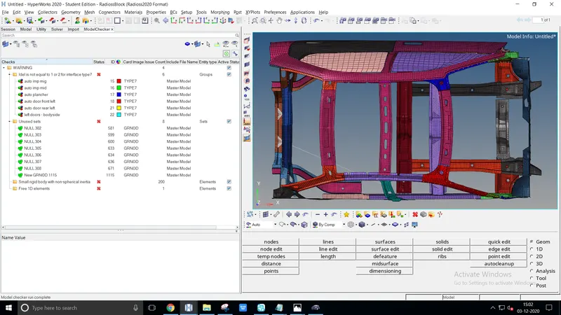
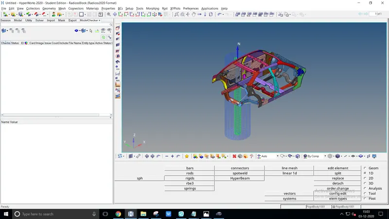
Open the model checker by, tools > model checker > radioss block. Run the model checker, list of warnings with subfiles will be displayed on the browser
Delete the entire warning files or run the autocorrect and check again until no other warnings displays
The model checker used to ensure the simulation process without any problem
Timestep 0.5 to 0.1 microseconds :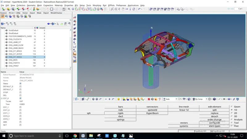
The given condition is converted to units kg, mm, ms
Convert the given value microseconds > milliseconds, we'll get 0.3 > 0.0003
Open model > cards > ENG_DT_NODA > change the Tmin value as converted value i.e., 0.0003
Sectional force in the cross member :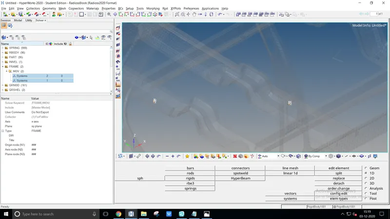
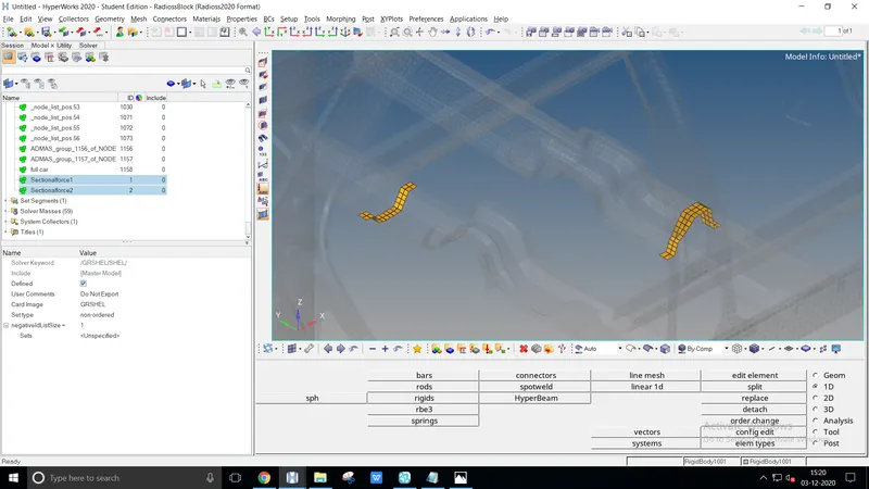
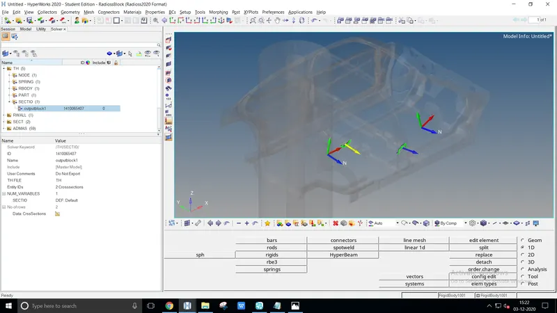
To create a sectional plane solver > create > frame > MOV an entity browser will open
Select the node N1, N2, N3 axis accordingly perpendicular to depending on Z-axis, parallel to the rigid wall
Create a set of elements representing the local frame entirely vertical, Open model > create > set to select the element's ID
Again solver > sect > sect, enter the existing nodes created, frame_ID, and grshell_id for identifying the sectional part. Create a time history step solver > th > sect and select the entity_ID
The intrusion at B pillar, hinge pillar, and fuel tank region :
The intrusion can be defined by the spring method and skew method
The spring method provides a defined value with the amount length. The mass and stiffness of the spring diverse the displacement movement
Whereas the skew method provides a precise value without changes in the deformation such as in stiffness method calculation. Length couldn't be measured
Spring method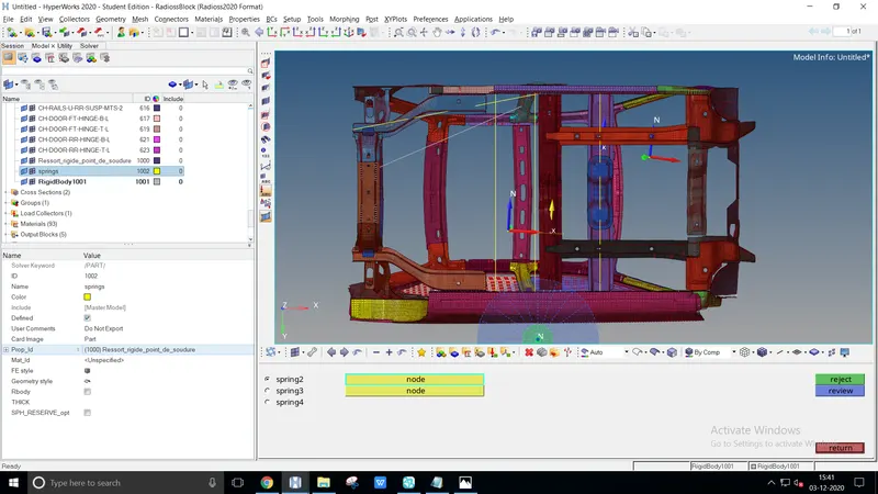
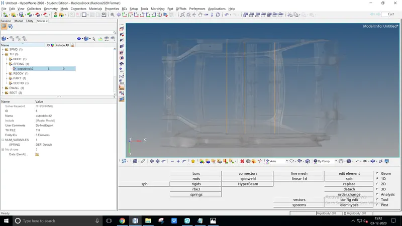
The spring method is used here for a convenience
Create a spring, 1D > springs > select the two edges of the node
Create a time history part, TH > spring select the spring from the entity ID
Skew method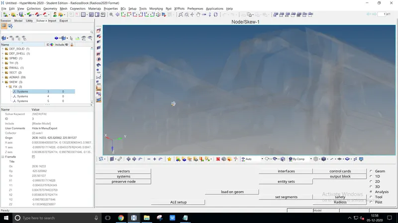
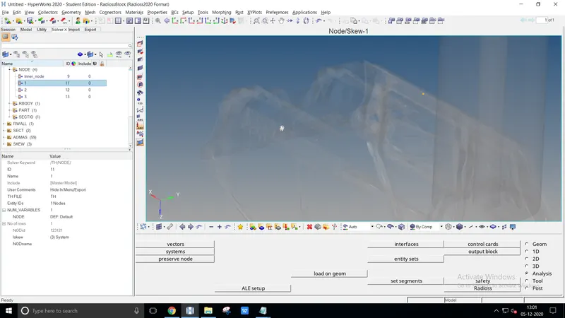
The skew method is used as a general before
Create a skew, Create > skew > fix select the node alignment properly
Create a time history file, Create > Th > Node select the entity ID and required Iskew
Peak velocity of the inner node of the door :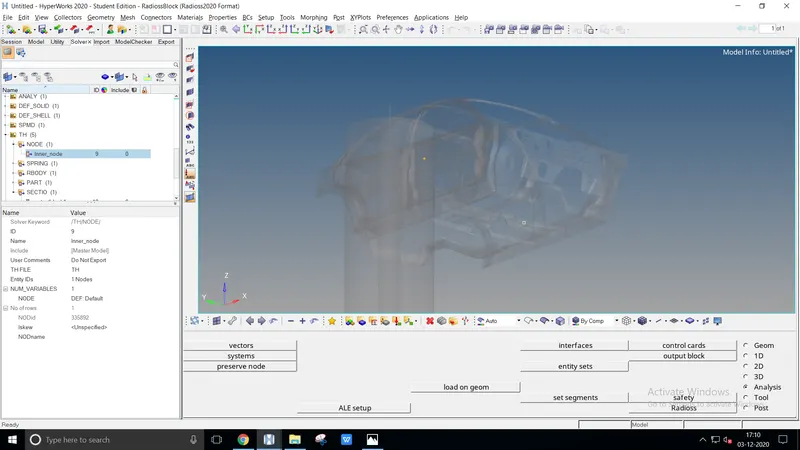
As mentioned in the video select the inner node to get a peak velocity value
Create an inner node by th > node, select the entity ID directly
INFERENCE :
Simulation file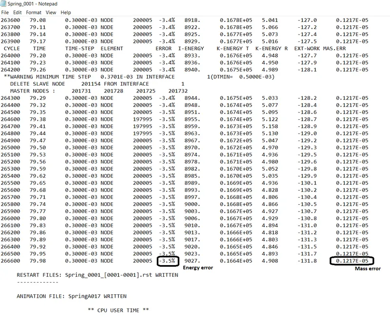
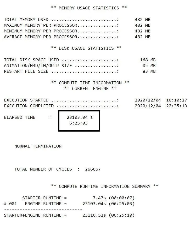
Check the simulation process by ensuring the data cards, given condition and save it at the properly defined folder
The simulation energy error should be below -5.0% for better results. The determined spring model values are energy error -3.5%, mass error 0.1217E-05
Hypergraph
Two cross member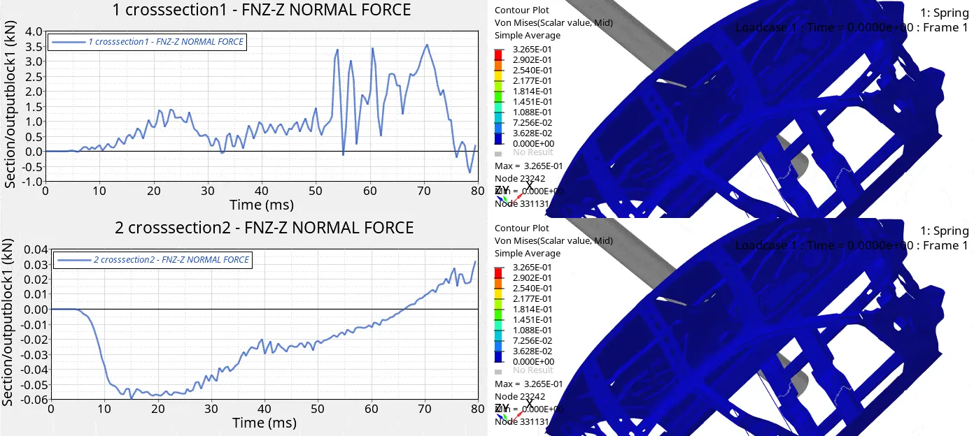
The force acting on the first, second membrane is 3.6kN & 0.03076kN at max
The maximum stress peaks up to 3.265E-01N/m2 at the node of 23242
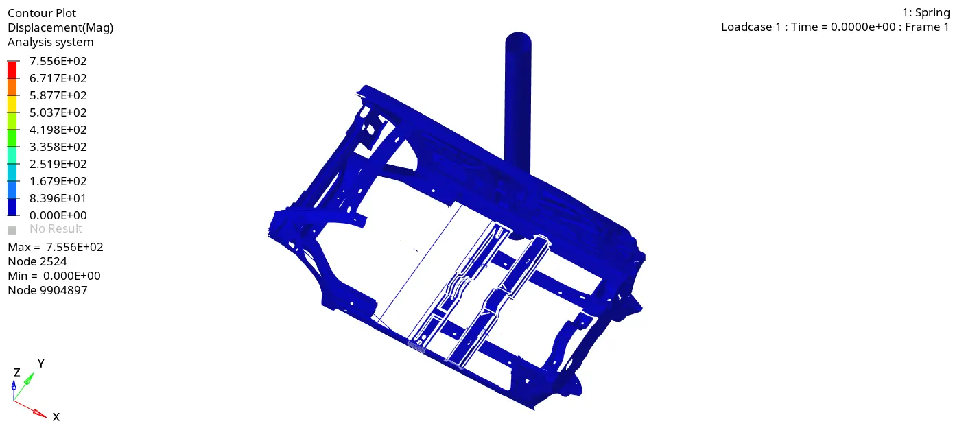
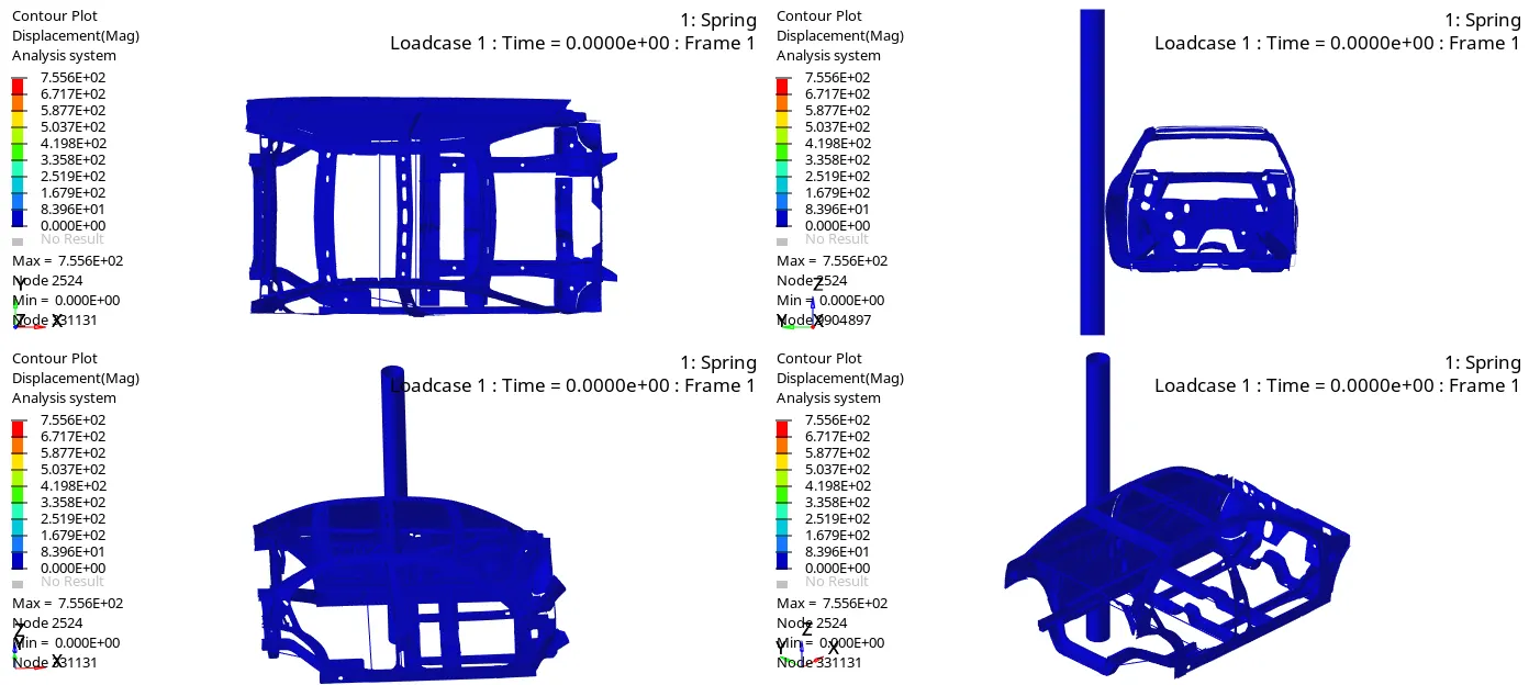
The above gif file differs the displacement b/w two member
Intrusion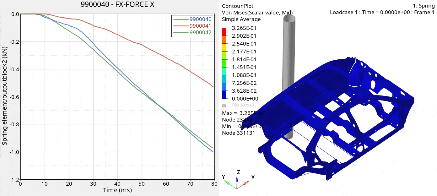
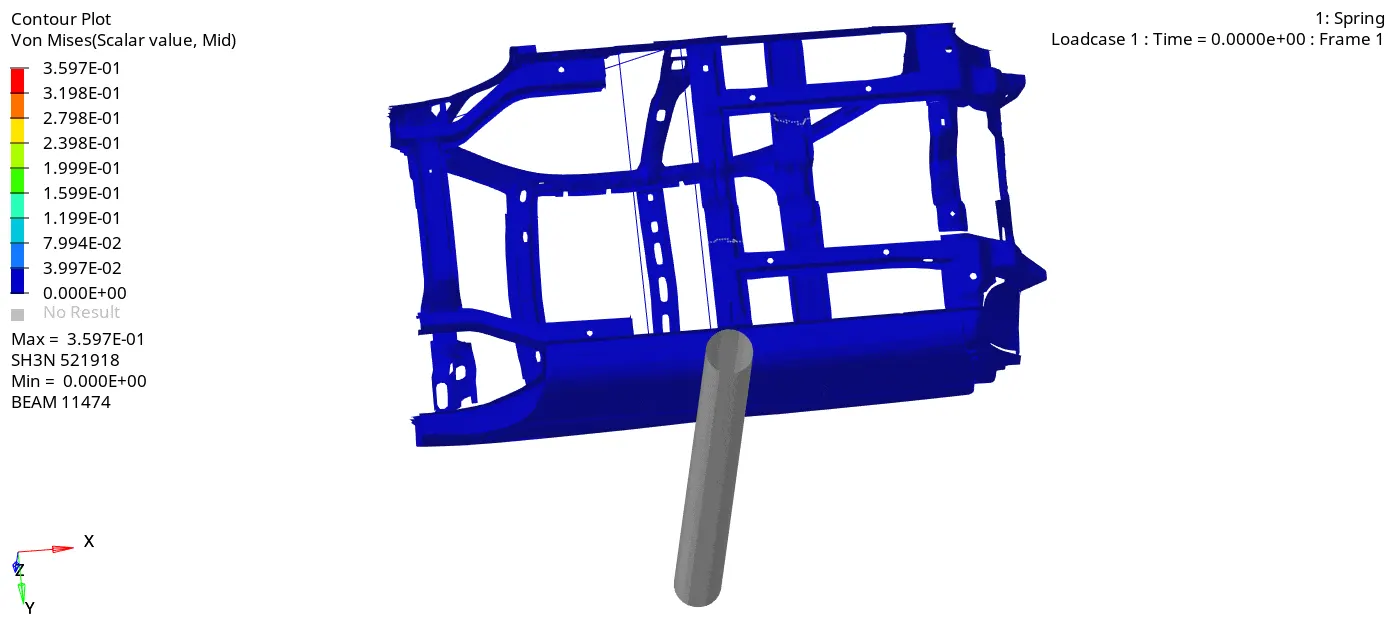
The three intrusions are denoted using the spring method to defined the forces
The maximum force attain on the B pillar, Hinge pillar, and fuel tank region is listed on the graph orderly
Recommendation for reduction of Fuel tank region
- Providing stiffeners in the region, adding strength or change of materials
- Adding stiffness to the frame such as Flanging, Hemming, Emboss, Ribs
- Process parameters are important to avoid tear, which may compromise durability
- When all the above feature additions fail to provide you with the required rigidity it's better to add extra brackets, plates for stiffness
Inner node 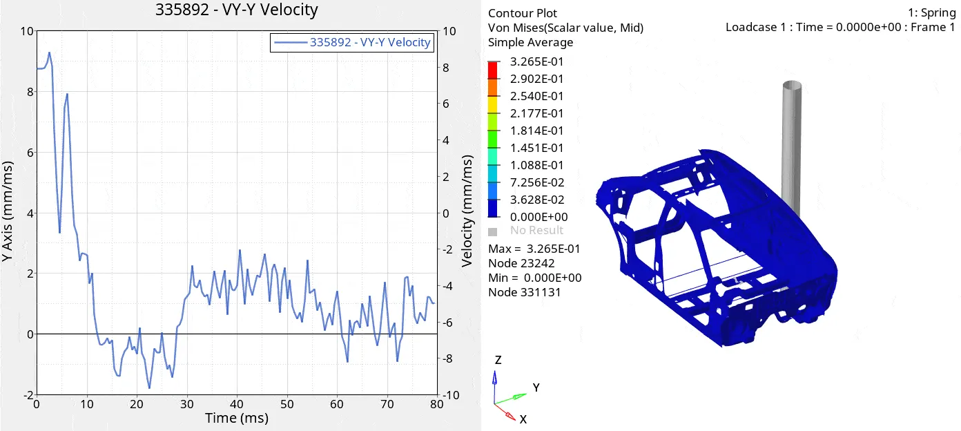
Peak velocity of 9.30264mm/ms is initiated at the node 335892
The gif file represents the inner node velocity as a red thin layer on the front door
Energy plot - Global variables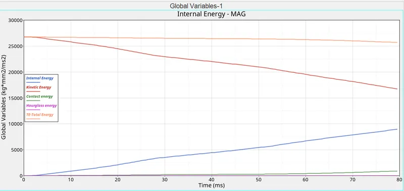
The global variables determine the internal energy is absorbed during the impact of the rigid wall up to 8970 Joules
The kinetic energy gets dropped by virtue of a motion passes through the wall by 16755 Joules
The contact energy is less comparatively because of the low velocity up to 907 Joules
The hourglass energy always low and inversely proportional to Total energy
CONCLUSION
The errors are plotted according to each inquisition
From the above cases, the energy error didn't exceed the critical scale