Roof crash BIW
OBJECTIVE
To apply the given condition and plot the energy errors
PROCEDURE
Import: Car, Impactor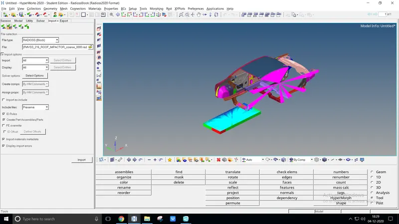
Transforms - Rotations: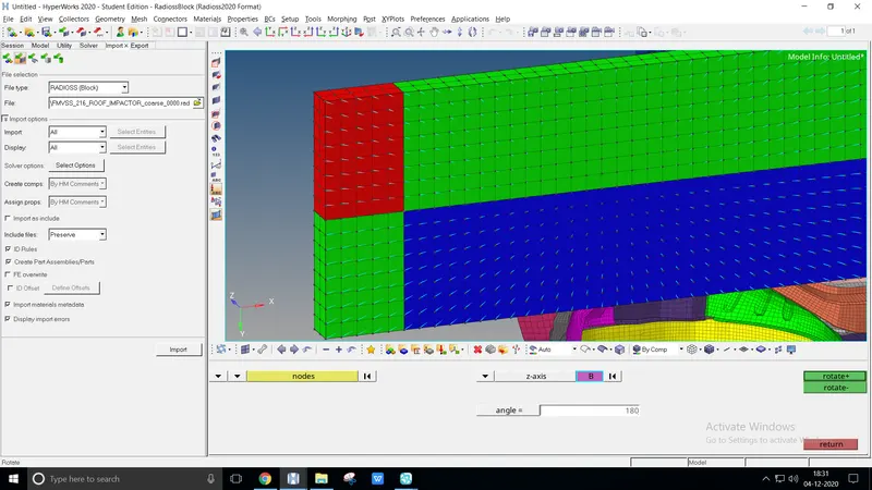
Rotate a given impact on the following axis condition
Open Tool > Rotate, select the following nodes (Impactor), global axis, base point, and enter the angle
Transforms - Translations: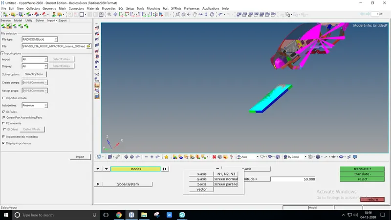
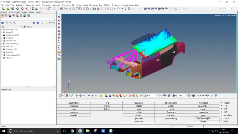
Translate a rotated model to the proper alignment under given conditions
Open Tool > Translate, again select the following nodes (Impactor), global axis and enter the magnitude value orderly
Interfaces: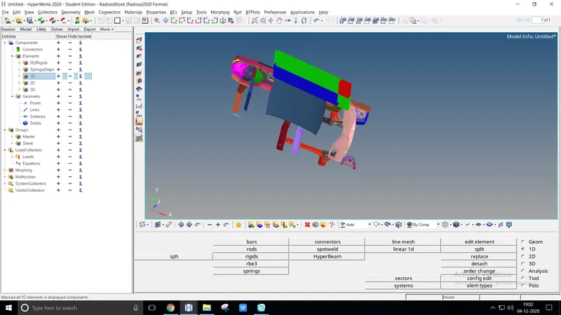
To create self contact between Car and Impactor, mask all the Rigid body, Springs, and 1D elements
To mask the entire 1D elements by, View > Browsers > Hypermesh >Mask. Hit the negative sign to mask the elements
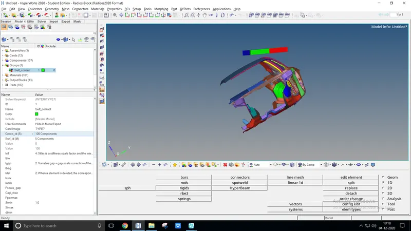
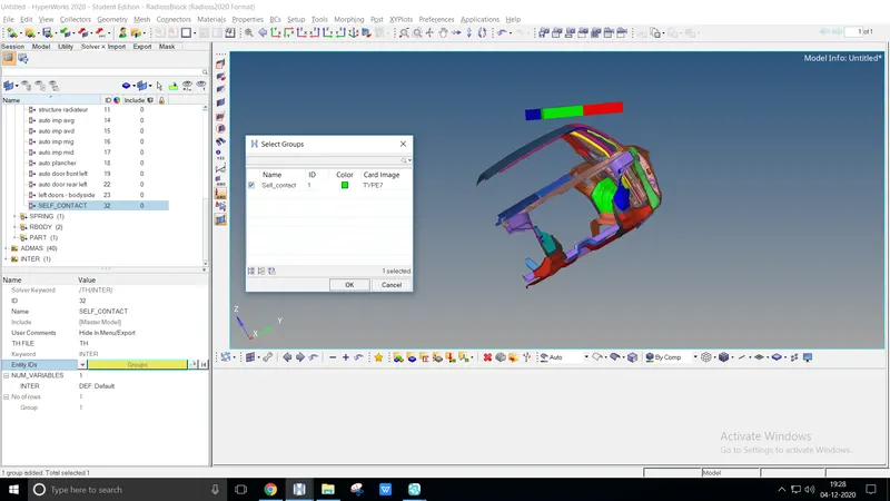
Create self contact as TYPE7, select the following recommended parameters, create a Slave node, and Master segment components
To get the displacement value from the crash test, create a time history file TH > Inter select the Entity ID
Boundary conditions :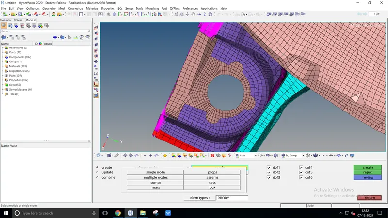
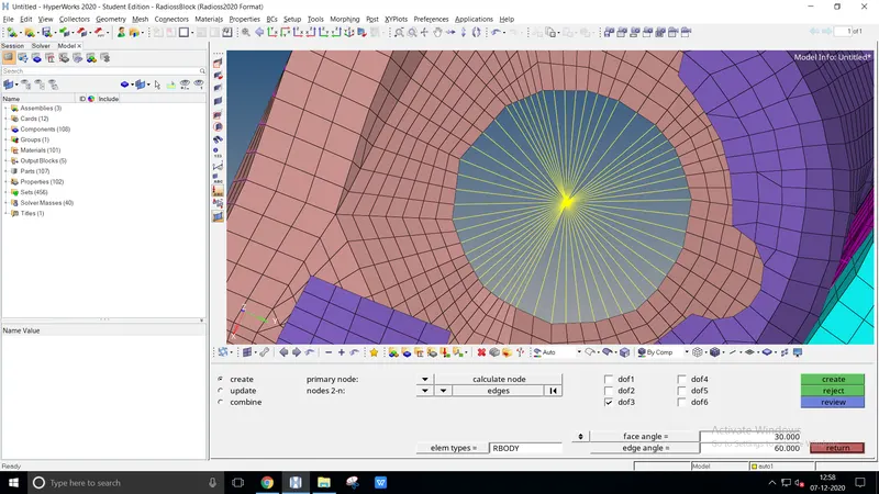
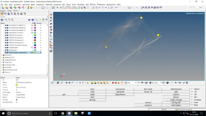
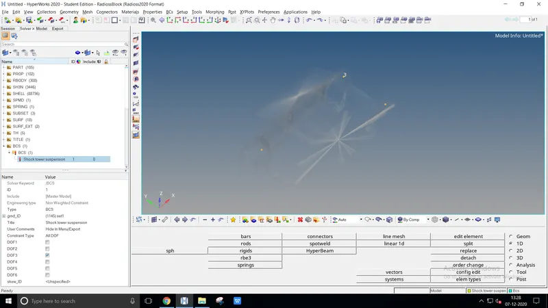
Create a rigid body with boundary condition z-axis on the suspension shock showers
Create rigid body 1D > rigids select the following condition listed above
Create BCS on solver by indicating nodes on the grnd_ID
Impactor boundary conditions :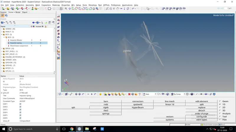
Create a BCS on the spring of the impactor by fixing all DOF
Creating BCS, Create > Boundary conditions > BCS create a grnd_ID as node
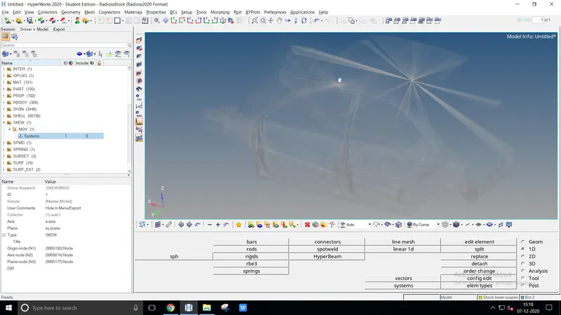
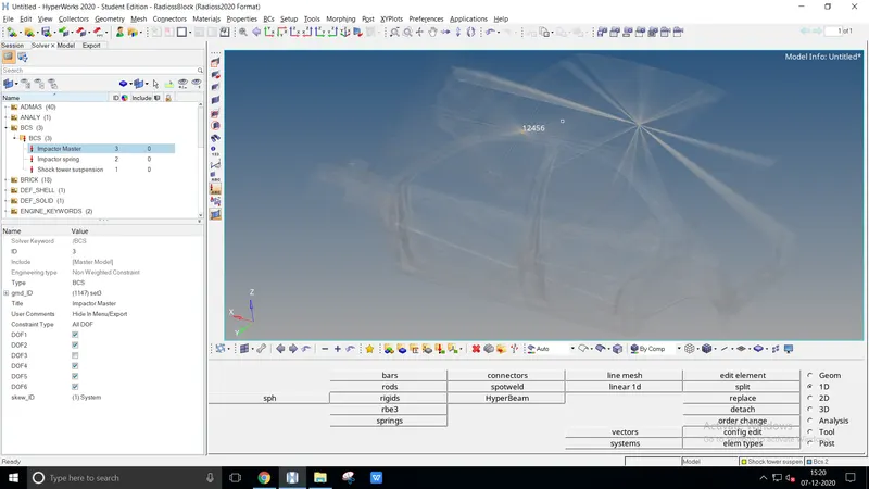
Create a skew movement Create > skew > move to define the impactor direction as the local axis
Create a BCS for the impactor component with fixable DOF by defining the skew_ID
Imposed Displacement :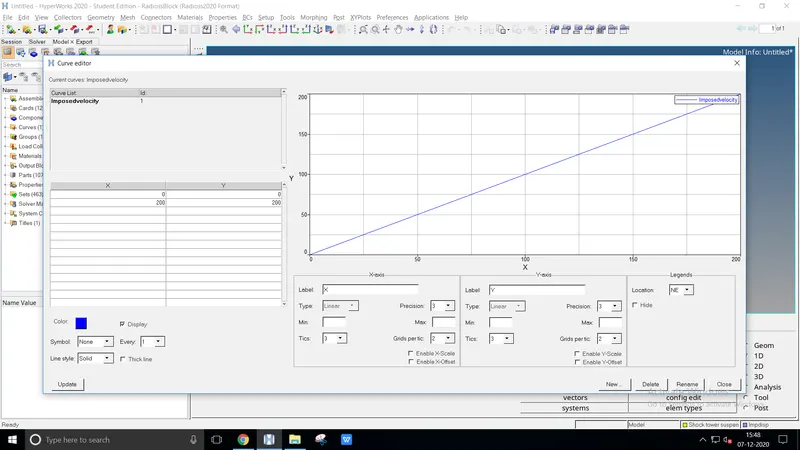
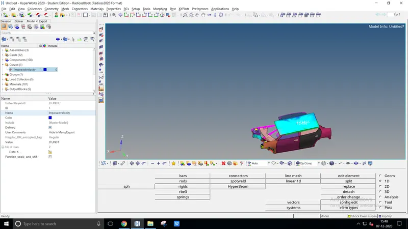
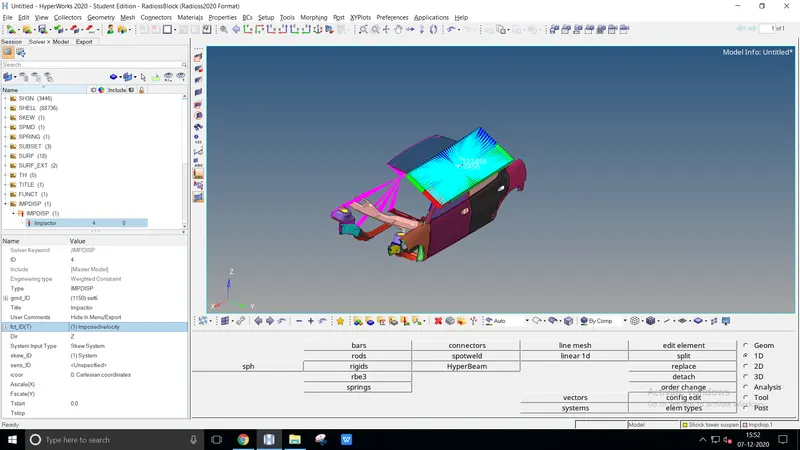
Creating a displacement for the impactor with respected graph value
From the model, Create > Curve provide a name and plot the graph value
Create a displacement, Create > Boundary condition > IMPDISP mentioned each entity_ID clearly
Control cards :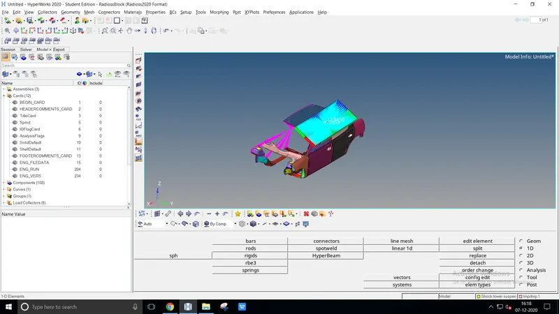
The control cards have already existed on the given model
The image represents the file cards of the model
Engine File :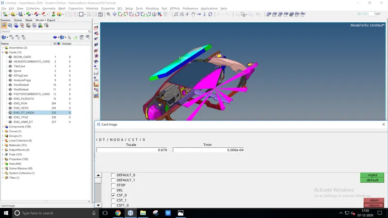
For constant nodal time step create ENG_DT_NODA
Select CST_0 and enter the constant values Tmin-0.0005 & Tscale-0.67
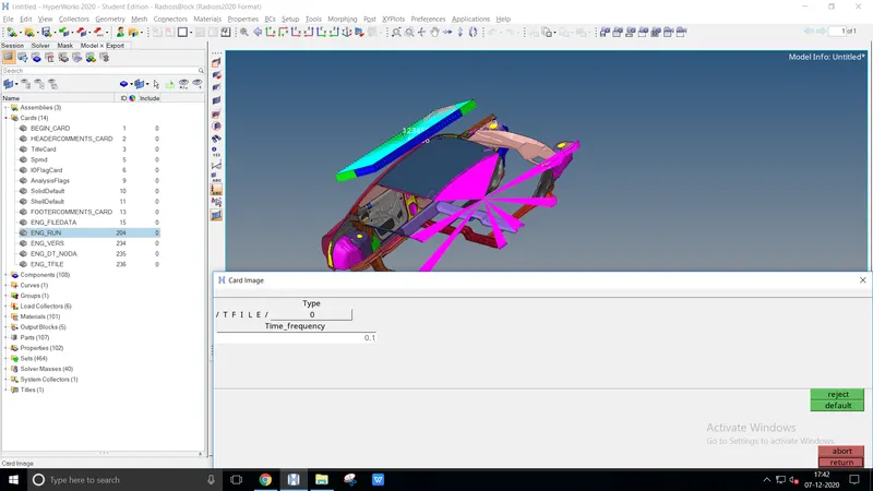
For time-history every 0.0001 seconds create ENG_FILE
Enter the time_frequency value as 0.1ms
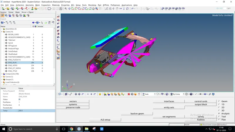
Change existing ENG_RUN, Tstop value as 200ms
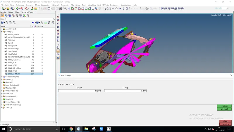
Create an animation file every 0.005 seconds, ENG_ANIM_DT Tfreq - 5ms
Include selected output in animation files :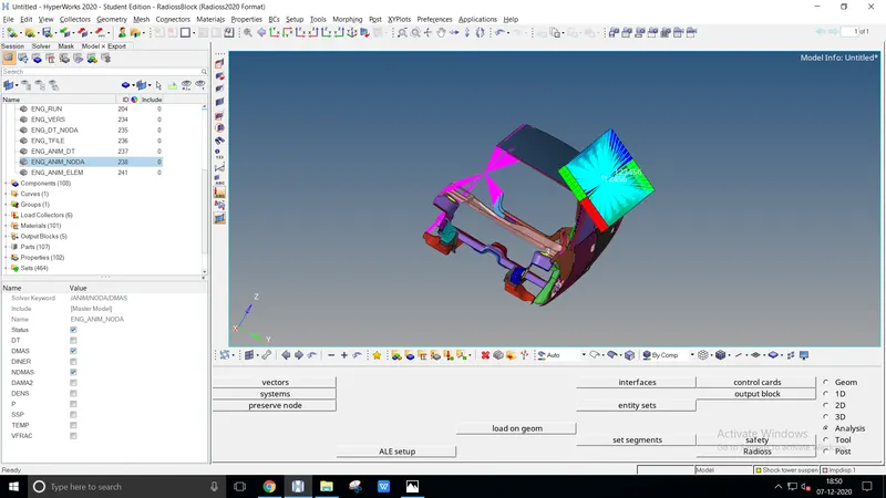
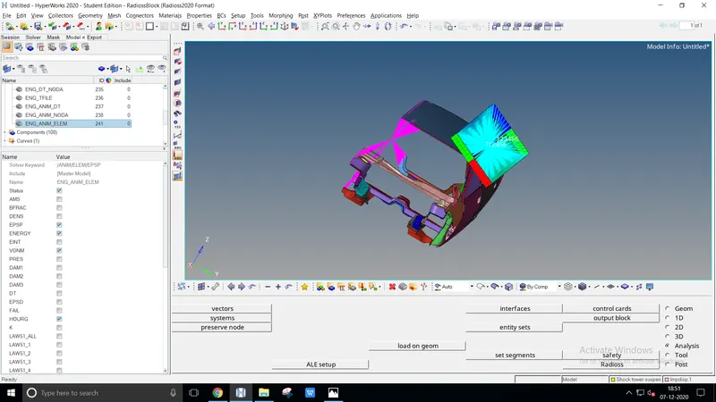
Select the required animated output files from ENG_ANIM_NODA & ENG_ANIM_ELEM
By enlisting required files we could get output graph data
Free Connectivity :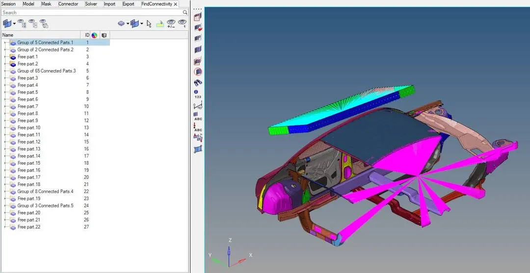
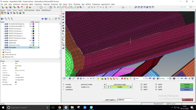
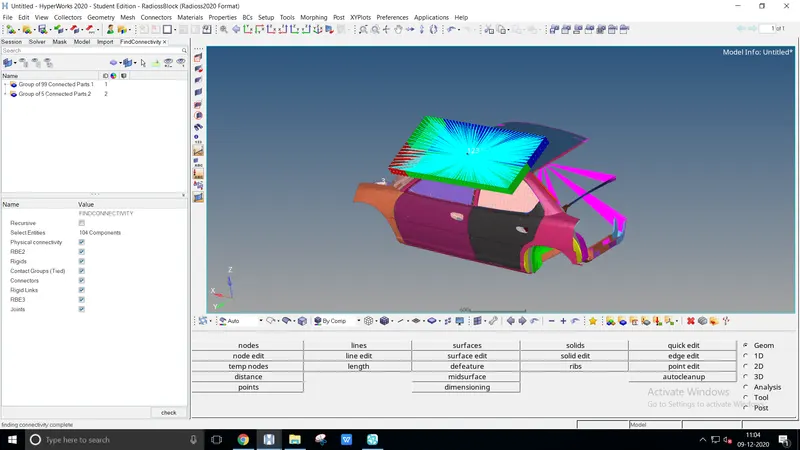
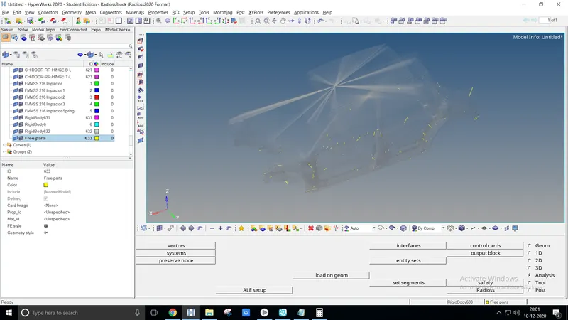
The free parts are availed at each model, connect those free parts using Rigids
Opening Rigids 1D > Rigids select node as calculative, multiple nodes, select nodes
Select the nodes as mentioned in the Find connectivity tab and finally end up the group into two ( Car ) & ( Impactor )
Simulation :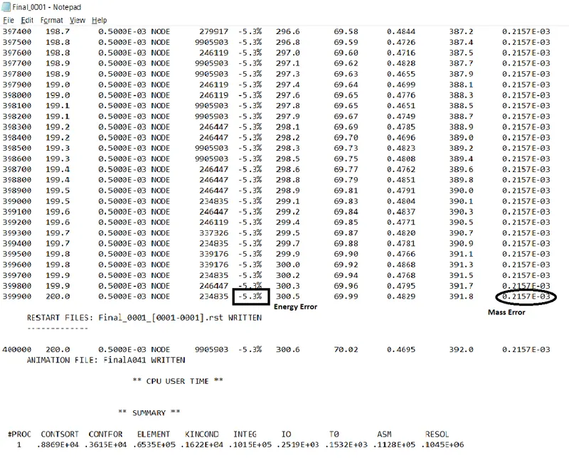
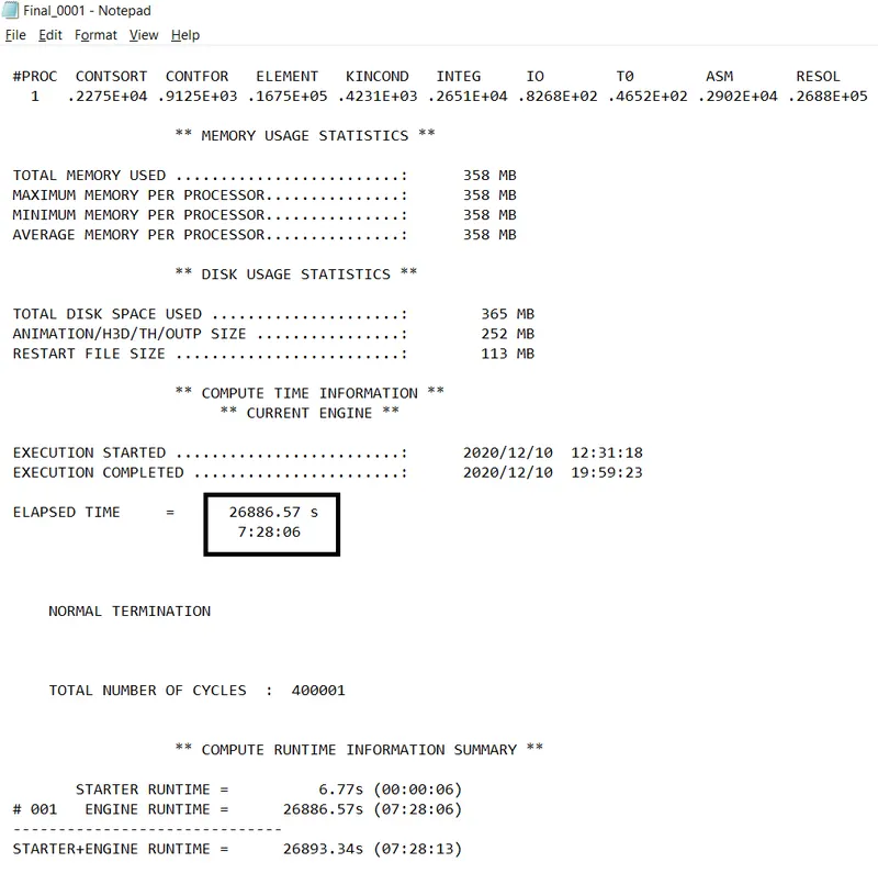
Check the simulation process by ensuring the data cards, given condition and save it at the properly at the defined folder
The simulation energy error should be below -5.0% for better results, 10-15% of the ideal value. The determined model values are energy error -5.3%, mass error 0.2157E-03
INFERENCE
Force vs Displacement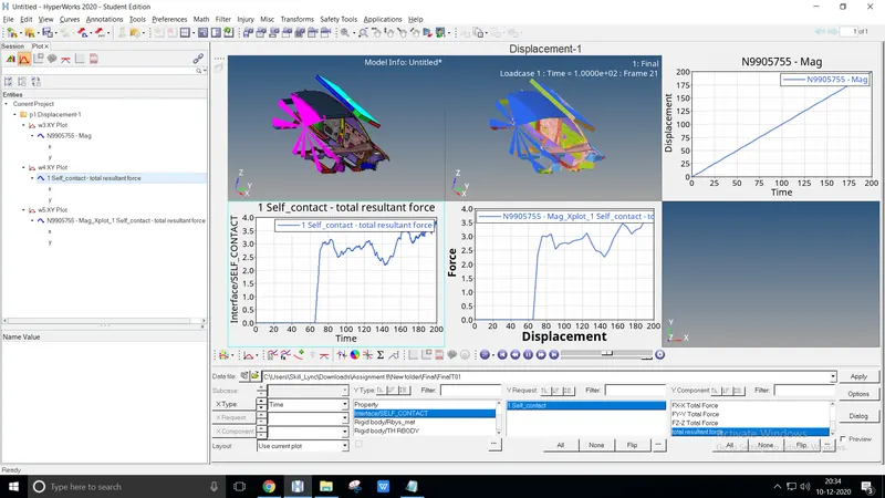
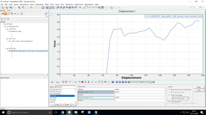
To plot the given file using Node displacement and Resultant force
After the simulation, open the HyperWorks model with multi-tab open the h3D file in Hyperview
Use the Build plot with result type as Displacement > Mag, point the impactor node, and hit apply to view the nodal graph
Plot the Resultant force graph with X-type as time, Y-type as Interface/Self contact with the Y-component as the total resultant force
And finally Cross-plotting the Two curve by Math > Two curves, select the curve-x as Nodal displacement and curve as the resultant force 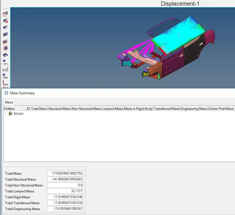
The product of the unloaded weight of the vehicle and acceleration due to gravity, GVW (Gross Vehicle Weight)
The mass of the body (BIW) is 174.052 Kgs, GVW is calculated as 3*174.052*9.81 = 5122.35N i.e., BIW is less than the target load
Energy vs Time curve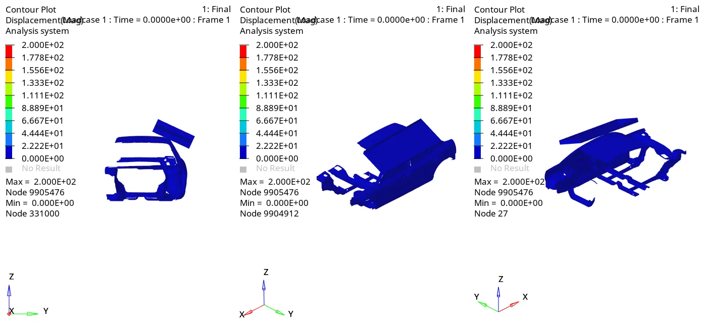
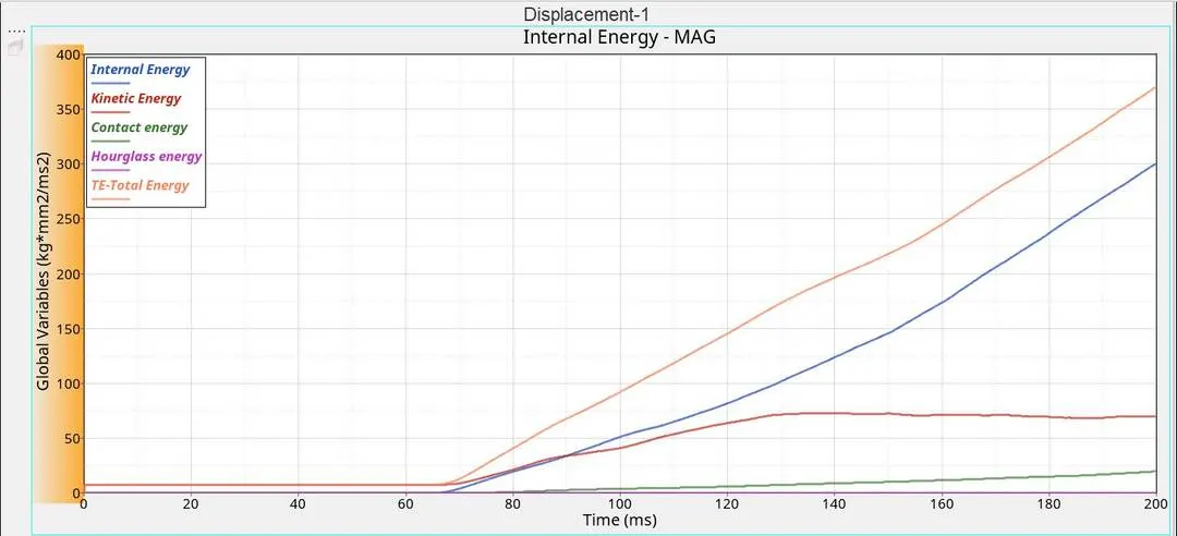
The Global variables determine the Internal energy is absorbed during the Impactor hit by 299.71 Joules
The Kinetic energy gets dropped under a motion passes through the Impactor by 69.95 Joules
The Contact energy is less comparatively because of the low velocity up to 193.69 Joules
The Hourglass energy is inversely proportional to the total energy of 370.28 Joules
CONCLUSION
From the above cases, the energy error didn't exceed the critical scale
To rectify it, visualize the existing model and connect the free parts accurately