Project 1 - 2D meshing on the instrumental Panel
AIM:
- To check for the geometrical errors and mesh with the given element quality criteria
- To assign the thickness after meshing the component without fail
|
S.No |
Quality Criteria |
Value |
|
1 |
Target/Average length |
4 |
|
2 |
Minimum Length |
2 |
|
3 |
Maximum Length |
6 |
|
4 |
Aspect |
3 |
|
5 |
Warpage |
15 |
|
6 |
Skewness |
45 |
|
7 |
Jacobian |
0.7 |
|
8 |
Minimum Quad Angle |
45 |
|
9 |
Maximum Quad Angle |
135 |
|
10 |
Minimum Tria Angle |
30 |
|
11 |
Maximum Tria Angle |
120 |
|
10 |
Tria Percentage |
15 |
Procedure:
Importing Model
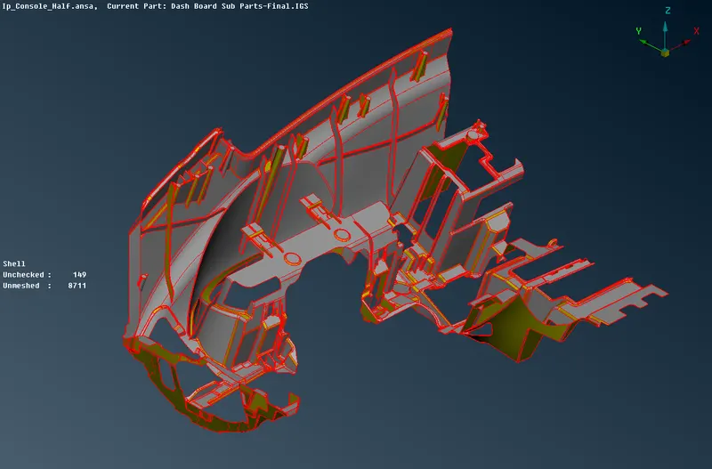
- Import the instrumentation panel model from the existing location into the ANSA. The instrumentation panel model contains five individual components as shown below,
Geometry Check
The first step after importing the model is to properly analyze and understand the geometry. When a CAD model is imported into the ANSA, there might be several geometrical errors like missing/distorted surfaces, intersecting surfaces, etc. due to the format conversion process or inherent bad model. And, it is important to clear all these errors before starting meshing. So, the next step is to clean up the geometry. In ANSA software there certain kinds of tools used for geometry clean up, 2D meshing, and different types of solvers to define certain problems. Initially, the CAD model should import into the software and check for geometry is done to get rid of any of the errors found. There are certain types of errors like triple cons, single cons, unchecked faces, convex cons, etc., These errors could be fixed automatically and also manually
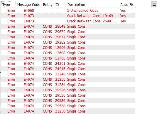
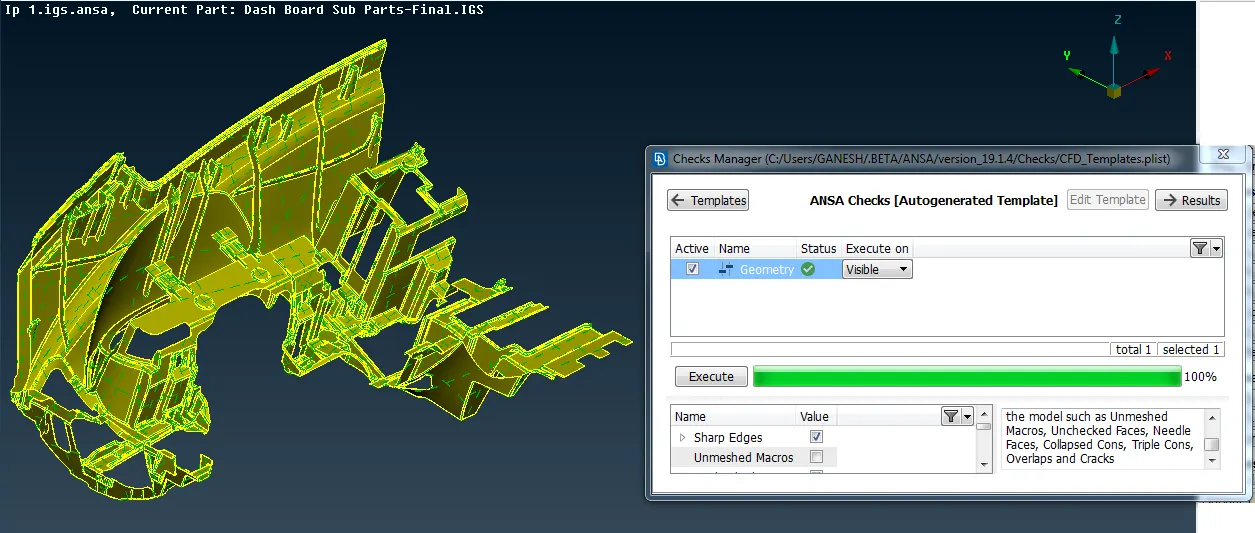
- To ensure that all the surfaces are connected properly Faces>Topo tool is used for all the edges of each component at a time. Next, a geometry check is performed by going to Checks>Geometry and running it for parameters as shown in the image below. Another image shows the errors detected
- Most of the errors were fixed automatically by right-clicking on the error>fix. Next, the orientation of all the faces is modified by going to Faces>Orient to ensures that all faces are oriented similarly
Mid-Surfaces
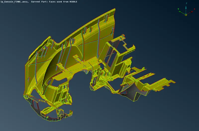
To extract the mid surfaces for each component and keep them in separate property id. the mid surfaces are extracted using the manual method, Faces>offset i.e. offsetting the surfaces of either face to the middle. First, the thickness of each component is measured using the Measure tool from Utilities>Measure. Instead of meshing the whole 3D body, its midsurface is extracted and the meshing (shell mesh) is performed over it. This reduces the simulation time of the component to a large extent
- Small entities such as ribs needed to be carefully extended up to the neighboring entities
- Since the dog houses are of thickness more than 5mm, these can't be mid-surface normally
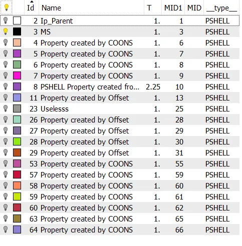
- Different PIDs are provided to the parts based on their thicknesses. Finally, variable thicknesses are assigned
Meshing
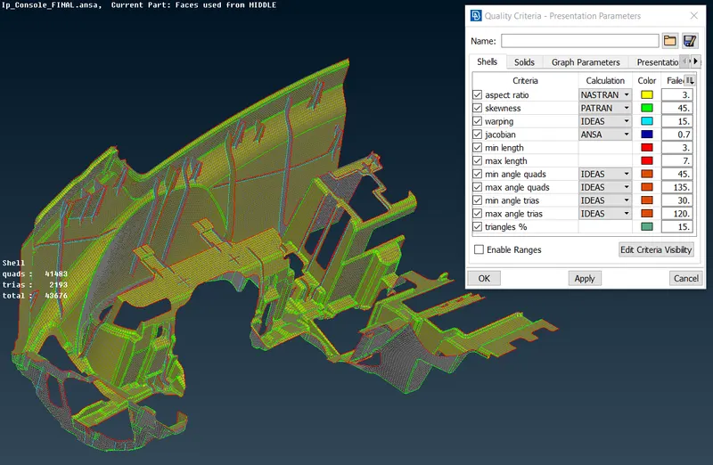
Next, meshing is done using the Mesh generation>Best. This tool generates the mesh using the best algorithm applicable. Then, the created mesh is refined using the Shell Mesh>Reconstruct tool. It is ensured that there are no rotating quads. Also, trias are kept as low as possible. While dealing with trias, the following things need to be ensured,
- No opposite trias
- No trias on a feature
- No trias touching the edges
- Low concentration of trias in a region
- No back to back trias touching each other
To deal with trias, the following tools are used,
- Elements>Swap, to move the tria left or right
- Elements>Join, to join two trias to make a quad
- Grid>Paste, to paste the nodes and move tria backward
- Elements>Split, to split an element and move tria forward
Solid transformation
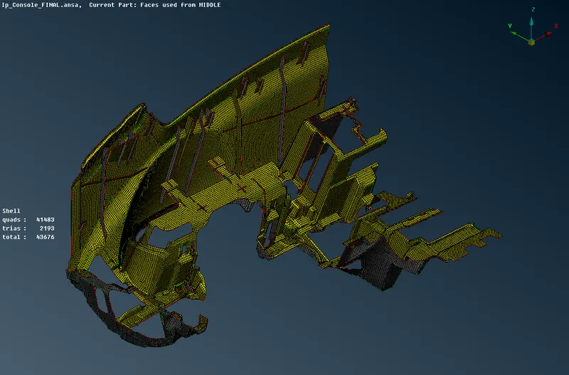
- Then, the mesh is checked for equivalence by changing to the Topo module. The model is checked for any free CONS and pasted using the Topo tool if any. Again, the mesh is checked for quality criteria. Finally, the shell element representation is changed by going to Utilities>Quality Criteria>Presentation parameters and enabling the 'Draw shell as solid'
CONCLUSION:
- As per the given objective geometry clean-up has been done and as per the given quality criteria, the given model meshes accordingly, and thickness is assigned for each part. Tools used are property, checks, mesh parameters, quality criteria, transform, measure. For selecting any surface or faces ENT, PID, Macro Area, feature options are used according to the requirement.
- For masking and unmasking the surfaces or, and, not, inot, all, invert, lock, neighbor options are used. In topo model insert, delete, weld spot, release, cut, delete, set PID, topo, Proj cut, Rm Dbl, offset, orient, fine, etc., In mesh module insert, delete, number, num+/-, length, slide, cut, edge2peri, move, best, remesh, batch, erase, map, smooth, reconstruct, split, etc.,