Week 7 Challenge - Assembly Workbench
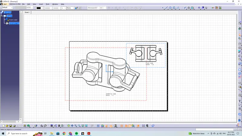
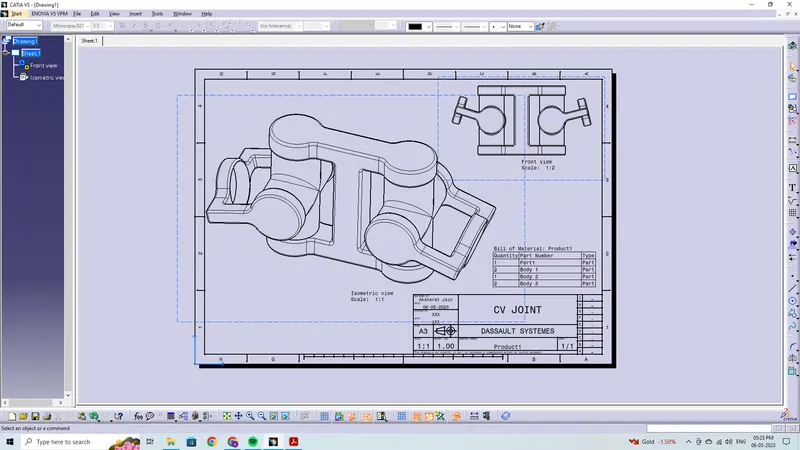
In this week’s assignment, you will have to create 2 assemblies according to the content covered in the course videos. You will be provided with 2D diagrams of the components and you will have to first create the individual part files and then create a complete assembly of those part files in the assembly workbench. After creating the assembly make use of the drafting tools to create a 2D drawing similar to the one given in the assignment folder.
The diagrams for the assignment are provided in the link mentioned below. Assume all the unmarked dimensions as you see fit.
a.) Drawing 1
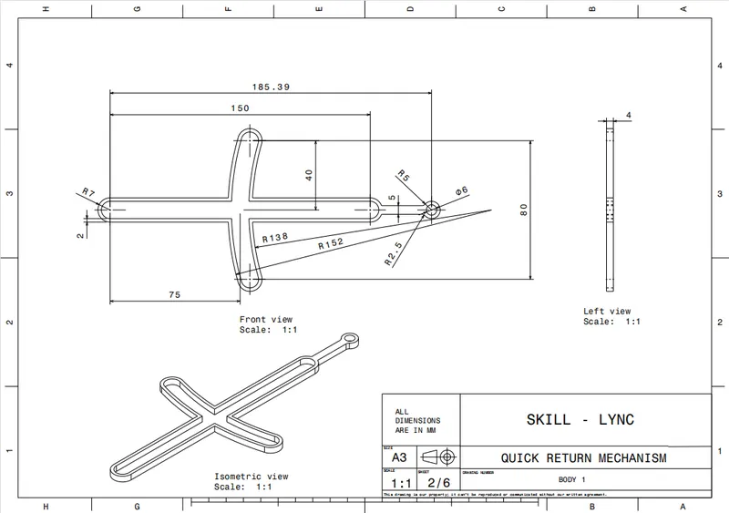
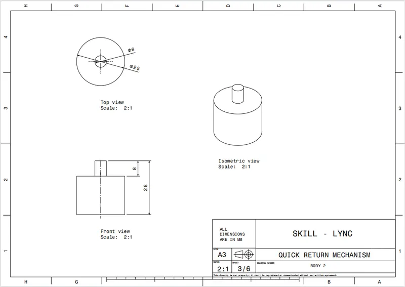
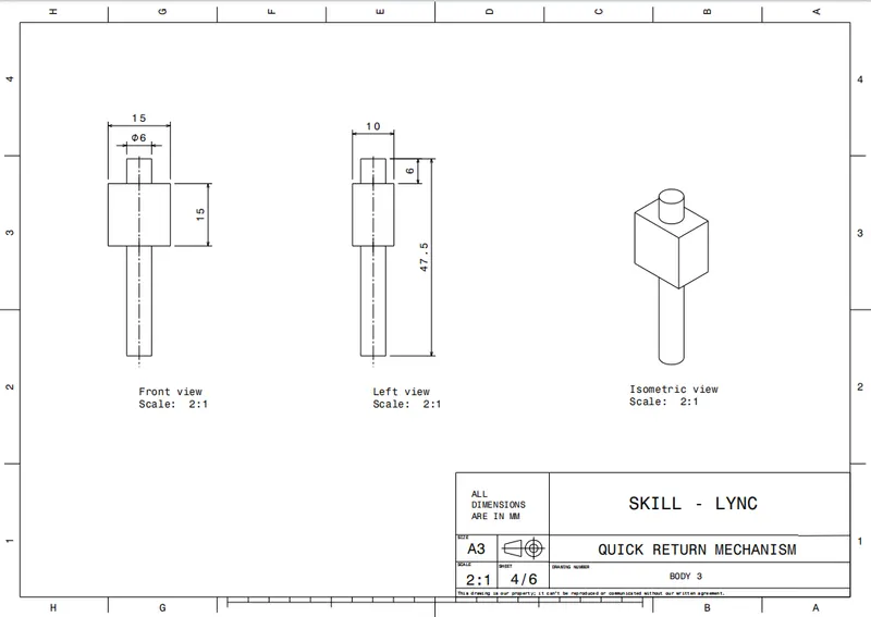
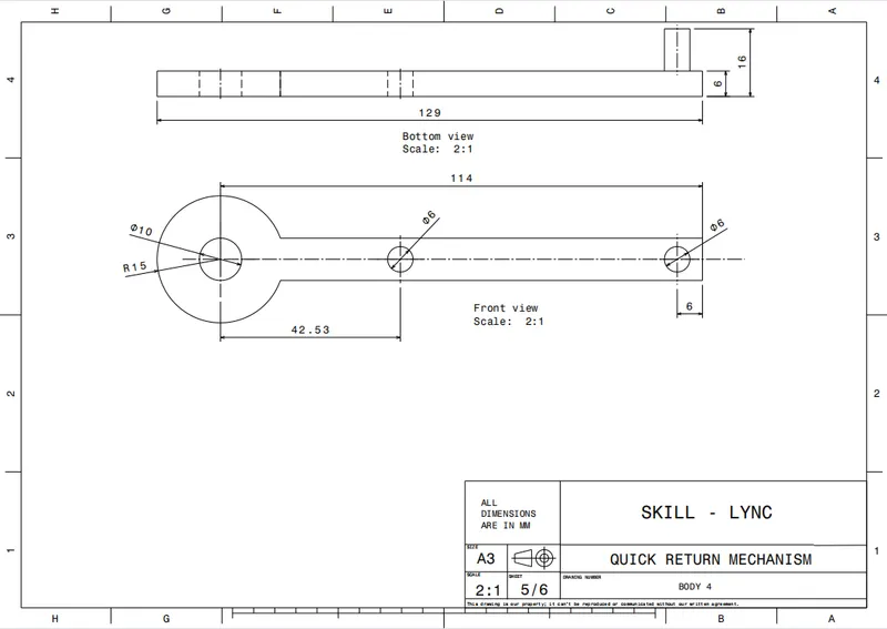
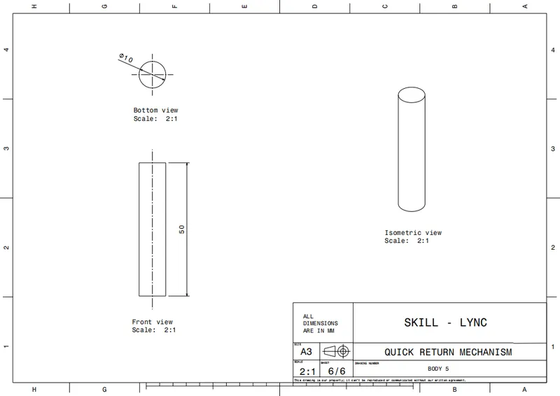
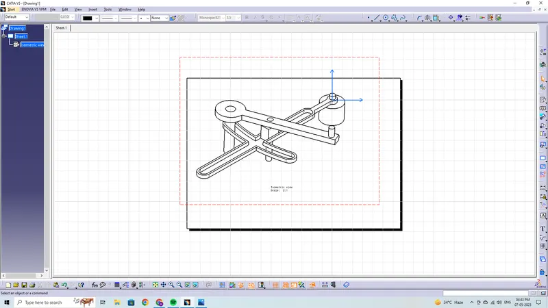
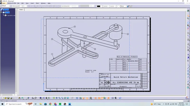
Quick Return Mechanism
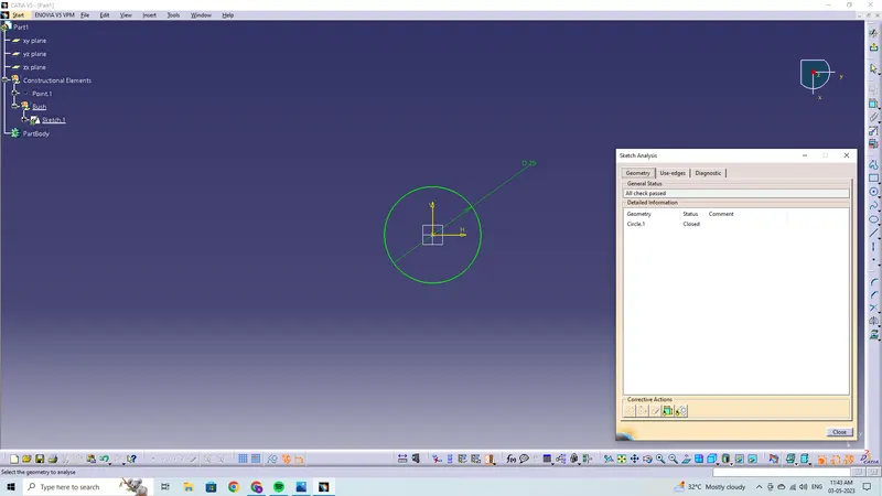
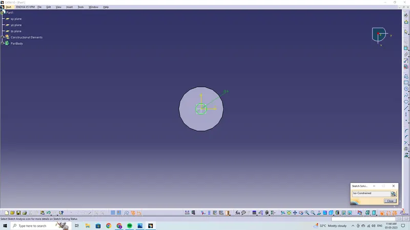
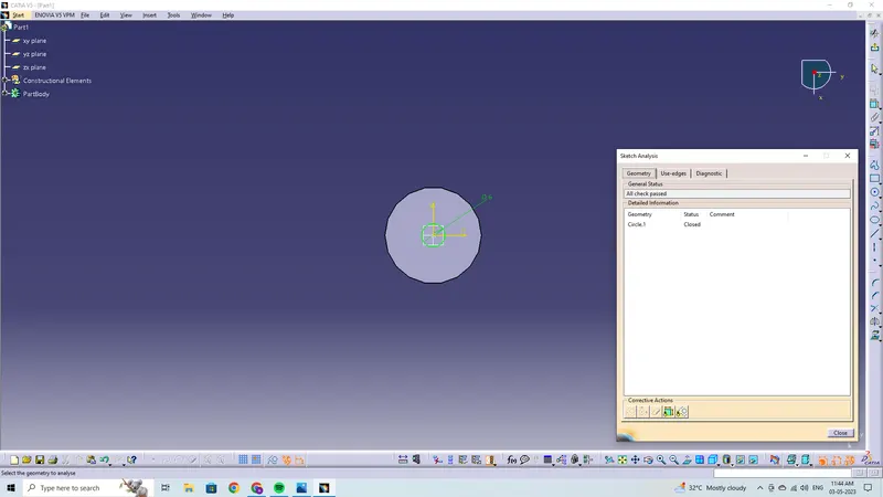
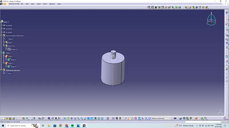
- Prior to establishing an assembly, we must create the parts separately based on the provided drawings.
- In order to create the various sections separately in separate part files, we first open a new part file.
Body 1
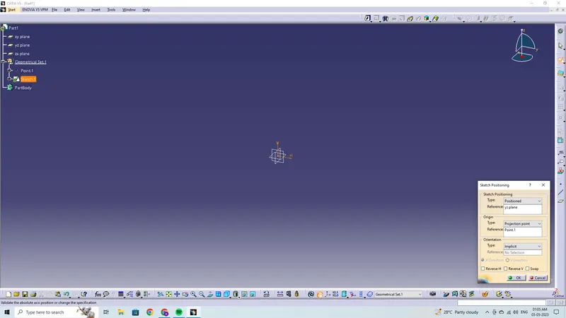
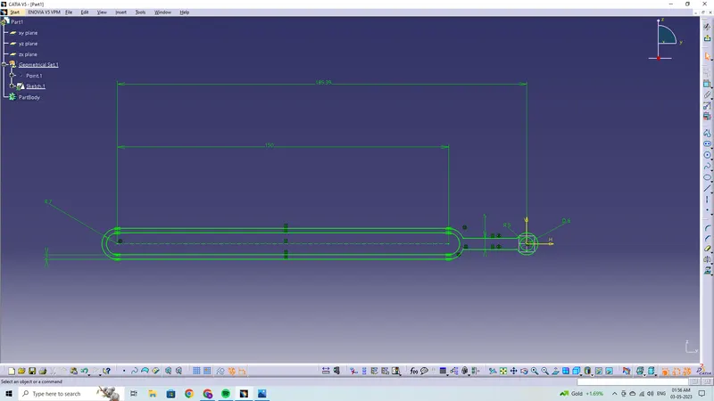
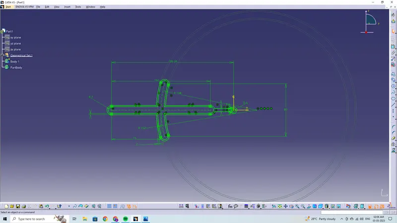
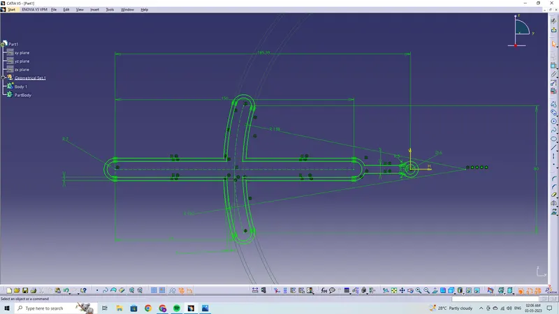
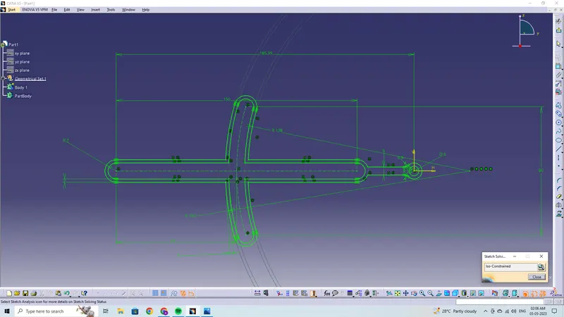
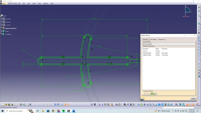
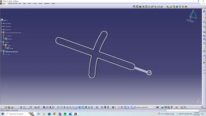
Drawing 1
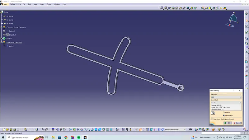
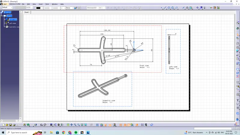
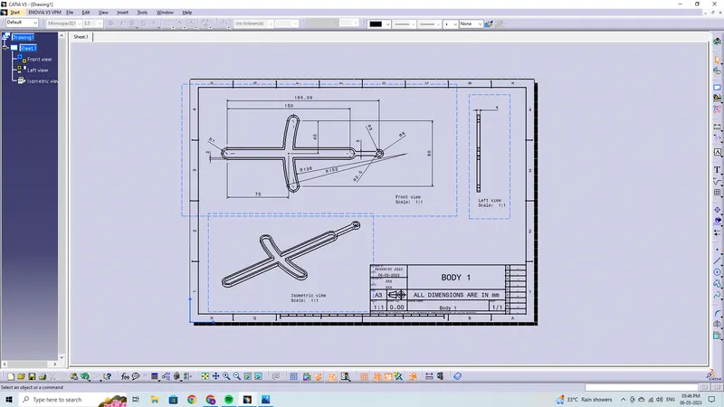
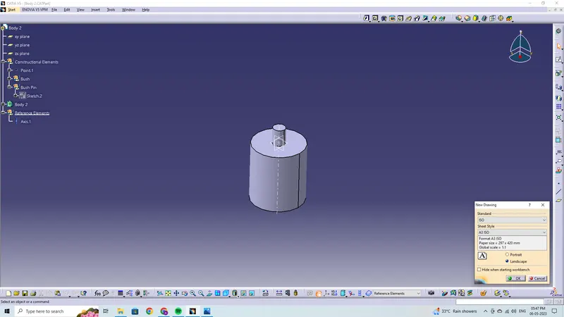
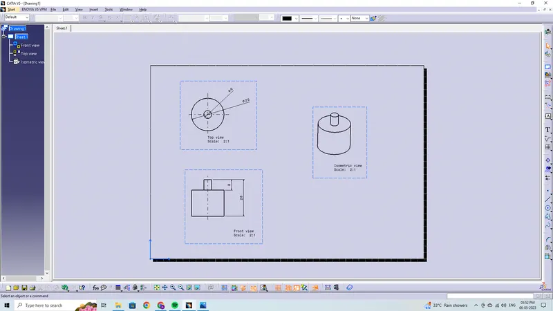
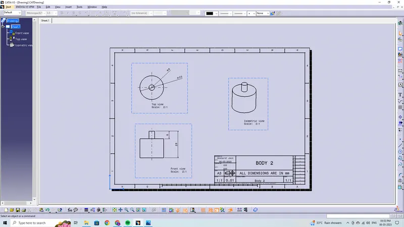
Body 2
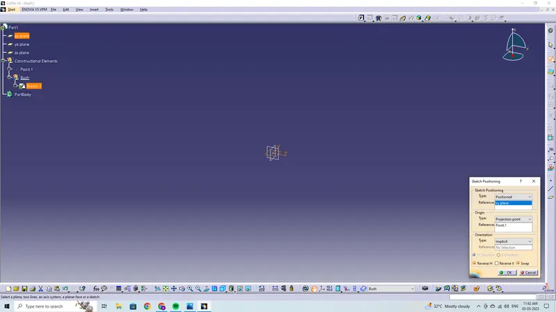
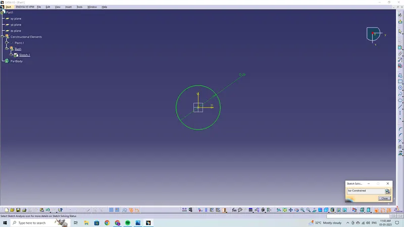
Drawing 2
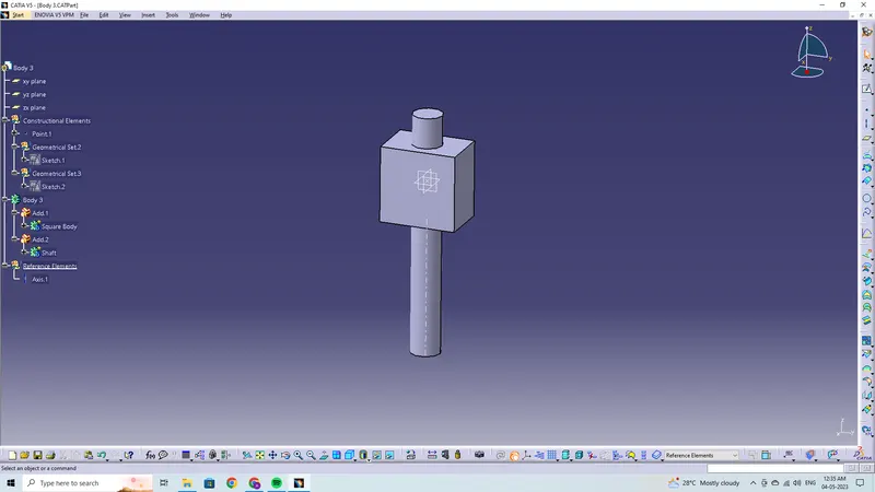
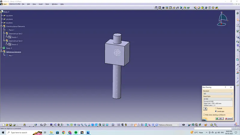
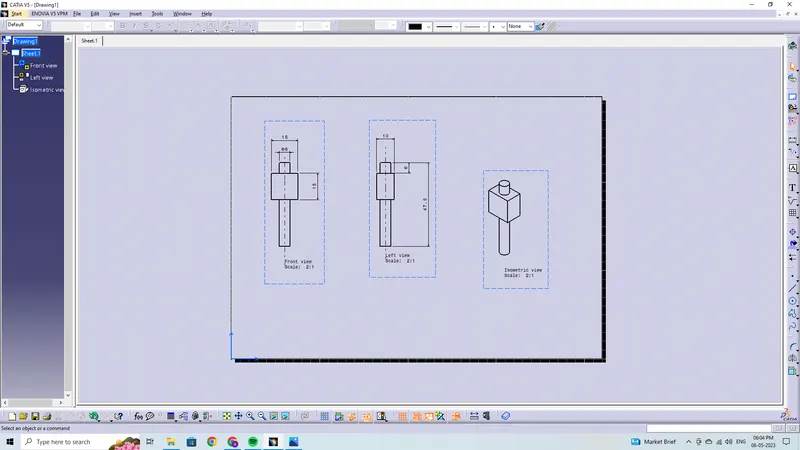
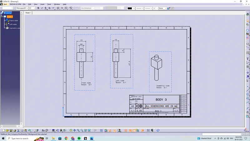
Body 3
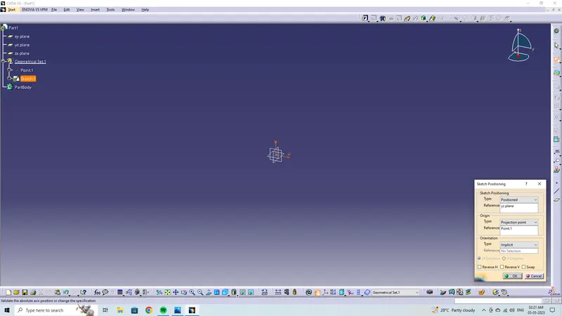
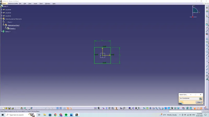
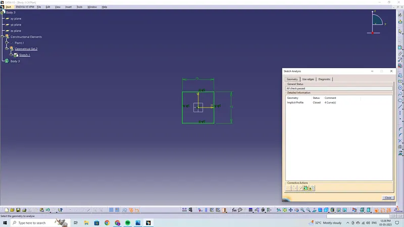
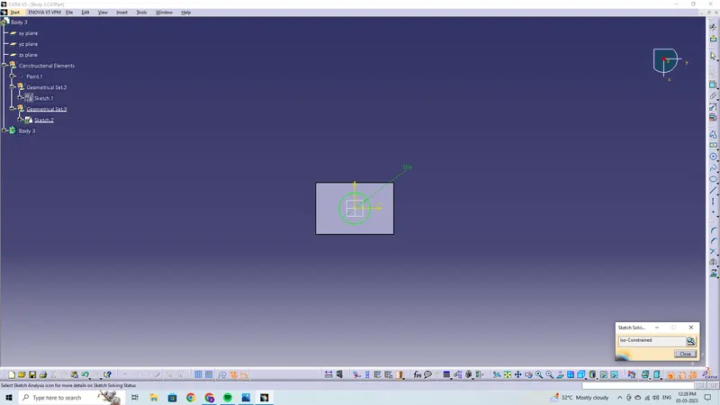
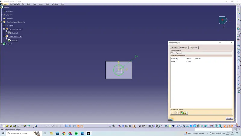
Drawing 3
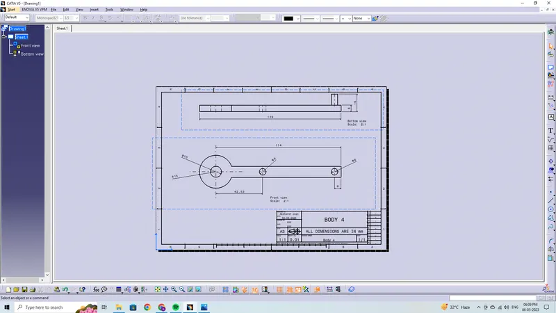
Body 4
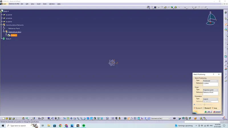
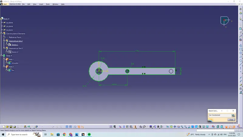
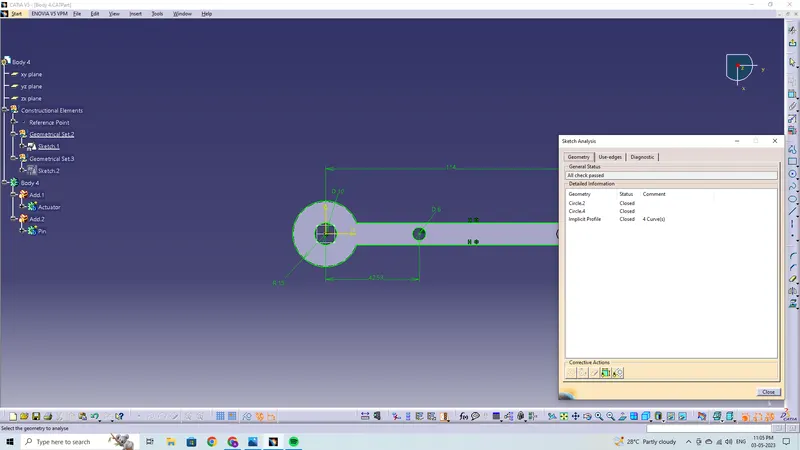
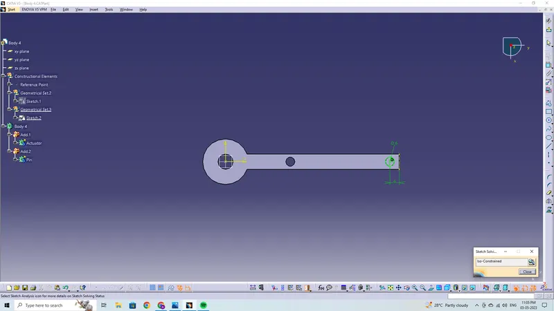
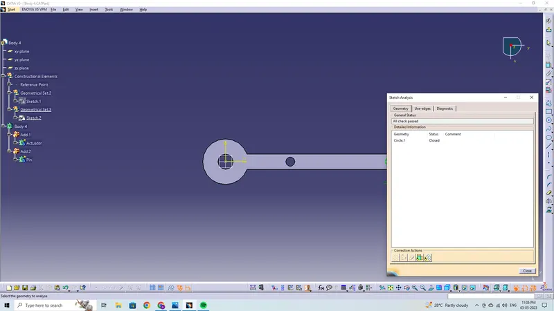
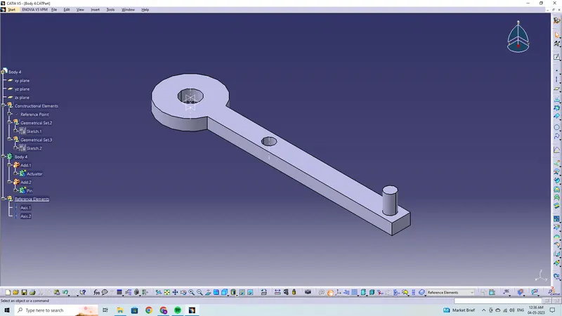
Drawing 4
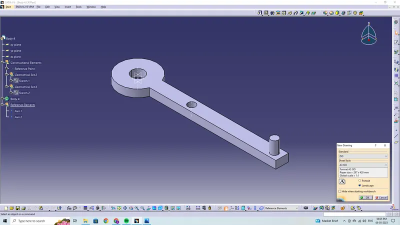
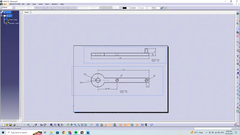
Body 5
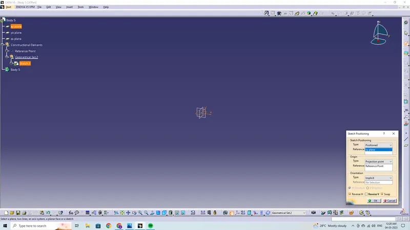
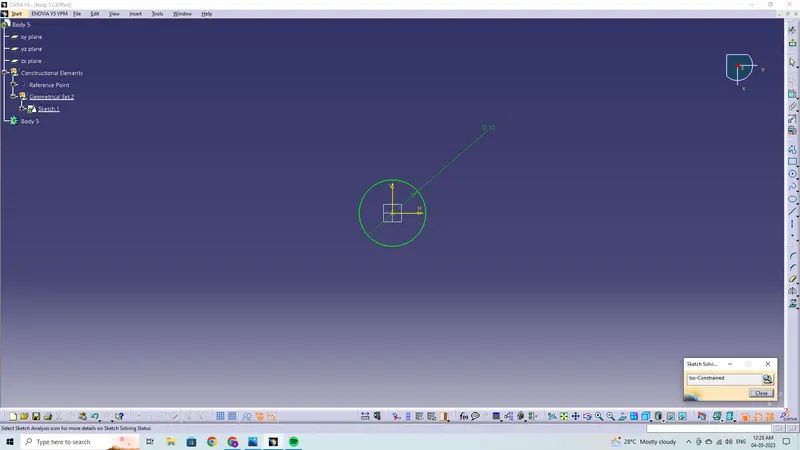
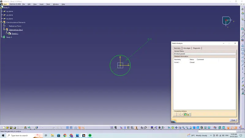
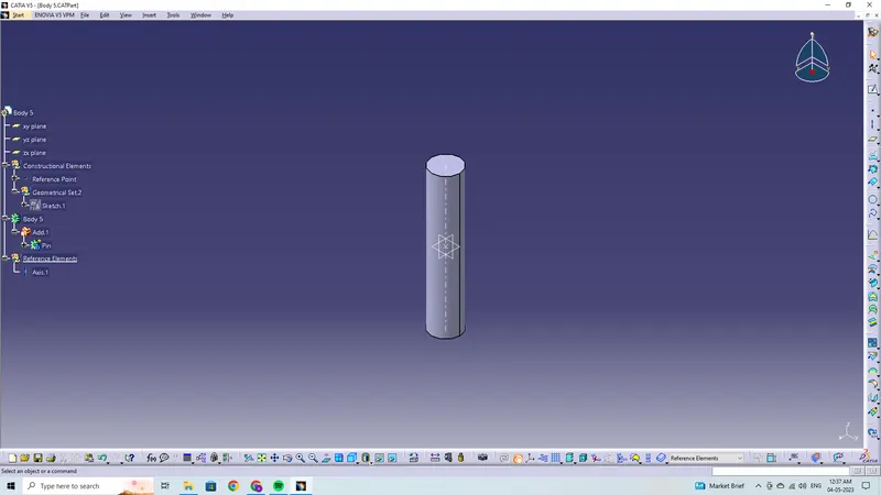
Drawing 5
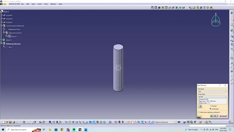
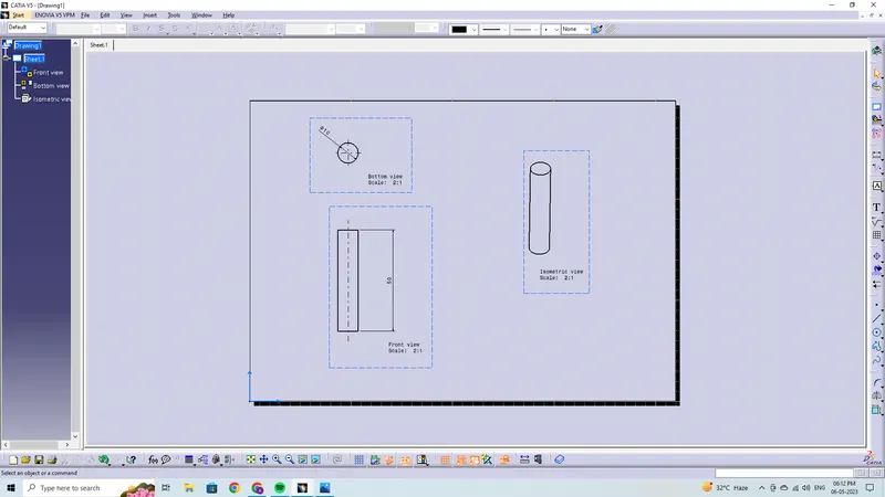
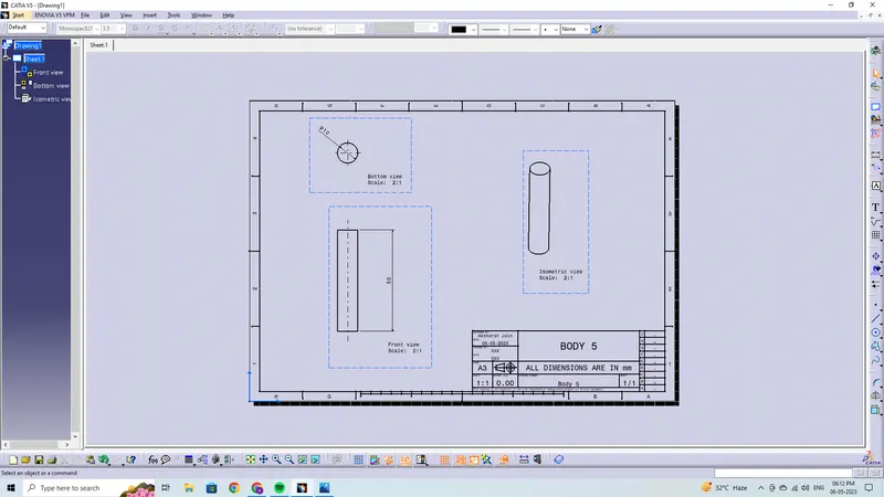
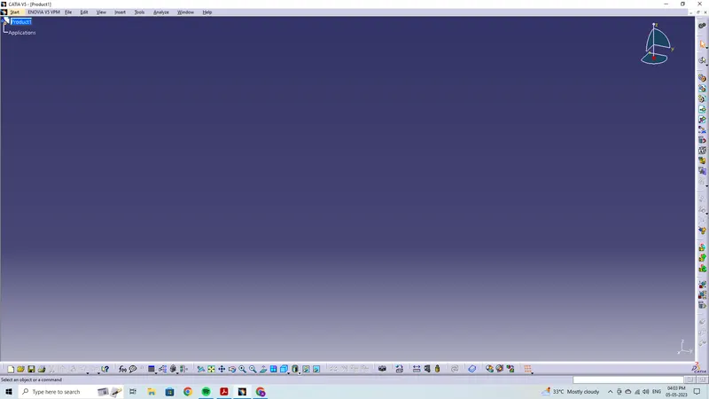
- Then, once the parts are made, a new product file is made.
- Then, using the "existing component option," we load every component into the new product file.
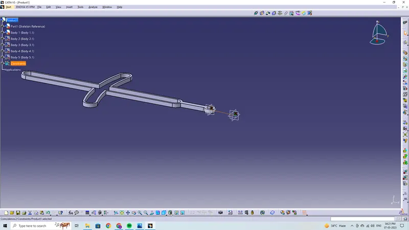
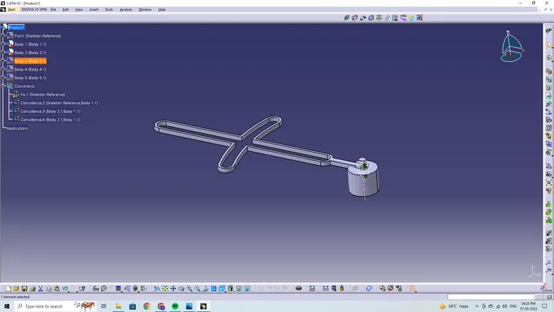
- Next, we choose Part1 (Skeleton Reference) and apply the fix constraint on it.
- Then, we use the coincide constraint to align bodies 1 to the Skeleton Reference because that acts as a origin for the whole assembly.
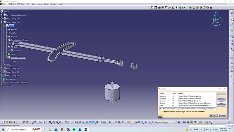
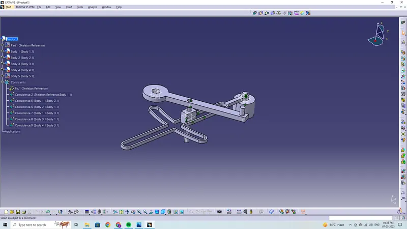
- After that, we use the coincide constraint to align bodies 1 and 2 with the axis/planes/faces.
- The axis/planes/faces of bodies 1 and 2 are then given coincide constraint.
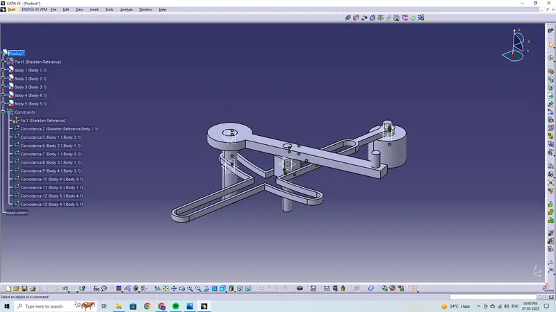
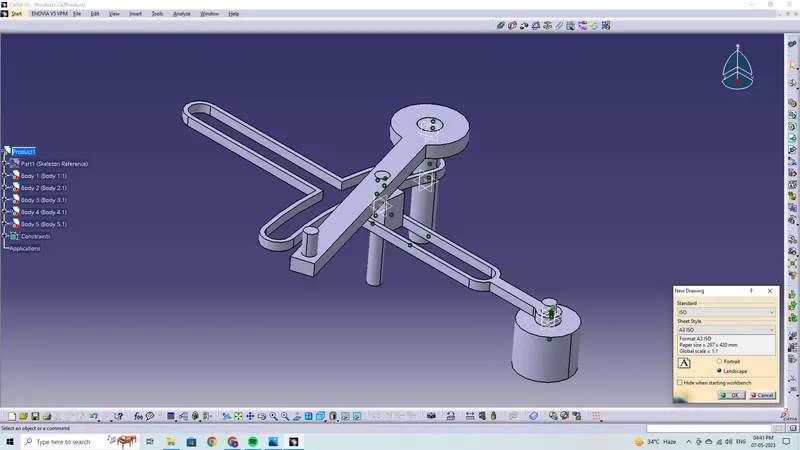
- Similar to this, every component or part is co-ordinated using the coincidence constraint to build the Quick Return Mechanism.
- Finally, we use the explode option to make sure that everything is securely bound.
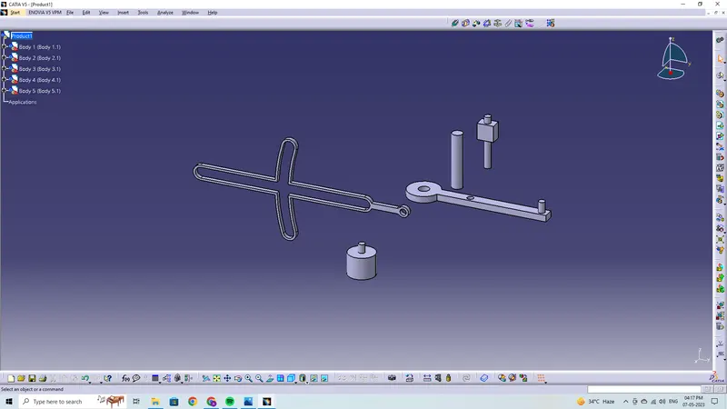
Drawing Final
b.) Drawing 2
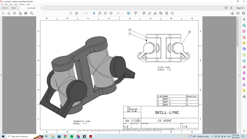
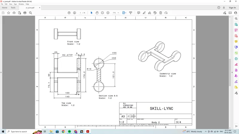
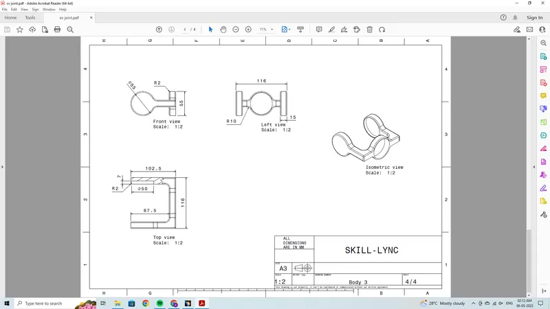
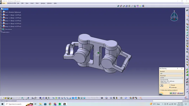
CV JOINT
- Prior to establishing an assembly, we must create the parts separately based on the provided drawings.
- In order to create the various sections separately in separate part files, we first open a new part file.
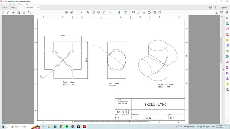
Body 1
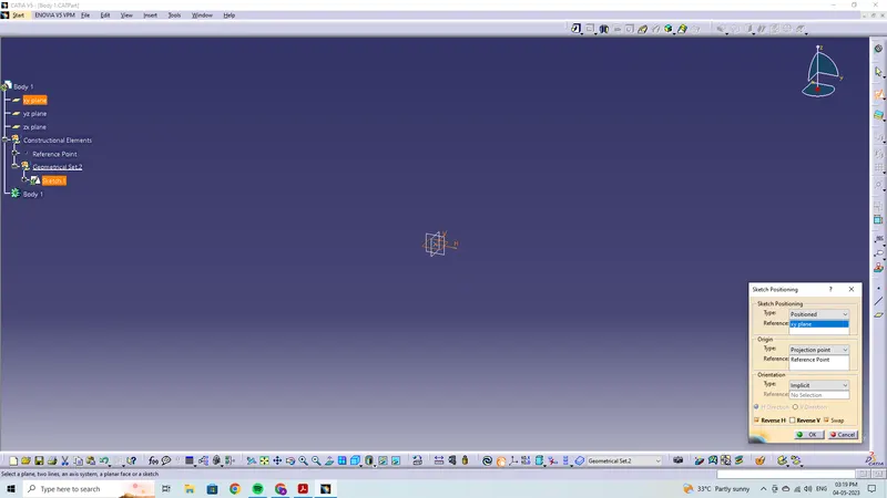
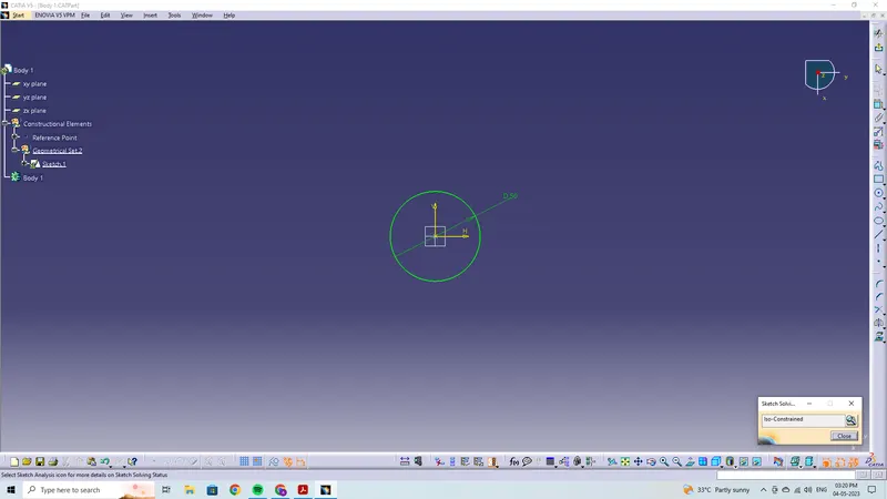
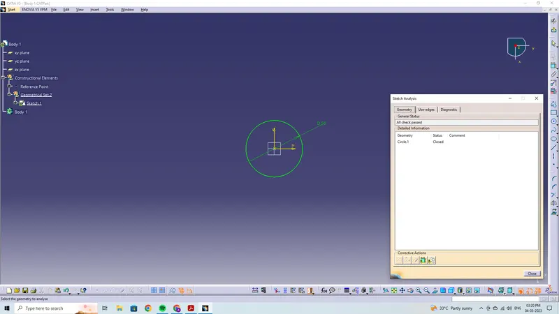
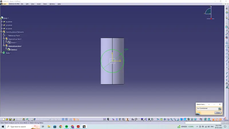
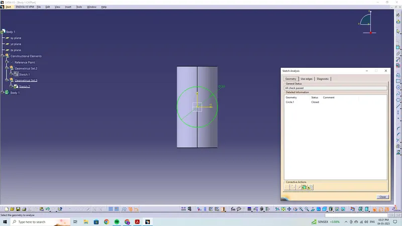
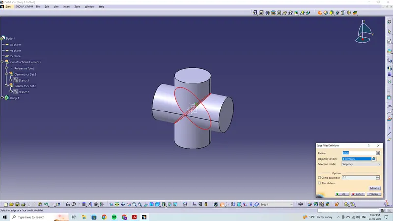
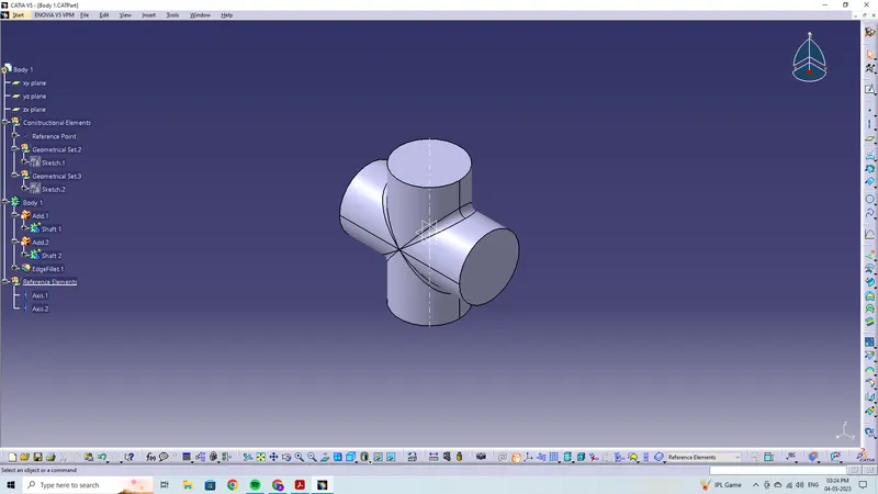
Drawing 1
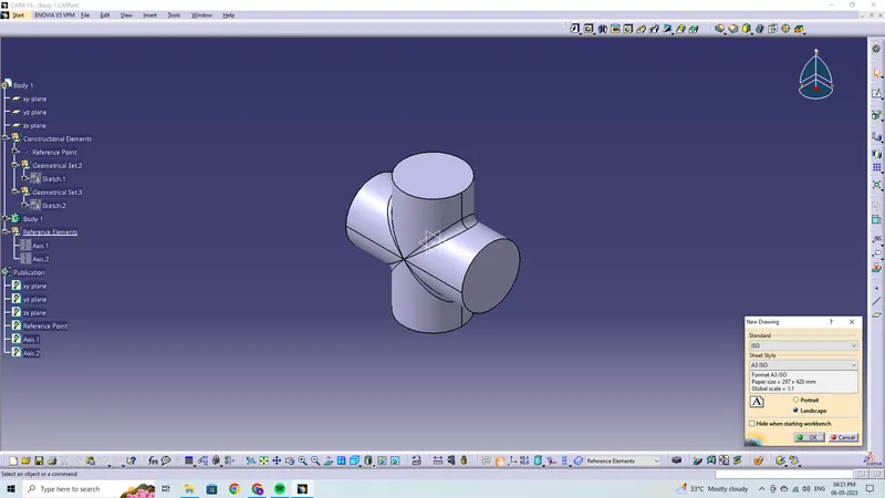
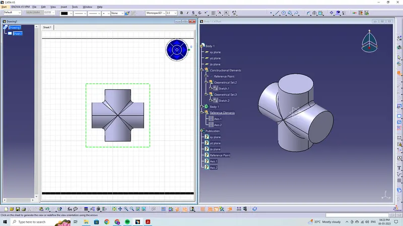
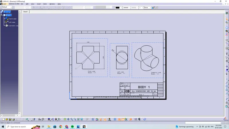
Body 2
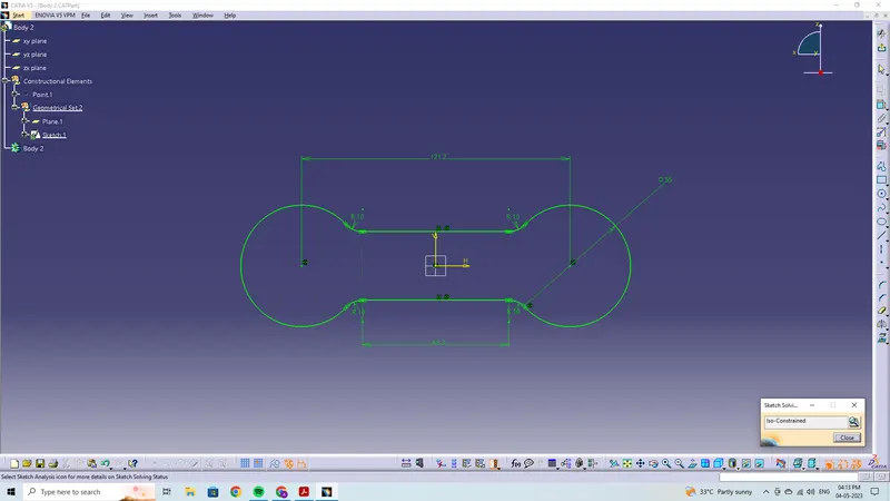
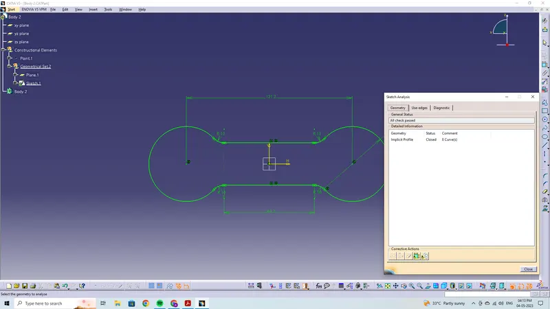
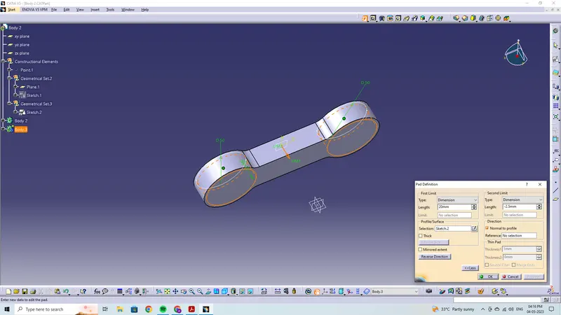
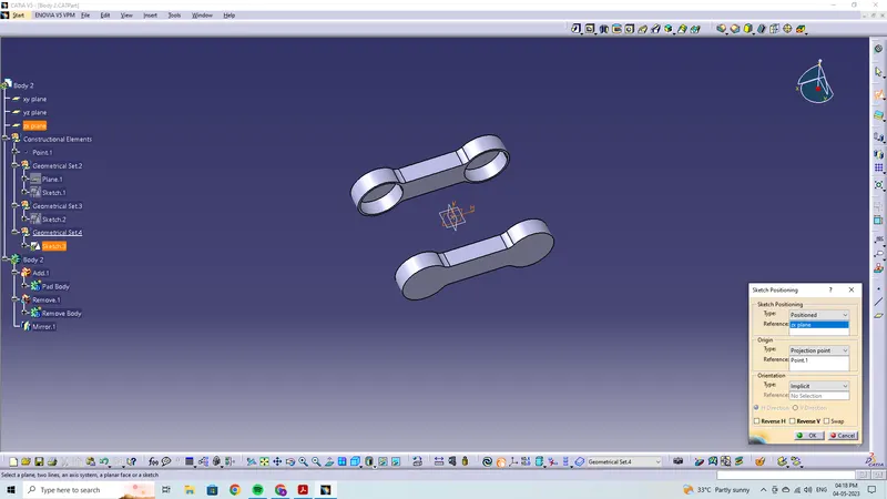
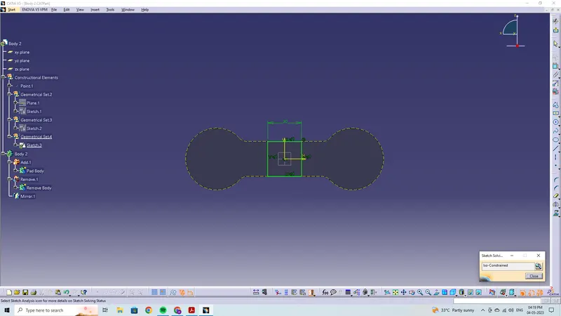
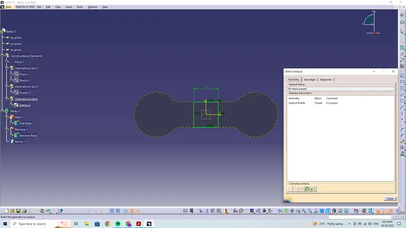
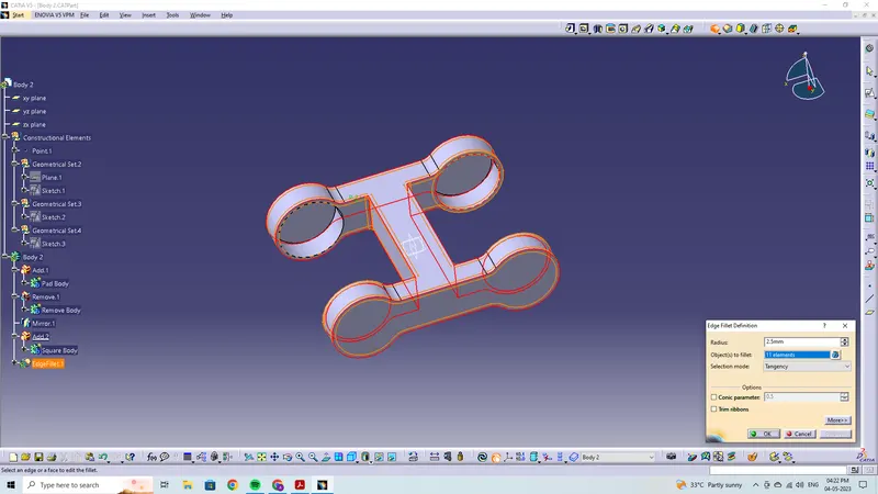

Drawing 2
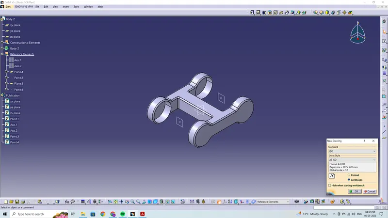
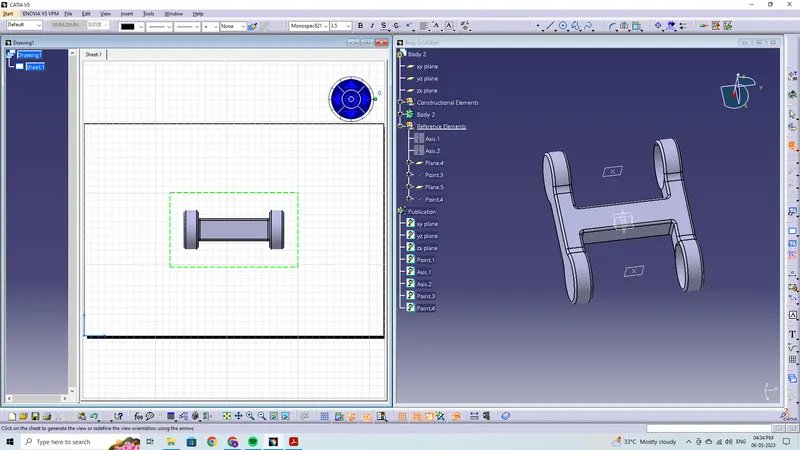
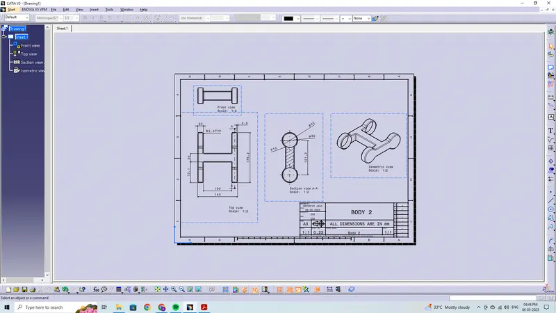
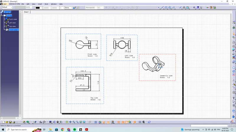
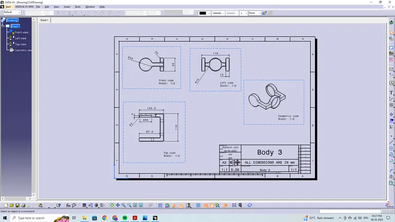
Body 3
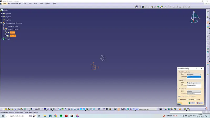
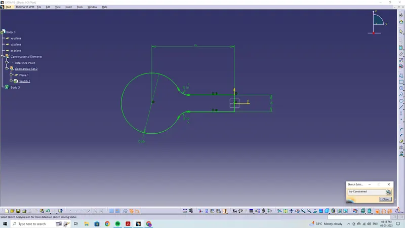
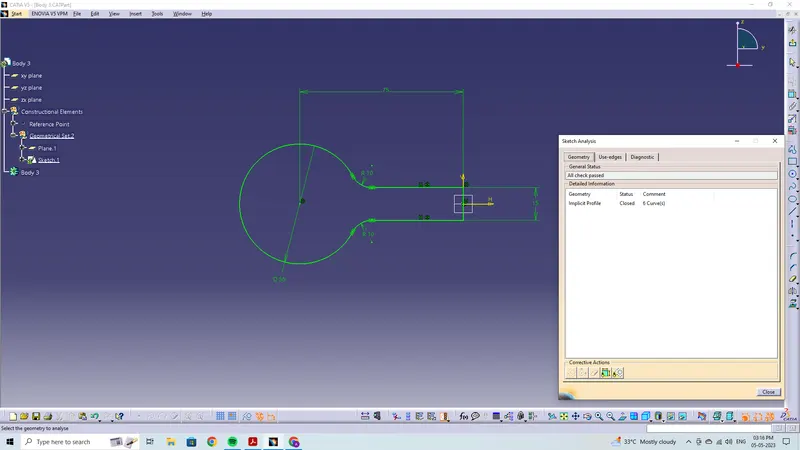
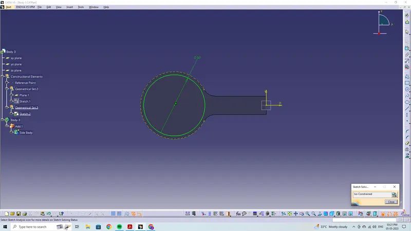
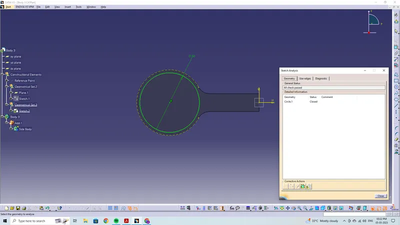
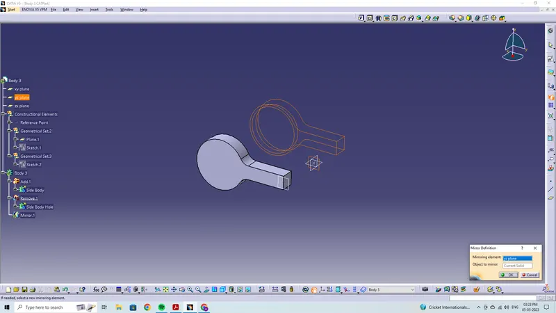
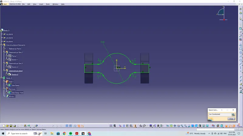
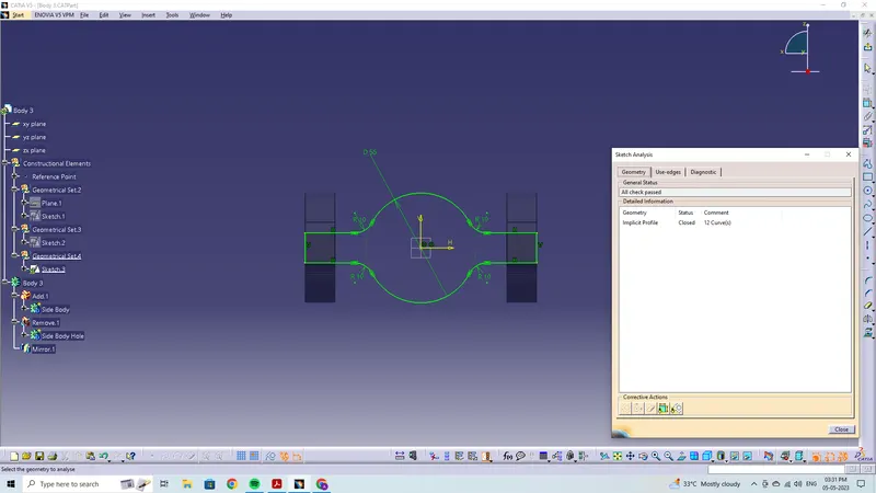
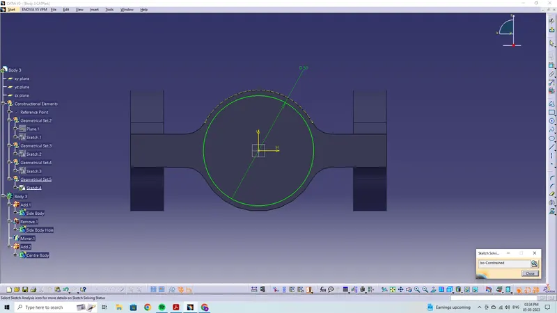
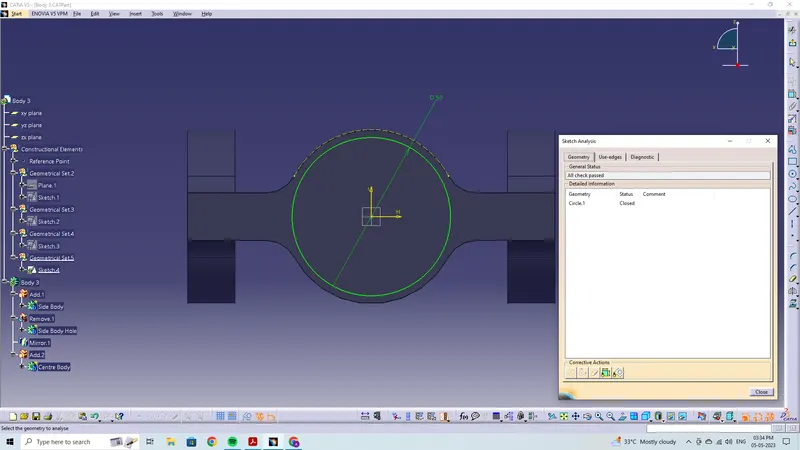
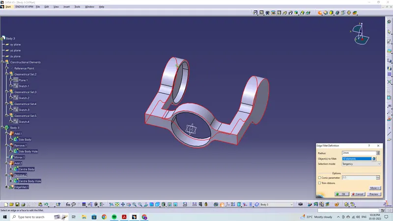
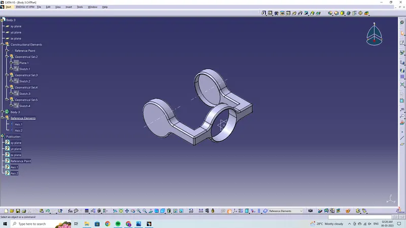
Drawing 3
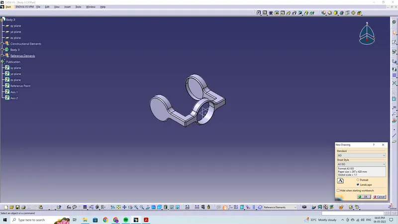
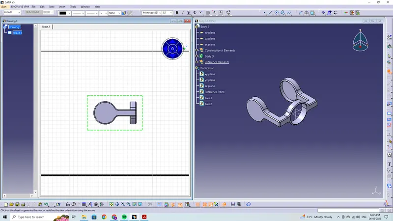
- Then, once the parts are made, a new product file is made.
- Then, using the "existing component option," we load every component into the new product file.
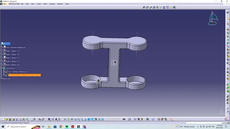
- Next, we choose Part1 (Skeleton Reference) and apply the fix constraint on it.
- Then, we use the coincide constraint to align bodies 1 to the Skeleton Reference because that acts as a origin for the whole assembly.
- After that, we use the coincide constraint to align bodies 1 and 2 with the axis/planes/faces.
- The axis/planes/faces of bodies 1 and 2 are then given coincide constraint.
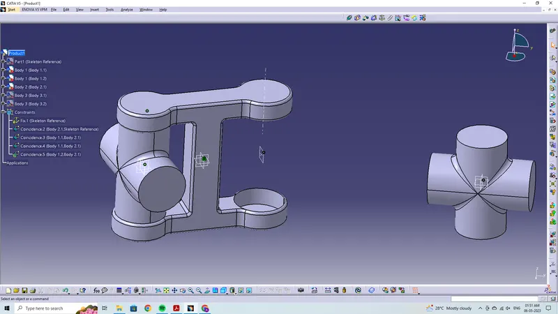
- Similar to this, every component or part is co-ordinated using the coincidence constraint to build the CV Joint.
- Finally, we use the explode option to make sure that everything is securely bound.
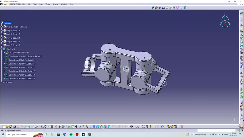
Drawing Final