Roof Design
For the Given Roof styling, create an ASSEMBLY by developing the essential flanges for the outer roof and creating the reinforcements.
Provide appropriate dimensions and check for Draft analysis.
Do a curvature study on the roof and perform calculations to determine the position of the Bow-roofs.
Suggest and implement remedies in the design if the criterion is not full-filling
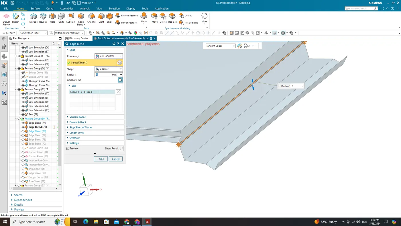
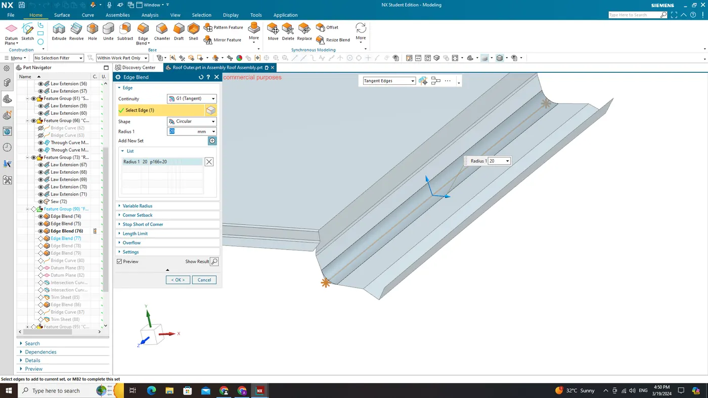
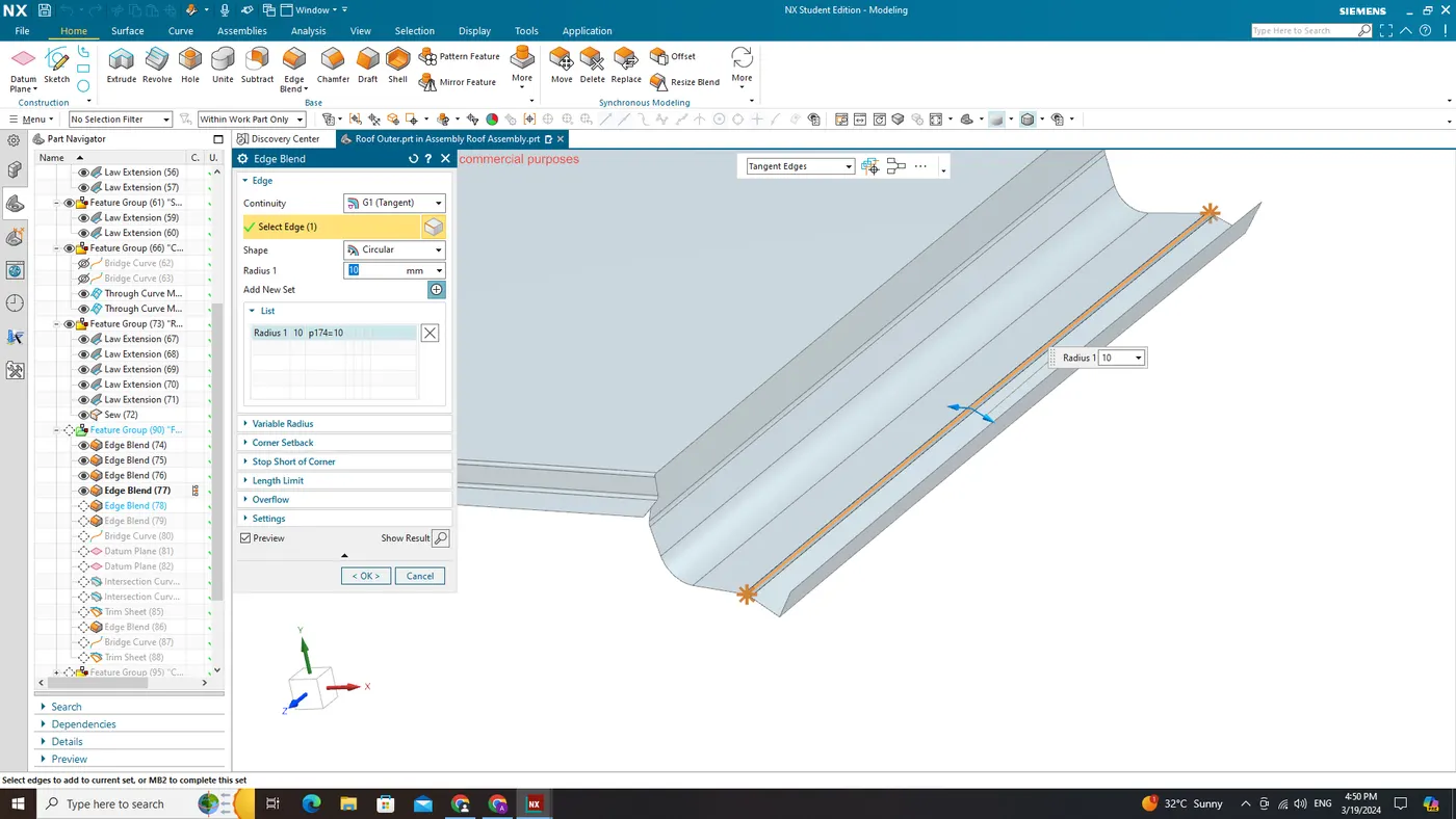
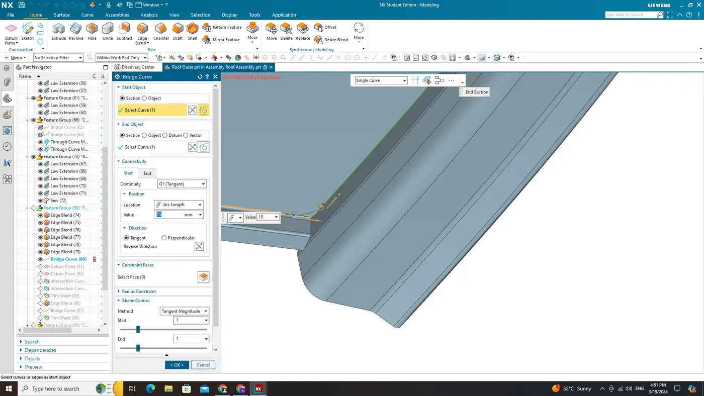
Start with the creation of a roof ditch area with a tool opening angle of 7 degrees.
Develop the reinforcements as separate parts
Bow–Roof Prediction Formula
W = [1.73 x 10^(-3) x L] + [1.85 x 10^(-8) x (R^2)/t] + [ 1.10x10^(-3) x l] - 2.68
Where,
L = Roof Length in X-Direction[mm](Roof dimension in 0-Y)
R = Roof curvature
R = 2(Rx*Ry)/(Rx+Ry)
Rx = X curvature
Ry = Y curvature
t = Roof plate thickness [mm]
l = Bow Roof Span [mm]
Judgment Condition
OK< 2.7
Snow Load Prediction Formula
Qr = [Iy x t2] / [α x s x [(Rx + Ry)/2]2 x 10-8]
Note: The Qr value given over here is correct. There was a typo error in the formula given in the video.
Where,
α = My x Lx2 x 10-12 , My = Y(Ly-Y)
t = Roof plate thickness [mm]
Ly = Distance between the front and rear roof Rails on the Vehicle along with 0Y[mm]
Length of Roof panel with the center point between Roof rail Front /Rear as the front and rear reference point.
Lx = Distance between the Left and Right end of the roof on the Roof BOW [mm]
The width of the roof panel is exposed on the surface.
Y = Distance front Front Roof Rail to Roof BOW[mm]
s = Distance for which Roof BOW bears divided load [mm]
s = L1/2 + L2/2
Iy = Geometrical moment of inertia of Roof BOW (Y cross-section )[mm4]
Rx = Lateral direction curvature radius of roof panel Y cross-section on Roof BOW [mm]
Roof panel curvature Radius of the Length Lx in Front view
Ry = Longitudinal Direction curvature radius of the Roof panel X cross-section on Roof BOW [mm]
Roof panel X curvature radius of length s in Side view
Judgment condition
Qr ≥ 3.1
250 ≤ s ≤ 380
Here are some Reference images for the Master sections - These images are just to give you a brief idea about the design.
Front Roof Rail Master section
Master section of the Rear Roof Rail
Master section of Bow Roof
Master section of Center Reinforcement Rail
The purpose of this report is to examine and formulate the design for the external roof structure of a car, utilizing a provided styling surface or Class A Surface. The primary focus is on creating a comprehensive assembly for the outer roof, specifically addressing the ditch area and incorporating necessary reinforcements in the form of five bow roofs.
The reinforcement design comprises Front and Rear Bow Roofs, a Bow Roof positioned after the Front Roof (referred to as "Bow Roof One"), a Central Bow Roof with an additional reinforcement roof beneath it (if a sunroof is present), and another bow roof situated between the Central Bow Roof and Rear Bow Roof (referred to as "Bow Roof Two"). These reinforcements are intended to enhance structural integrity, ensuring optimal performance under varying loading conditions.
To ensure precision in results, this report will employ pre-defined Master Sections provided in advance for each respective bow roof. Consistent use of these sections throughout the design process guarantees compatibility and uniformity within the overall outer roof assembly.
Beyond the design of these bow roofs, the report aims to conduct comprehensive calculations for Heat Distortion and Snow Load Criteria for both the main outer roof structure and its corresponding reinforcements. By rigorously evaluating these critical factors, the report ensures compliance with industry standards for thermal stability under heat distortion scenarios and adequate load-bearing capacity in regions susceptible to heavy snowfall.
Special emphasis will be placed on incorporating an additional reinforcement roof directly beneath the Central Bow section when integrating a sunroof into the outer roof assembly. This supplementary reinforcement aims not only to enhance structural integrity but also to accommodate any necessary modifications related specifically to sunroof installation requirements.
Introduction:
The car roof, also known as the automobile roof or car top, is the section of a vehicle positioned above the passenger compartment. Its primary function is to shield vehicle occupants from external elements such as sun, wind, and rain. In the early days of automobile design, when cars were conceived in the era of horse-drawn carriages, the materials and designs employed for automobile roofs closely mirrored those used in their predecessor vehicles.
Types of roofs in car:
There are various types of roofs used in cars, each offering distinct features and styles. Here are some common types:
-
Hardtop Roof:
- Fixed Hardtop: A solid, non-removable roof.
- Retractable Hardtop: A roof that can be folded or retracted, often into the trunk, providing an open-air driving experience.
-
Soft Top Roof:
- Convertible Top: A fabric or vinyl roof that can be lowered or stowed to open up the car to the elements.
- Targa Top: A removable roof panel, typically over the front seats, leaving the rear portion of the roof intact.
-
Sunroof/Moonroof:
- Panoramic Sunroof: A large sunroof that extends over a significant portion of the roof, providing a wide opening.
- Pop-up Sunroof: A smaller sunroof that can be tilted open or fully retracted.
-
T-Top Roof:
- T-Top: Two removable roof panels over the front seats, forming a "T" shape when removed.
-
Convertible Roof:
- Traditional Convertible: A car with a roof that can be fully folded down, usually made of fabric or vinyl.
- Roadster: A convertible with two seats and minimal or no weather protection.
-
Fixed Roof:
- Coupe: A fixed roof with two doors and a sloping rear, often providing a sportier look.
- Sedan: A fixed roof with four doors, providing ample passenger space.
-
Cabriolet:
- A term often used interchangeably with convertible, especially in European markets.
-
Hatchback Roof:
- Hatchback: A roof design that includes a rear door with a rear window that swings upward.
-
SUV and Crossover Roofs:
- SUV Roof: Generally, a more upright and higher roof to accommodate the taller body style.
- Crossover Roof: Combines elements of an SUV and a car, often with a sleeker roofline than a traditional SUV.
-
Retractable Hard Roof (RHR):
- A high-end variation of the convertible top, where a hard roof panel retracts into the trunk.
These roof types contribute to the diversity in automotive design, allowing manufacturers to cater to various preferences and functional needs.
Heat Distortion Criteria:
Heat distortion criteria for a car roof refer to the standards and specifications set to ensure that the roof can withstand and maintain its structural integrity under elevated temperatures. The term "heat distortion" relates to the deformation or warping that may occur in materials when exposed to high temperatures. In the context of automotive roofs, it's crucial to establish criteria that prevent adverse effects such as distortion, sagging, or other structural compromises when the vehicle is exposed to heat, whether from external environmental conditions or internal sources like sunlight.
Key considerations for heat distortion criteria for car roofs include:
-
Material Selection: Choosing materials with high heat resistance is fundamental. Common materials used in automotive roofs, such as steel, aluminum, or composite materials, must be selected based on their ability to withstand elevated temperatures without significant deformation.
-
Testing Protocols: Establishing specific testing protocols and methodologies to simulate real-world conditions that may expose the car roof to high temperatures. This involves subjecting roof materials to controlled heat sources to evaluate their performance under various temperature scenarios.
-
Performance Standards: Defining specific standards and limits for acceptable heat distortion. This could involve setting maximum temperature thresholds or establishing criteria for allowable degrees of distortion under specific conditions.
-
Climate Considerations: Recognizing that different regions may experience varying temperature extremes, the heat distortion criteria should consider a range of environmental conditions to ensure the roof's performance in diverse climates.
-
Long-Term Durability: Ensuring that the heat distortion criteria account for the long-term durability of the roof material. Over time, repeated exposure to high temperatures can lead to cumulative effects on the structural integrity, making it essential to assess how well the material maintains its properties over the vehicle's lifespan.
-
Mitigation Strategies: Developing strategies to mitigate heat-related issues, such as incorporating insulation materials or reflective coatings to minimize heat absorption and transfer to the roof structure.
Compliance with heat distortion criteria is vital for ensuring the safety, functionality, and aesthetics of the vehicle, especially in regions with high ambient temperatures. Manufacturers typically conduct rigorous testing and analysis to meet or exceed these criteria, adhering to industry standards and regulations to guarantee the car roof's performance and longevity under various thermal conditions.
Snow Load Criteria:
Snow load criteria for a car roof involve the establishment of standards and specifications to ensure the roof can withstand the weight and pressure exerted by accumulated snow. These criteria are crucial in regions where heavy snowfall is common, as an overloaded roof can pose safety risks and compromise the structural integrity of the vehicle. The objective is to design and construct car roofs that can effectively support the additional load imposed by snow, preventing deformation, collapse, or other adverse effects.
Key considerations for snow load criteria for car roofs include:
-
Snow Density: Different types of snow have varying densities, affecting the overall load. Wet, heavy snow weighs more than dry, powdery snow. Snow load criteria should consider these variations to account for different real-world scenarios.
-
Geographic Location: Recognizing that snowfall patterns differ by geographic location, the criteria should be region-specific. Areas with heavy and frequent snowfall will require higher snow load resistance compared to regions with milder winter conditions.
-
Building Codes and Standards: Adhering to local building codes and industry standards that specify the acceptable snow loads for structures. These standards may be set by national or regional authorities and are designed to ensure the safety and reliability of roofs in snow-prone areas.
-
Roof Design and Pitch: The design of the car roof, including its slope or pitch, can influence how snow accumulates and sheds. Criteria should consider these design factors to optimize load distribution and prevent excessive snow buildup.
-
Material Strength: Ensuring that the materials used in the construction of the roof, whether steel, aluminum, or composite materials, have sufficient strength to bear the additional weight imposed by snow accumulation.
-
Snow Removal Considerations: In some cases, the snow load criteria may also consider the feasibility and safety of manually removing accumulated snow from the roof, especially for vehicles parked outdoors.
-
Testing and Certification: Establishing testing protocols to evaluate the performance of car roofs under simulated snow load conditions. Certification processes may be in place to ensure that vehicles meet or exceed the prescribed snow load criteria.
-
Dynamic Load Considerations: Recognizing that dynamic factors, such as the impact of sliding or shifting snow, should be considered in addition to static snow loads to ensure comprehensive safety assessments.
By implementing and adhering to snow load criteria, manufacturers can design and produce car roofs that are resilient and safe under winter conditions. Compliance with these criteria is essential for ensuring the overall safety and durability of vehicles in regions prone to significant snowfall.
Use of Automotive Roof:
The automotive roof serves several essential functions, contributing to both the safety and comfort of vehicle occupants. Here are key uses of automotive roofs:
- Occupant Protection: The primary purpose of an automotive roof is to provide a protective enclosure for vehicle occupants. In the event of a rollover or other accidents, the roof acts as a crucial barrier, preventing the occupants from being crushed or ejected.
-
Weather Protection: The roof shields occupants from external elements such as rain, snow, hail, and intense sunlight. It helps maintain a comfortable and secure environment within the vehicle, regardless of weather conditions.
-
Structural Integrity: The roof plays a vital role in maintaining the overall structural integrity of the vehicle. It adds rigidity to the car's body, contributing to crashworthiness by distributing impact forces more evenly throughout the structure.
-
Rollover Prevention: Well-designed roofs contribute to preventing deformation and collapse during rollover accidents. This is essential for reducing the risk of injuries caused by impacts on objects outside the vehicle or internal components within it.
-
Roof Crush Resistance: In situations where a vehicle experiences significant vertical impacts, a strong and robust roof structure resists collapsing. This resistance is critical in preventing serious harm to occupants inside, especially when external objects press down on the car's roof surface.
-
Side Impact Protection: While not directly related to roofs themselves, the intact and sturdy nature of the roof is pivotal for the effective deployment of safety systems like side curtain airbags during side collisions, providing additional protection against head injuries.
-
Design Aesthetics: Beyond safety considerations, automotive roofs contribute significantly to the overall design aesthetics of the vehicle. Different roof styles, such as hardtops, soft tops, or panoramic roofs, add character to the vehicle's exterior.
-
Headroom and Cabin Space: The design of the roof also influences the interior space of the vehicle. In vehicles like SUVs and minivans, roofs are designed to provide ample headroom for passengers.
-
Energy Efficiency: The design of automotive roofs can impact the vehicle's energy efficiency. Smooth contours and well-designed roofs help reduce aerodynamic drag, contributing to improved fuel efficiency and reduced emissions.
-
Noise Reduction: Well-designed roofs with appropriate insulation materials help reduce noise levels from wind, rain, or road disturbances. This contributes to a quieter and more comfortable driving experience for occupants.
-
Sunroof Options: While not directly related to safety, the inclusion of sunroofs provides an additional feature that enhances the cabin ambiance by allowing natural light into the vehicle and offering a sense of openness for occupants.
In summary, the automotive roof serves a multifaceted role, encompassing safety, structural integrity, weather protection, design aesthetics, and various comfort features. Manufacturers carefully design and engineer roofs to meet safety standards and regulations while providing an enjoyable and secure driving experience for occupants.
Components of Roofs:
Automotive roofs are reinforced with various components to enhance structural integrity, safety, and performance. Different types of reinforcements found in a car roof include:
- Bow Roof:
Bow roofs serve as supplemental reinforcements applied to the flattest section of the roof, enhancing both its strength and load-bearing capacity. The quantity of bow roofs is contingent on the length of the roof; longer roofs necessitate a greater number of bow roofs for optimal structural support.
- Front Bow Roof:
A structural reinforcement located at the front section of the roof, providing support and stability.
- Rear Bow Roof:
Similar to the front bow, the rear bow roof is located at the rear section of the roof, contributing to overall structural strength.
- Central Bow Roof:
Positioned at the center of the roof, this reinforcement adds rigidity and support to the roof structure.
Joining Process:
In the central section of the roof, the outer roof panel and reinforcement roofs are connected through the introduction of mastic, which serves as a sealing and bonding agent. Mastic, a versatile form of sealant and adhesive, is strategically applied to fill joints and act as a robust bond between different materials. Its elastic and flexible properties make it an ideal choice for establishing a durable connection, ensuring the structural integrity of the roof assembly. Furthermore, to reinforce this connection, spot welding is employed at the conclusion of the joining process. Spot welding involves the localized fusion of metal surfaces, adding an extra layer of strength to the roof assembly and contributing to its overall stability.
Manufacturing Process:
Roofs undergo a manufacturing process known as stamping, wherein flat sheet metal, provided in either blank or coil form, is placed into a stamping press. In this process, a tool and die surface shape the metal into a net form. Stamping encompasses various sheet-metal forming manufacturing techniques, including punching using a machine press or stamping press, along with processes like blanking, embossing, bending, flanging, and coining. This procedure can be a single-stage operation, achieving the desired form with each stroke of the press, or it can involve a series of stages. While the process is typically applied to sheet metal, it can also be utilized on alternative materials such as polystyrene.
1 – Blanking and Punching 2 – Deep drawing 5 – Spot Welding
3 – Hemming 4 – Gluing (Mastic and Hemming glue)
Blanking – Cutting of the Sheet metal along a closed Outline in a single step to separate the piece from the surrounding stock.
Deep drawing – It is the sheet metal forming process in which a sheet metal blank is radially drawn into a forming die by the mechanical action of a punch. The process is considered deep drawing when exceeds its diameter.
Advantage
1- Manufacture the products more quickly and higher quality.
2- More effective and efficient.
Hemming – Hemming is a sheet metal forming process in which sheets are joined by bending over another part in order to achieve a tight fit.
Advantage
1- Connects two sheet metal part together.
2- Improve the appearance of a part and reinforce part edges.
Gluing (Mastic) – todays we use gluing for sheet metal joining. Best example Roof reinforcements and styling surface joining by Hemming glue, in hemming we use hemming glue for stability and for strong bonding between roof reinforcement and styling surface.
Spot Welding - Spot weld is used for joining front roof rail with the roof flange, and also use to joining the rear roof rail with the rear roof flange.
Corner Relief - Basically, at the sheet metal operations like (deep drawing and bending, blanking) mostly at the corners stress or strain concentration occurs so that’s we give some relief to the corners for removing these stress and strain.
Design Consideration for Roof:
- Visibility criteria
- Head clearance
- Curvature study
- Heat distortion and snow load criteria
- Draft analysis
Model:
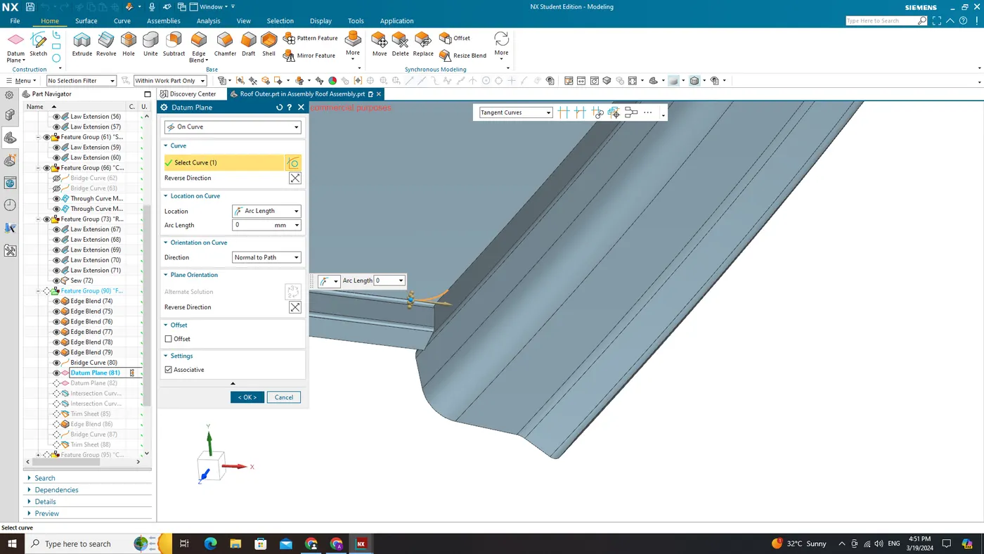
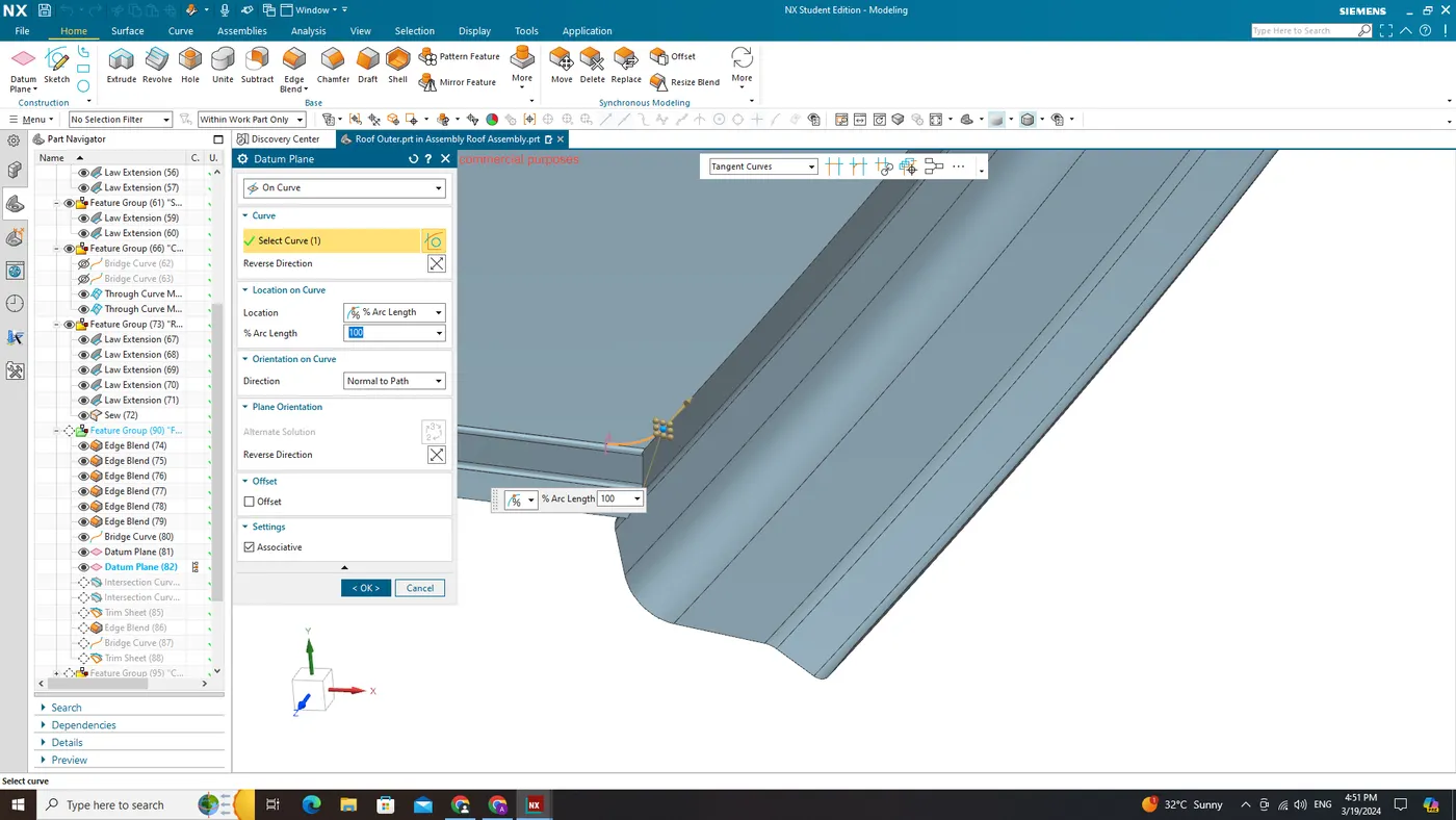
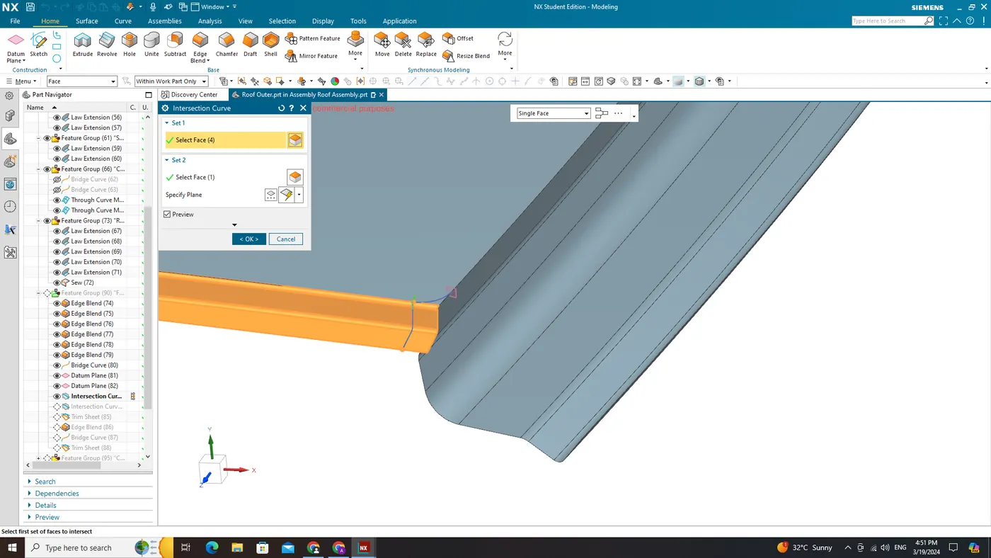
Skin Data
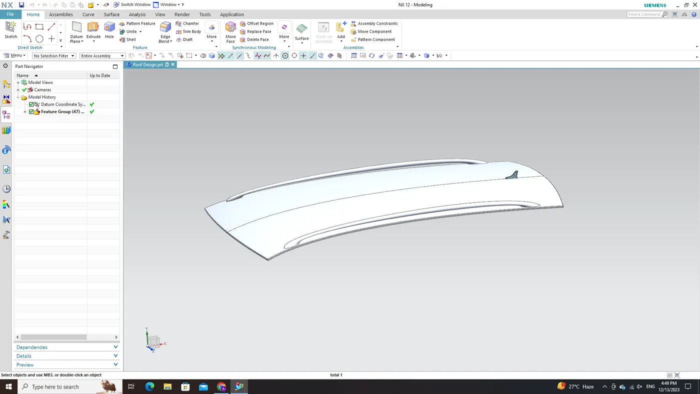
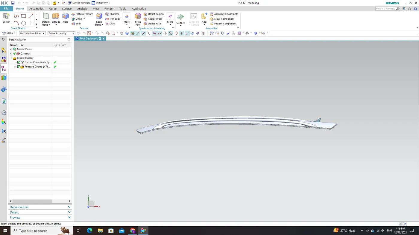
Roof Outer Panel
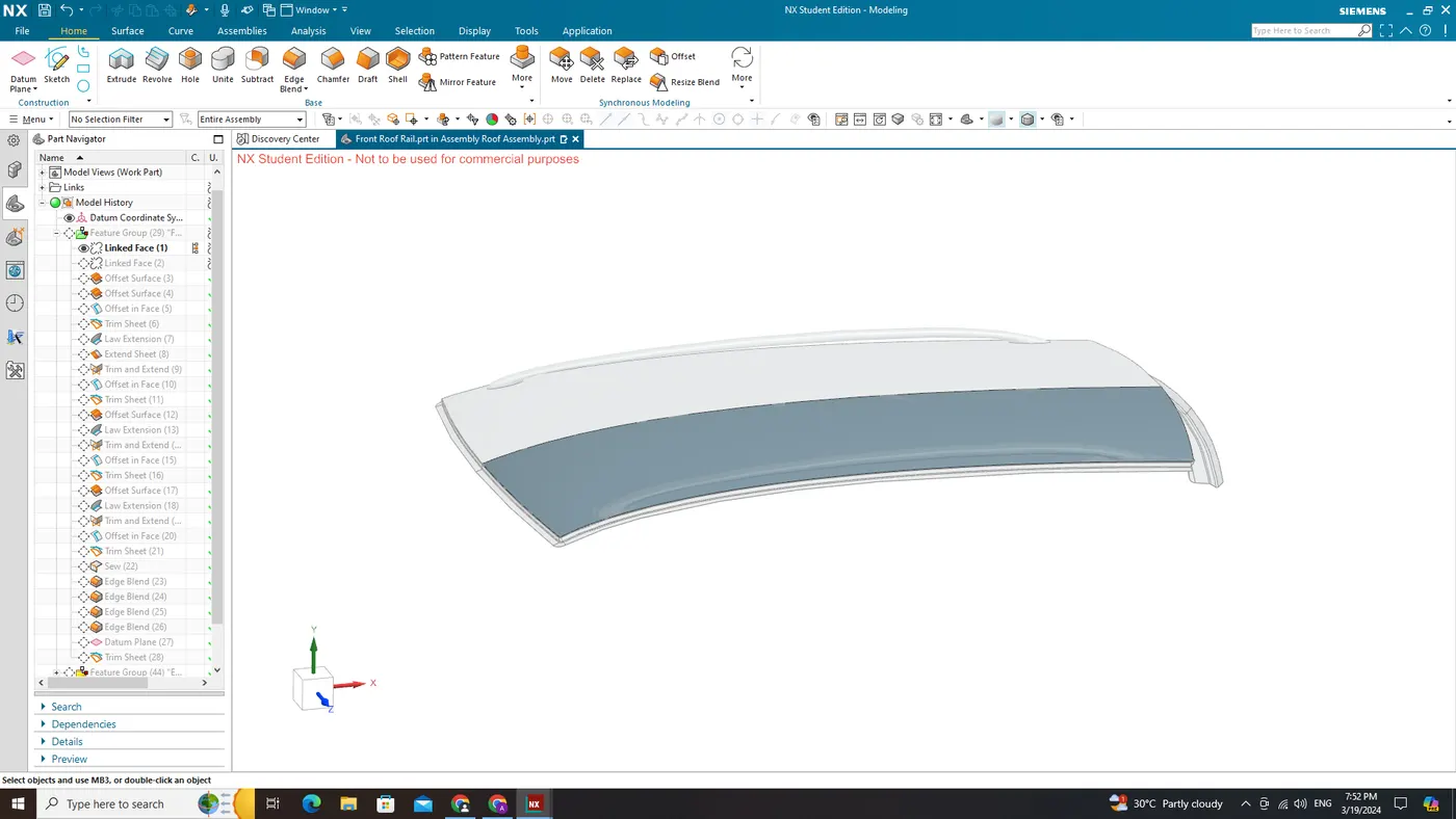
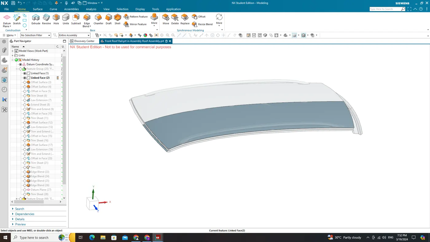
Extracted Face
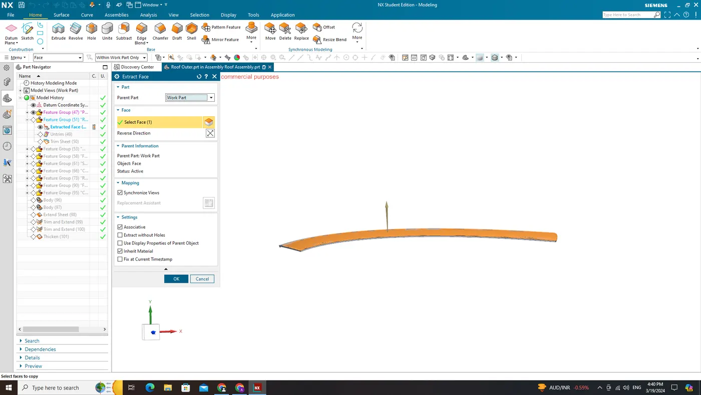
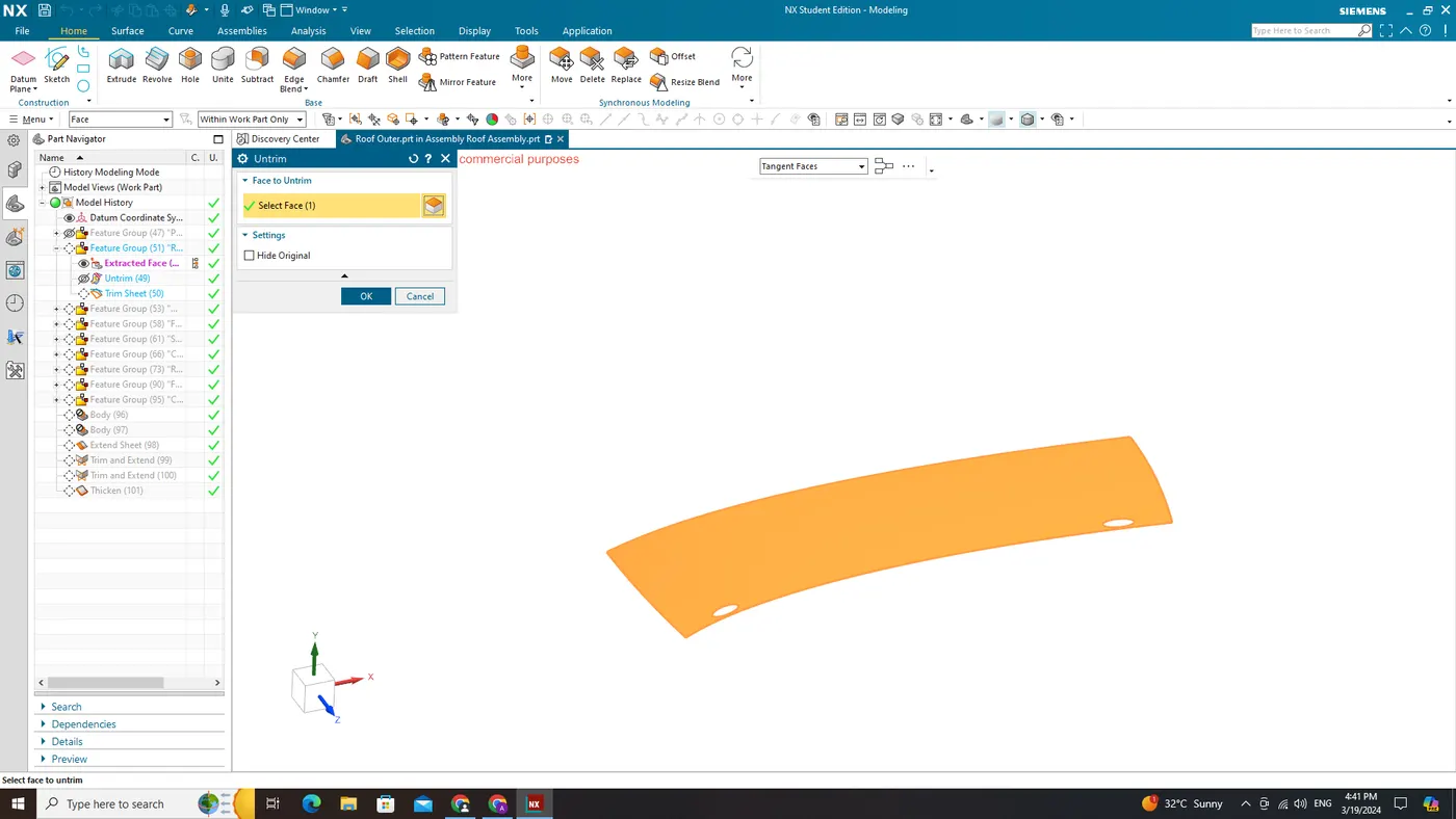
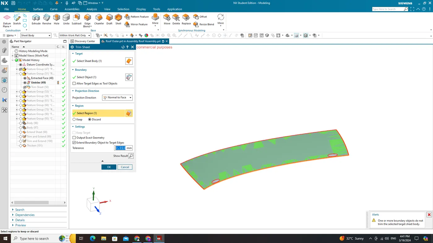
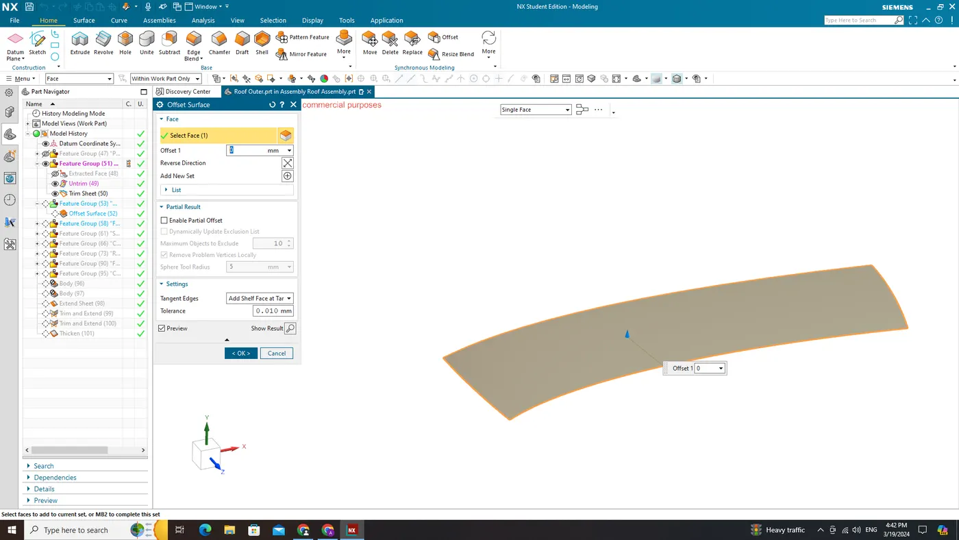
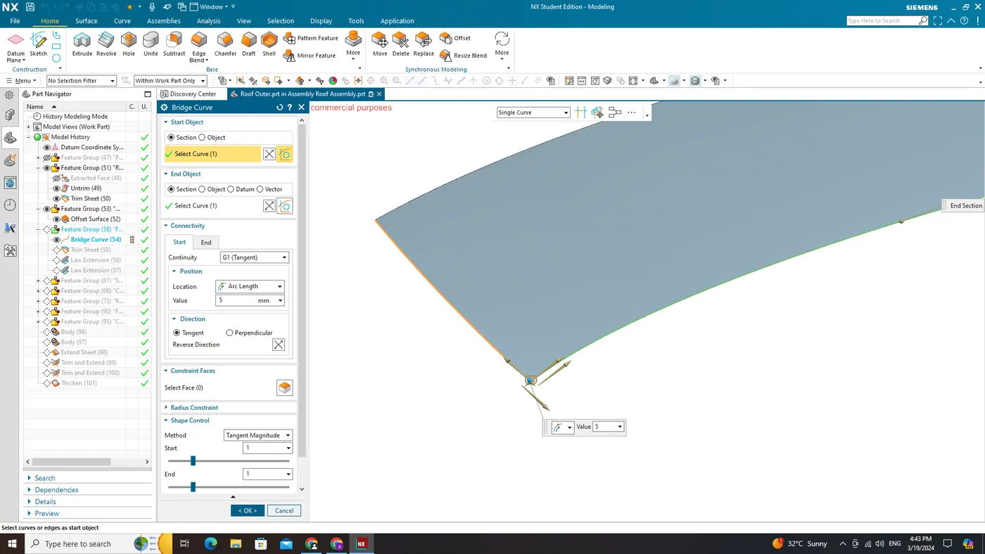
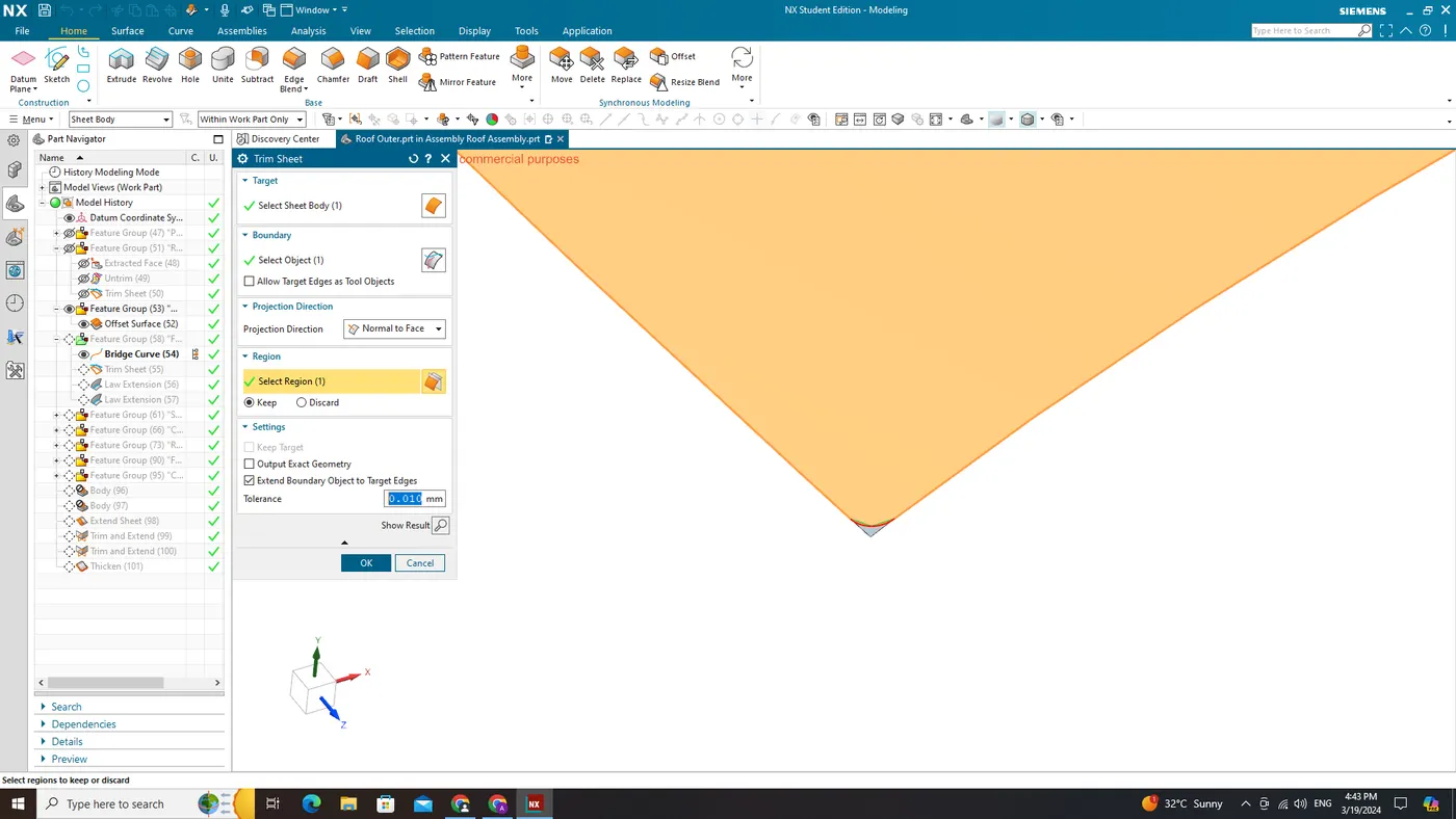
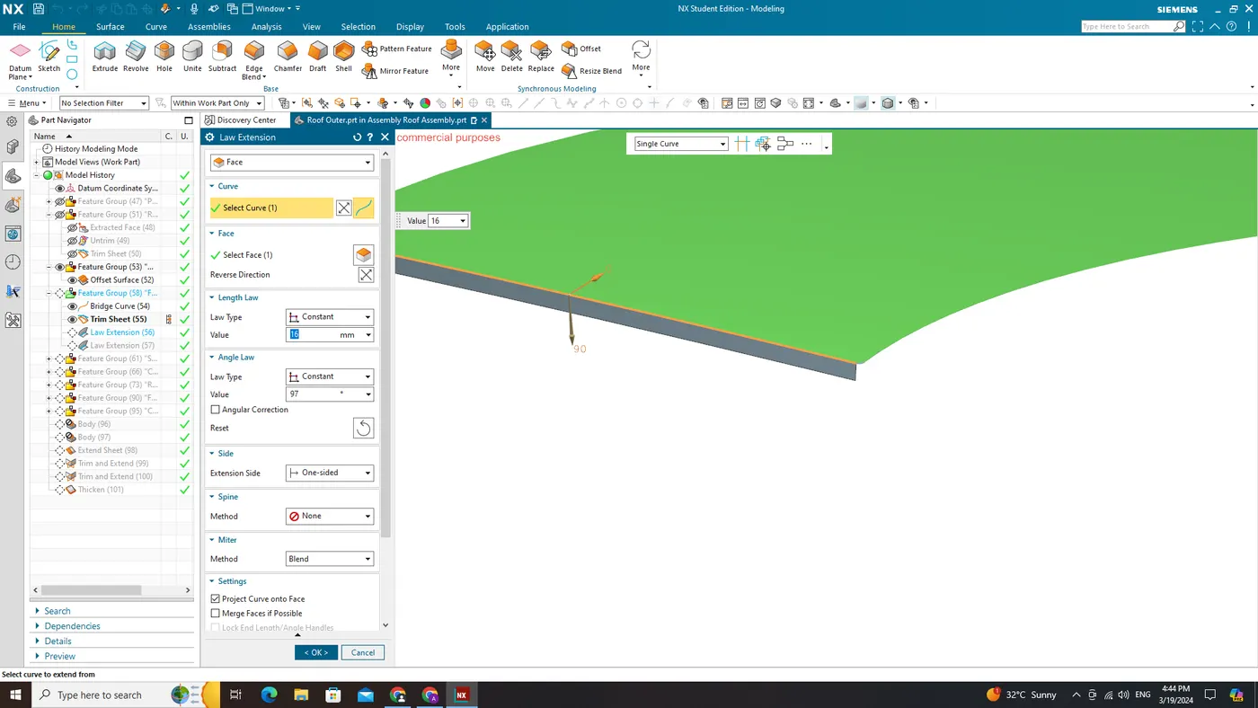
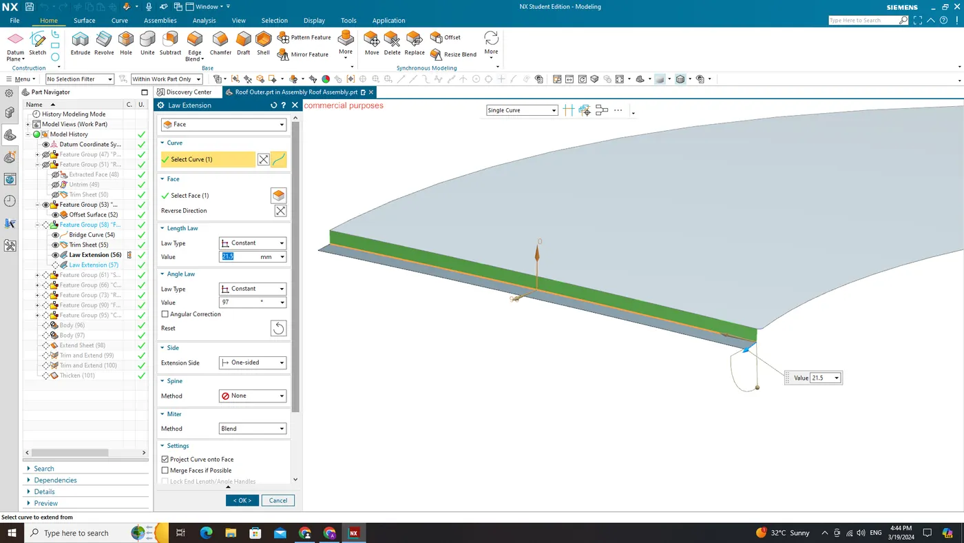
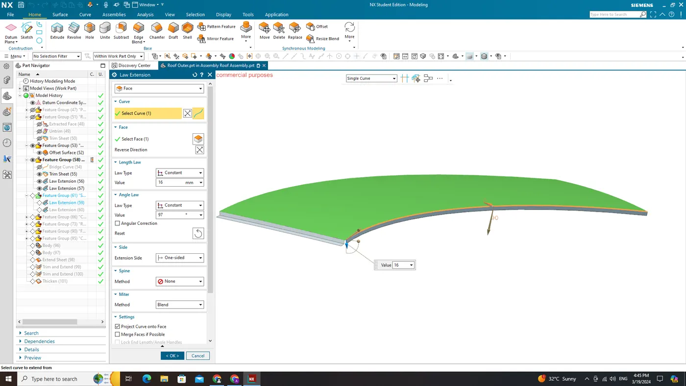
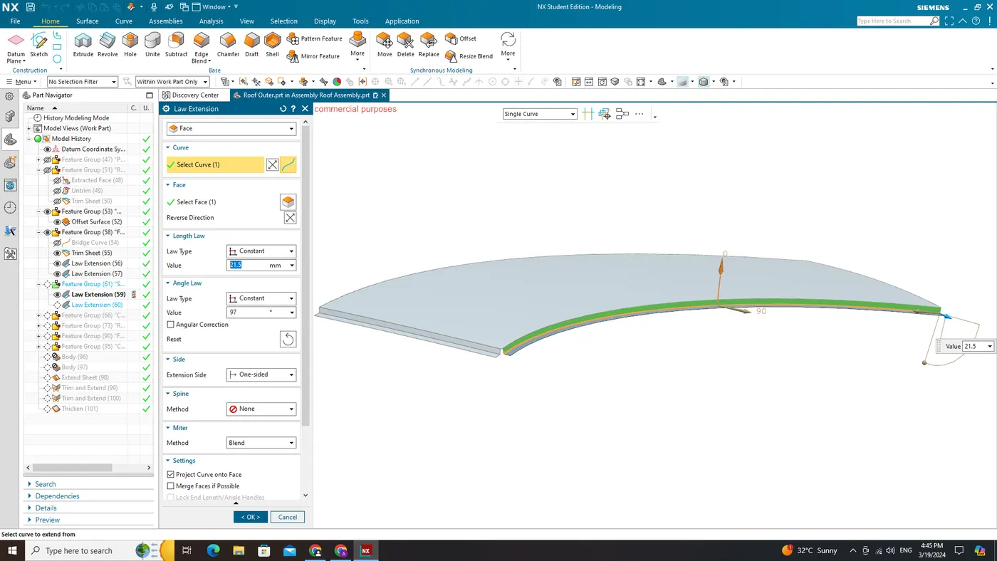
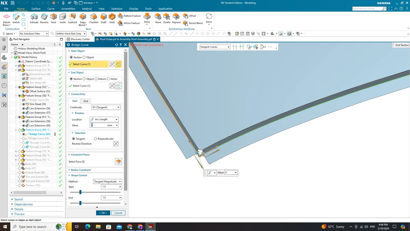
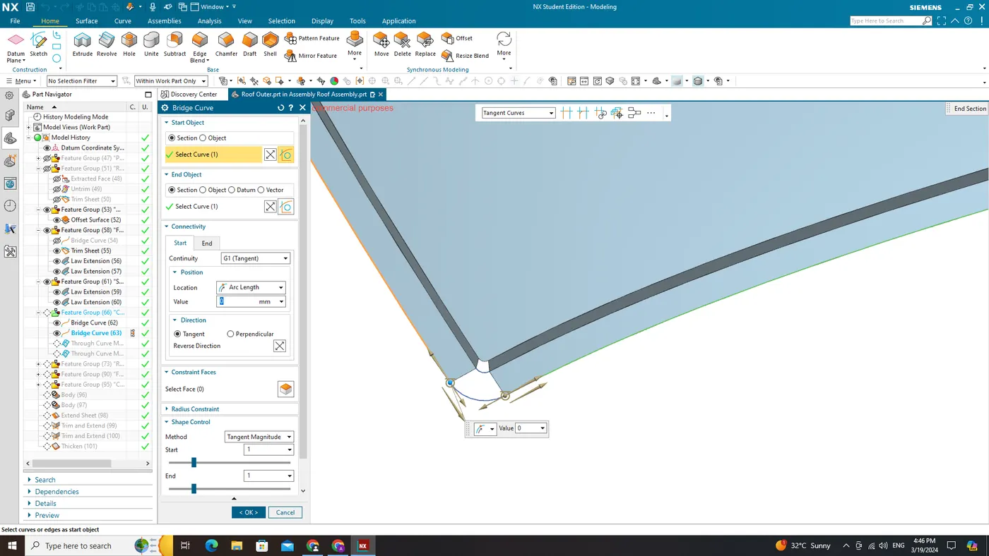
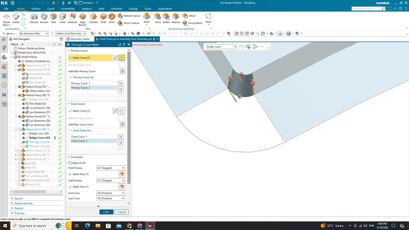
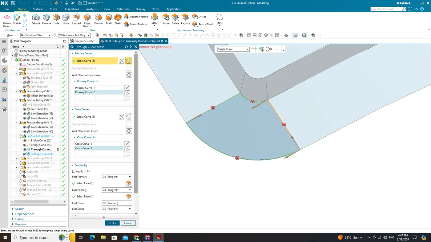
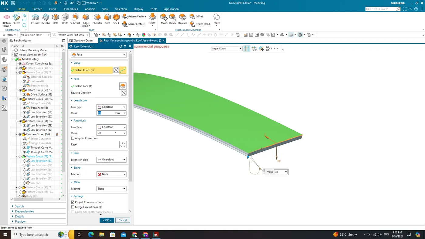
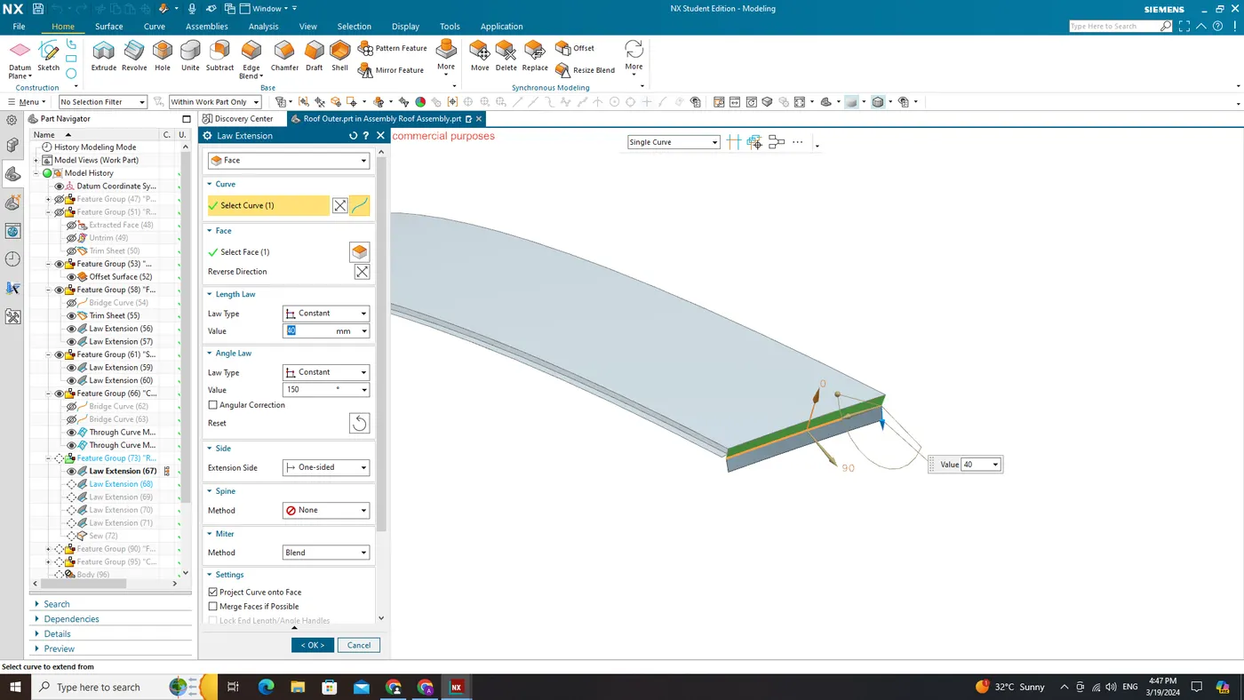
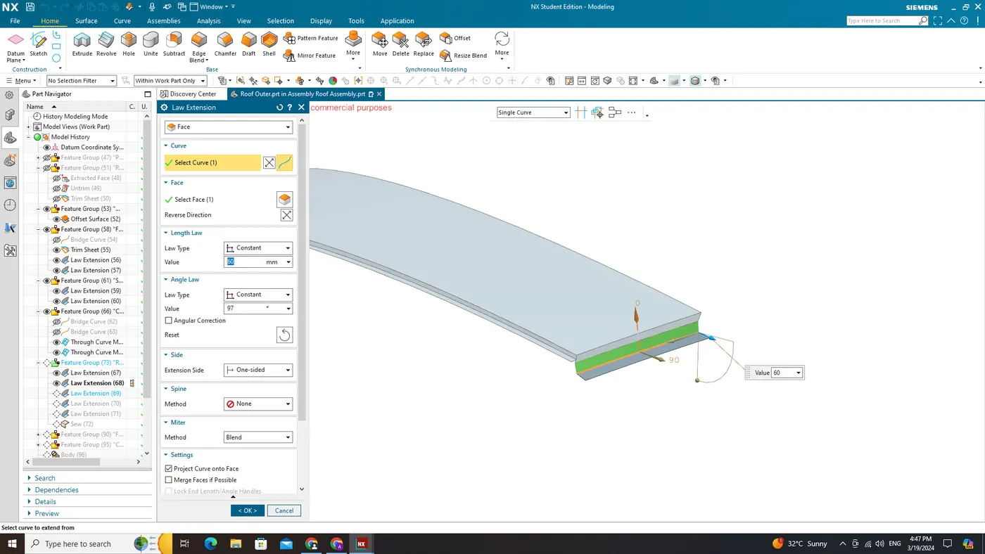
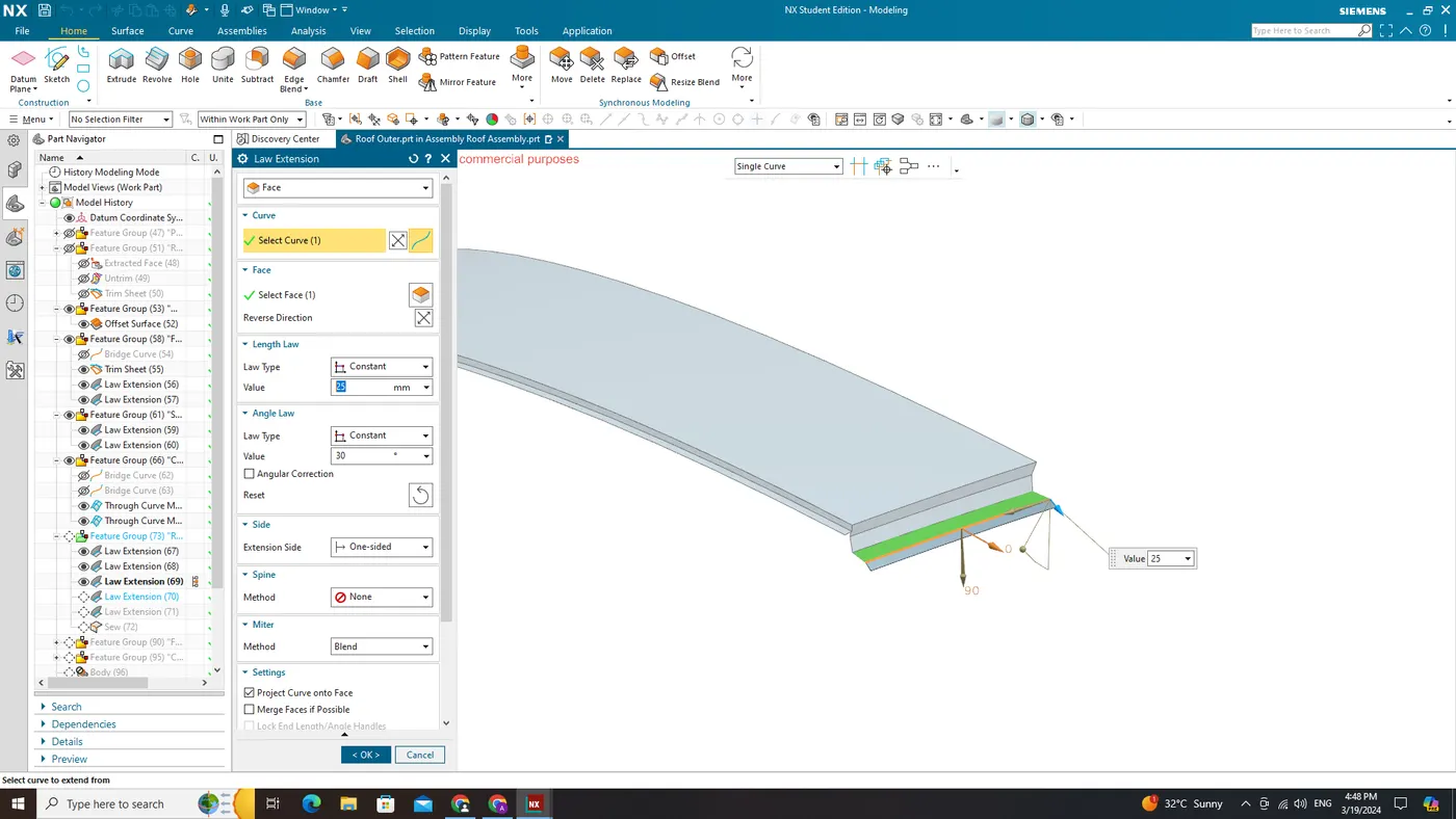
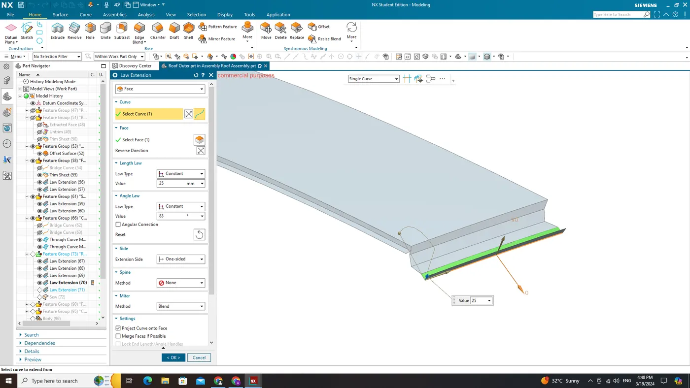
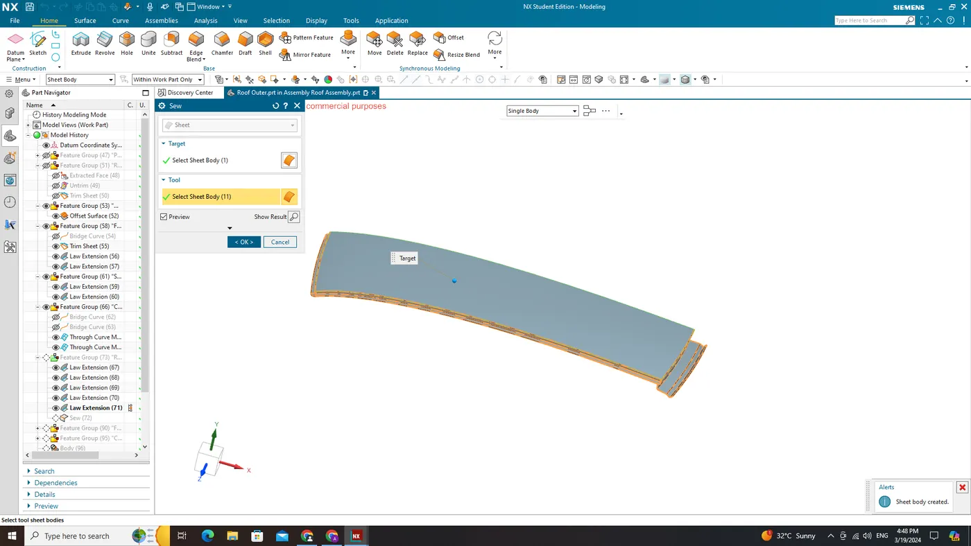
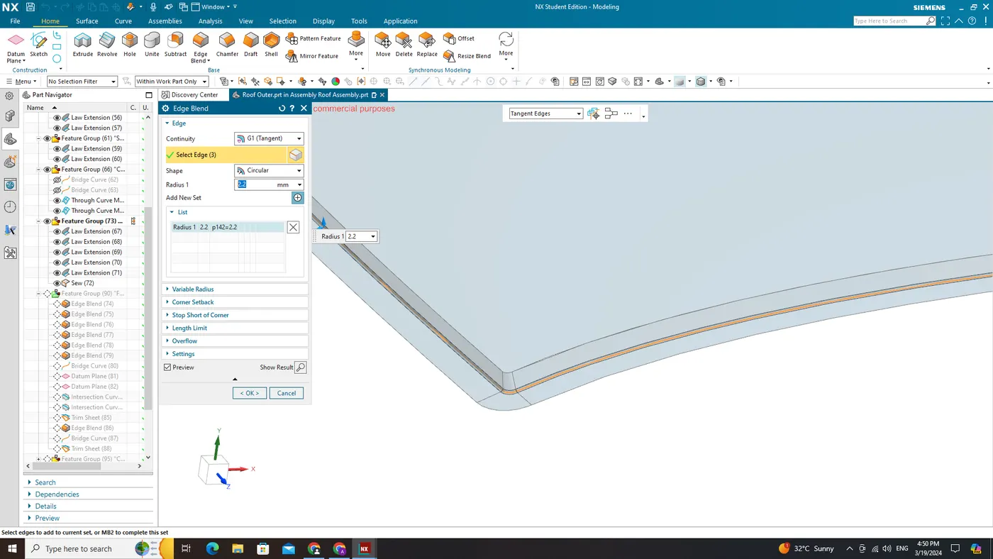
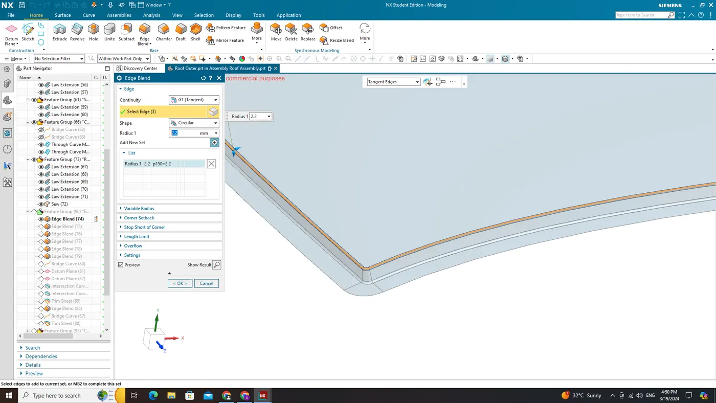
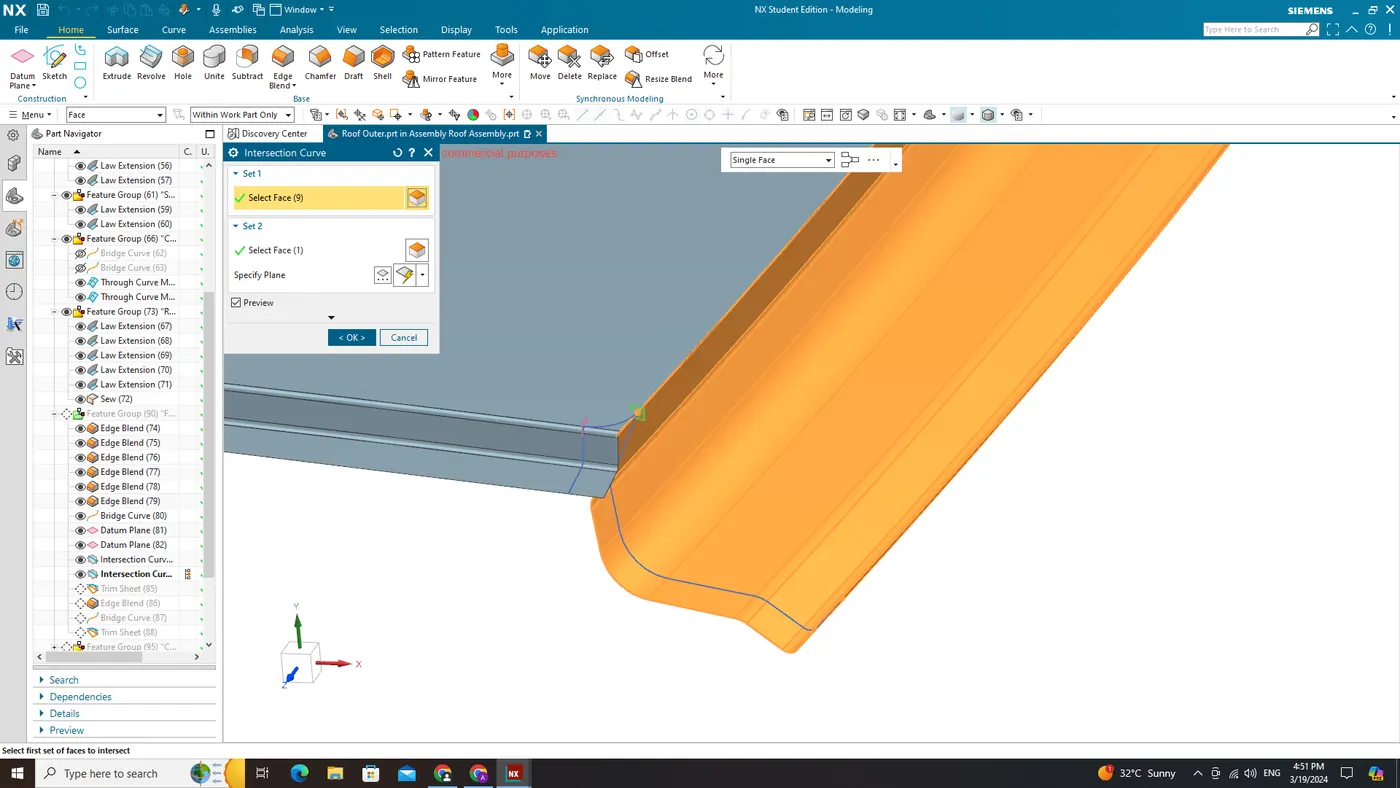
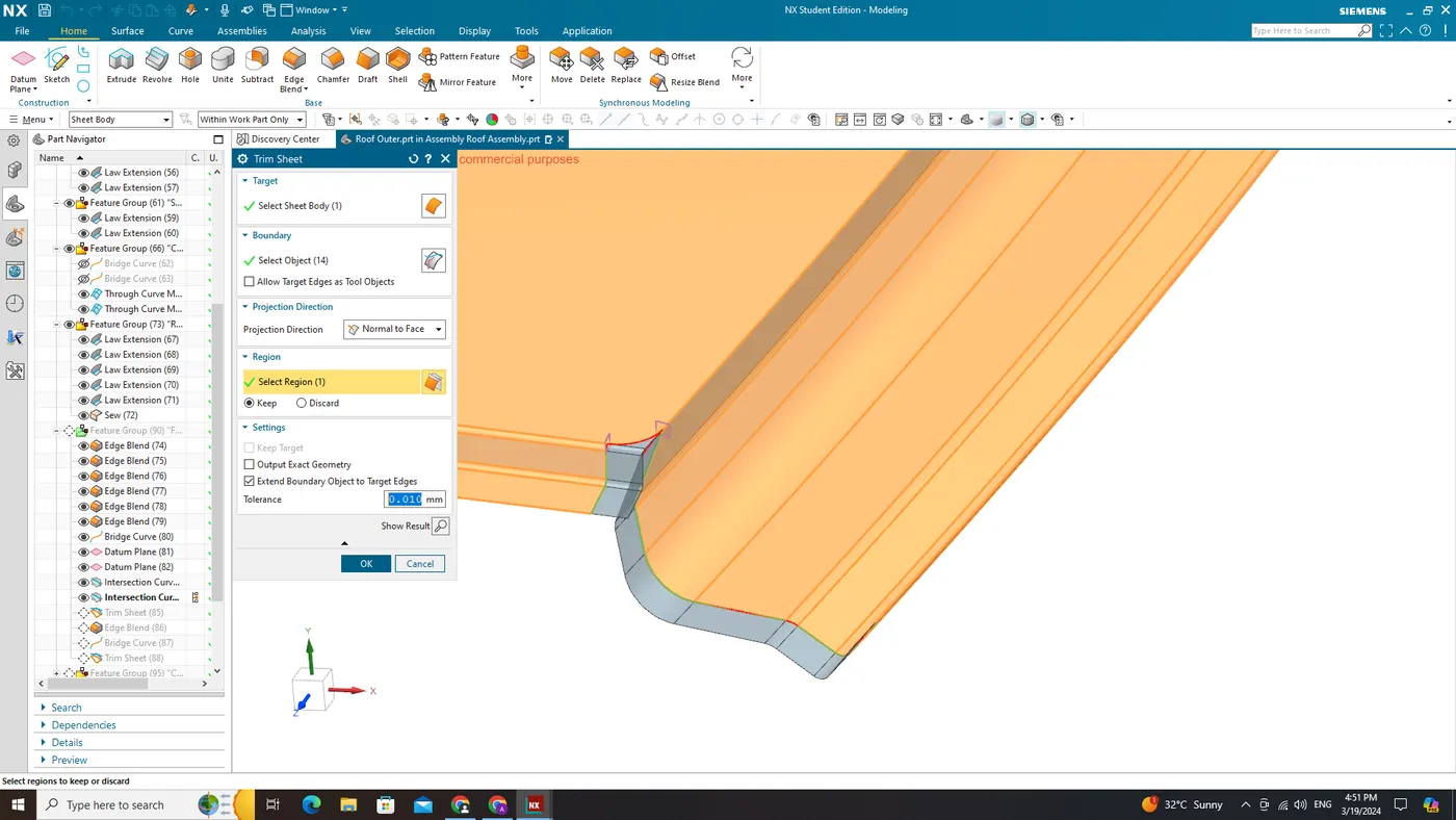
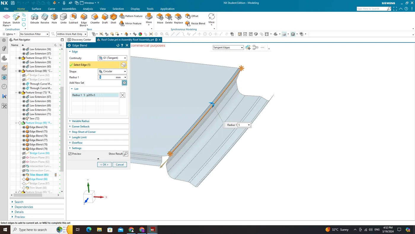
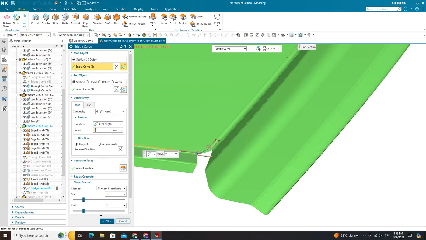
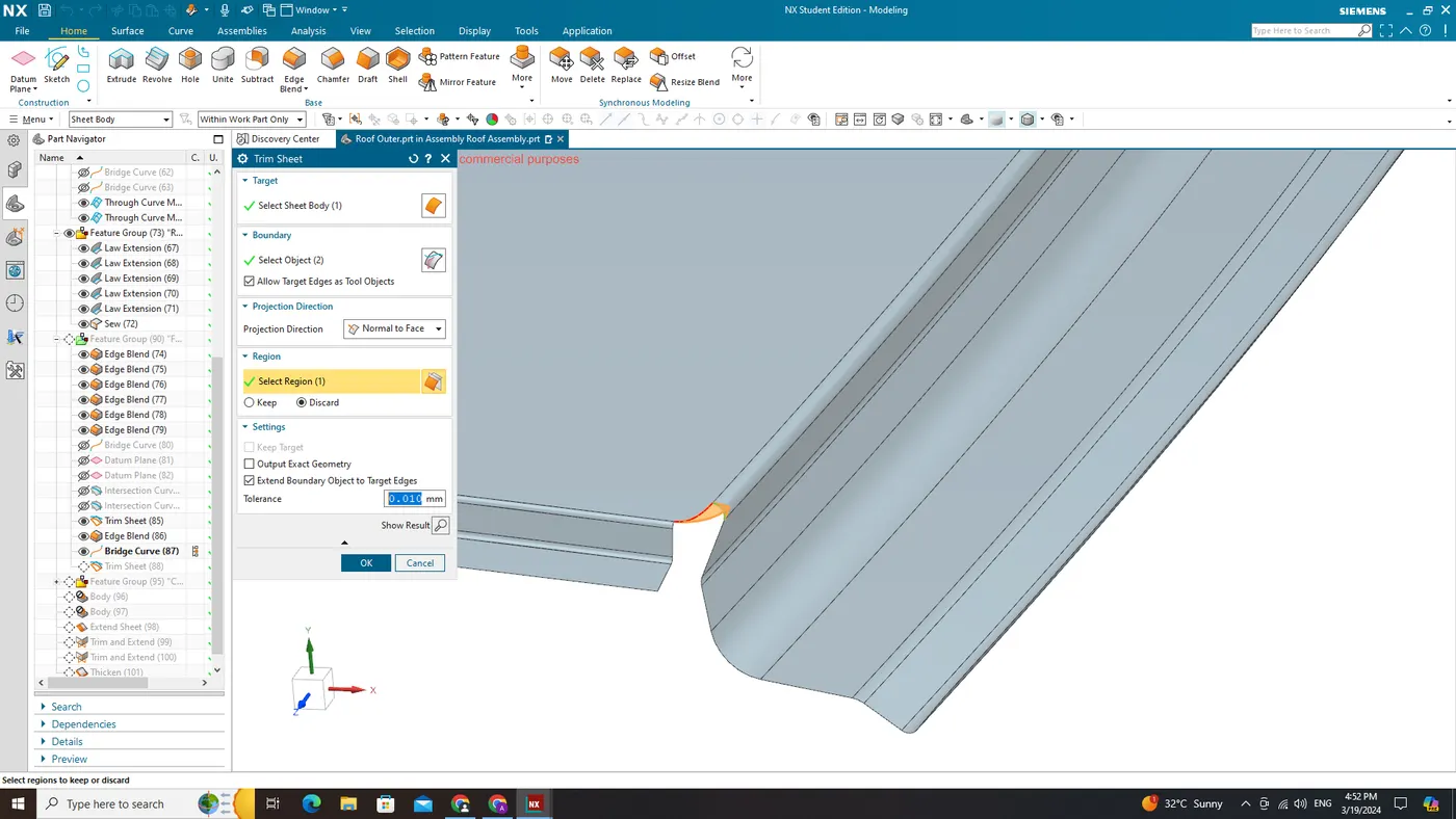
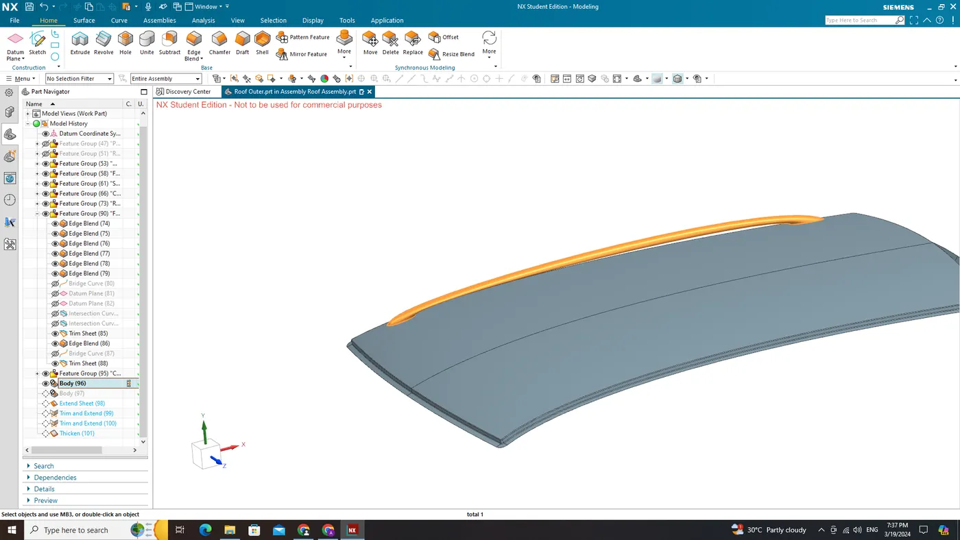
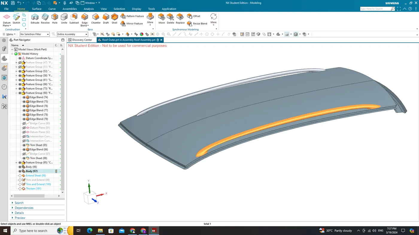
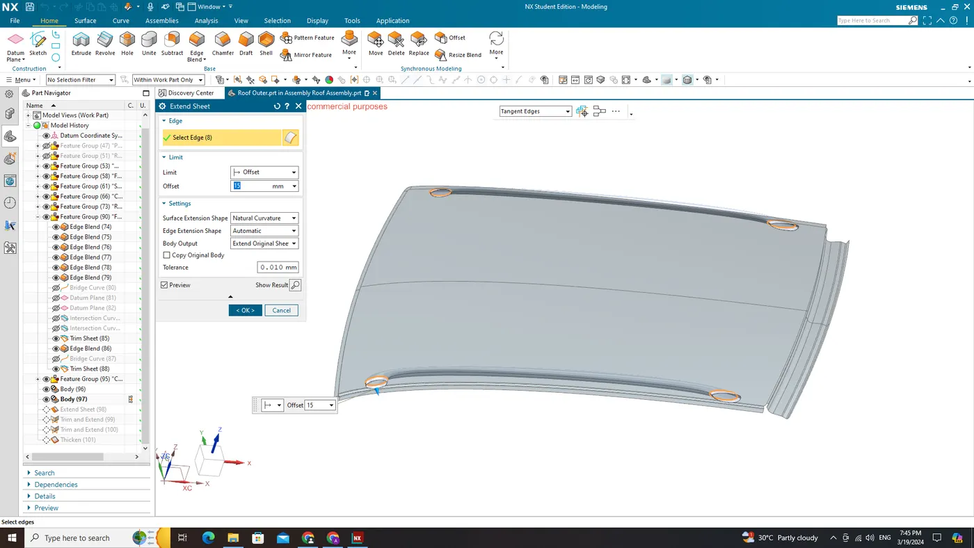
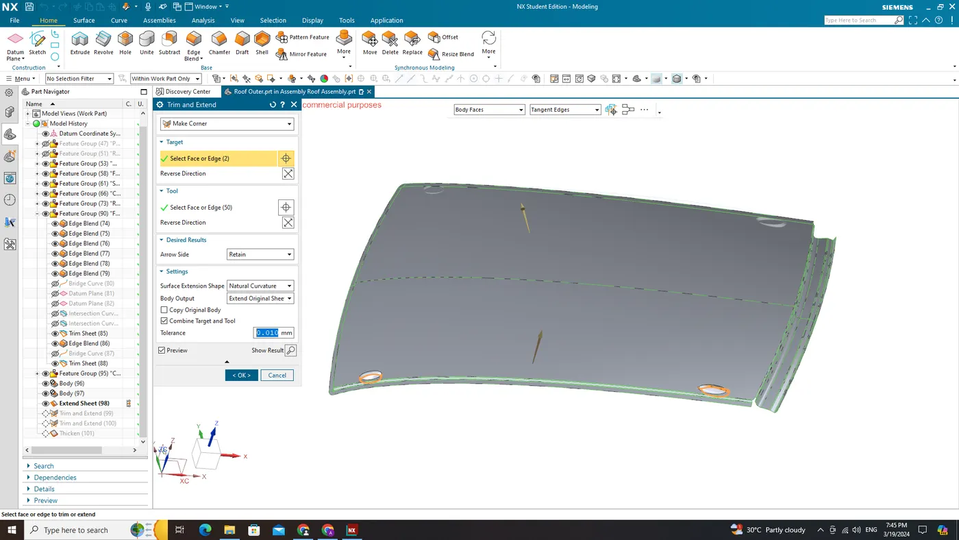
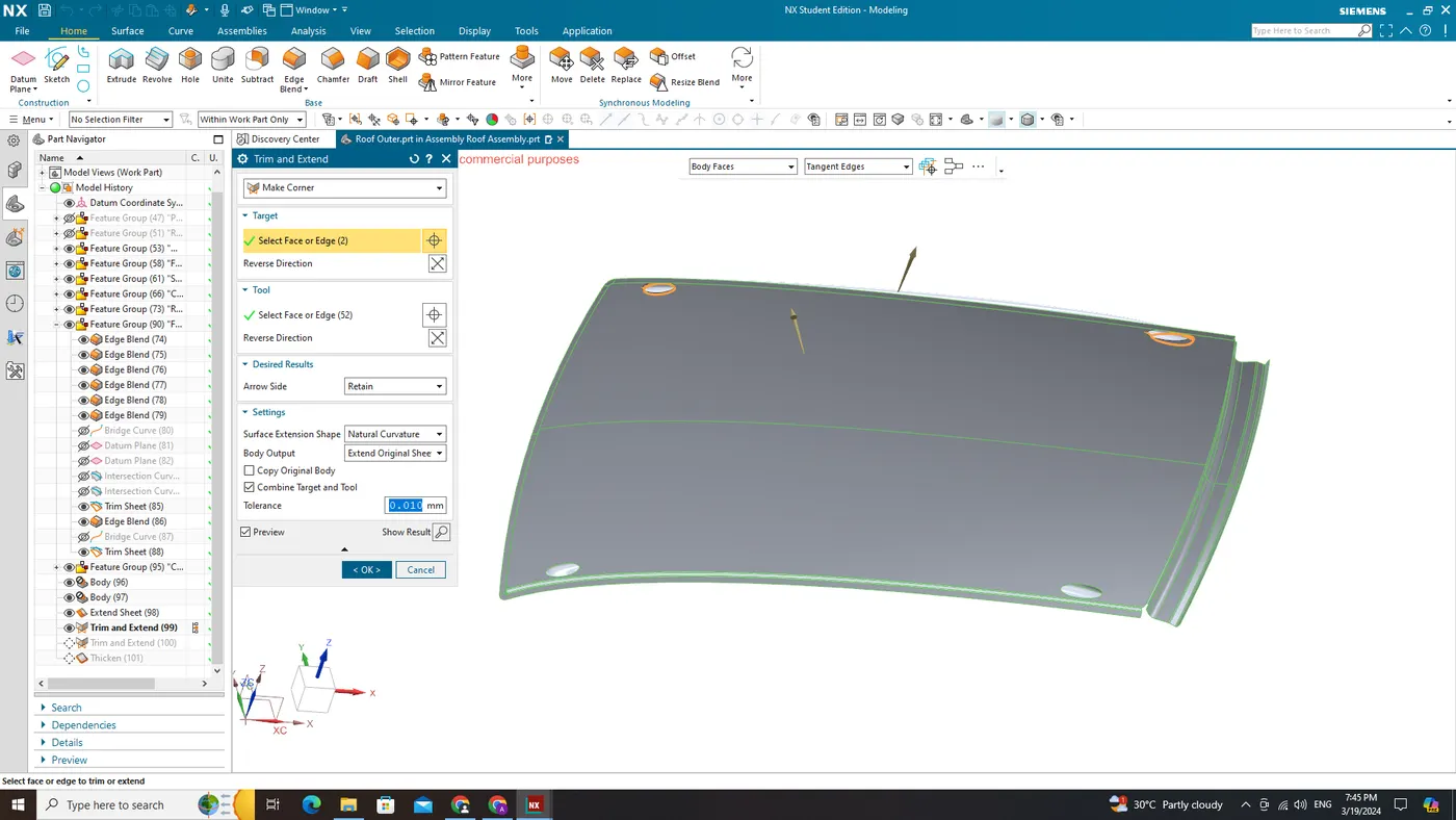

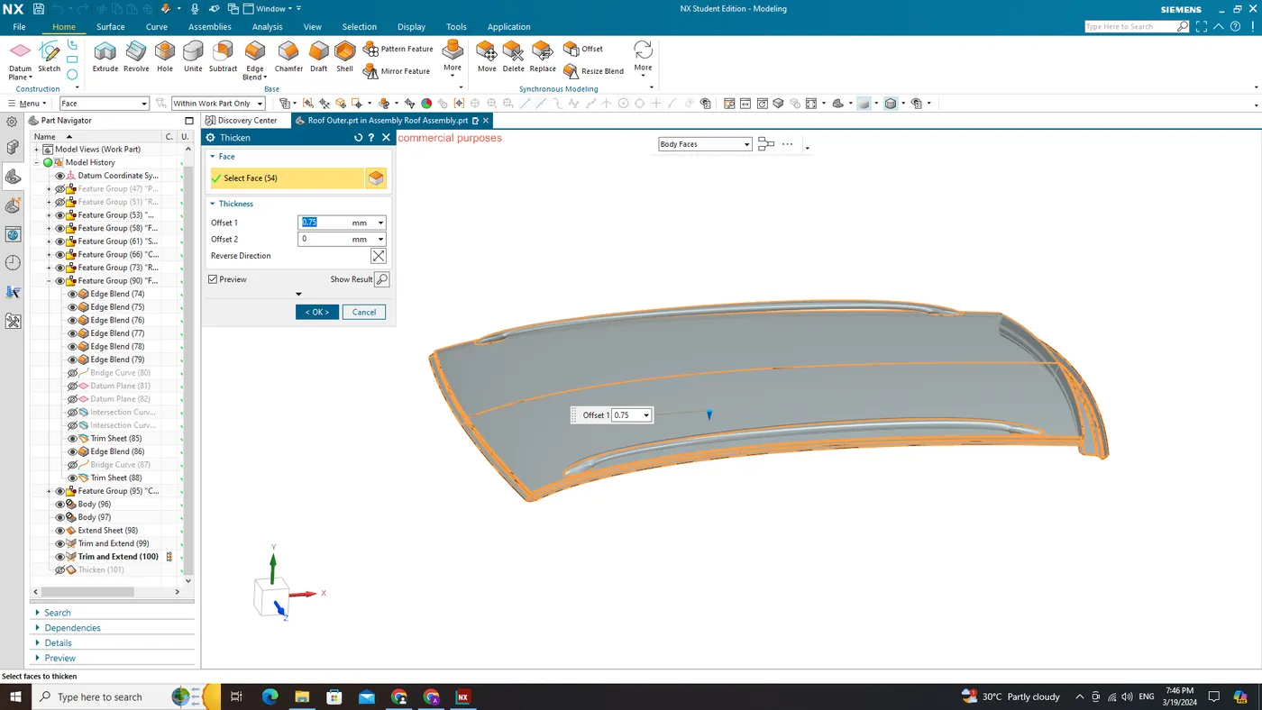
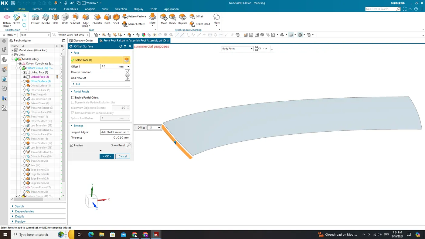
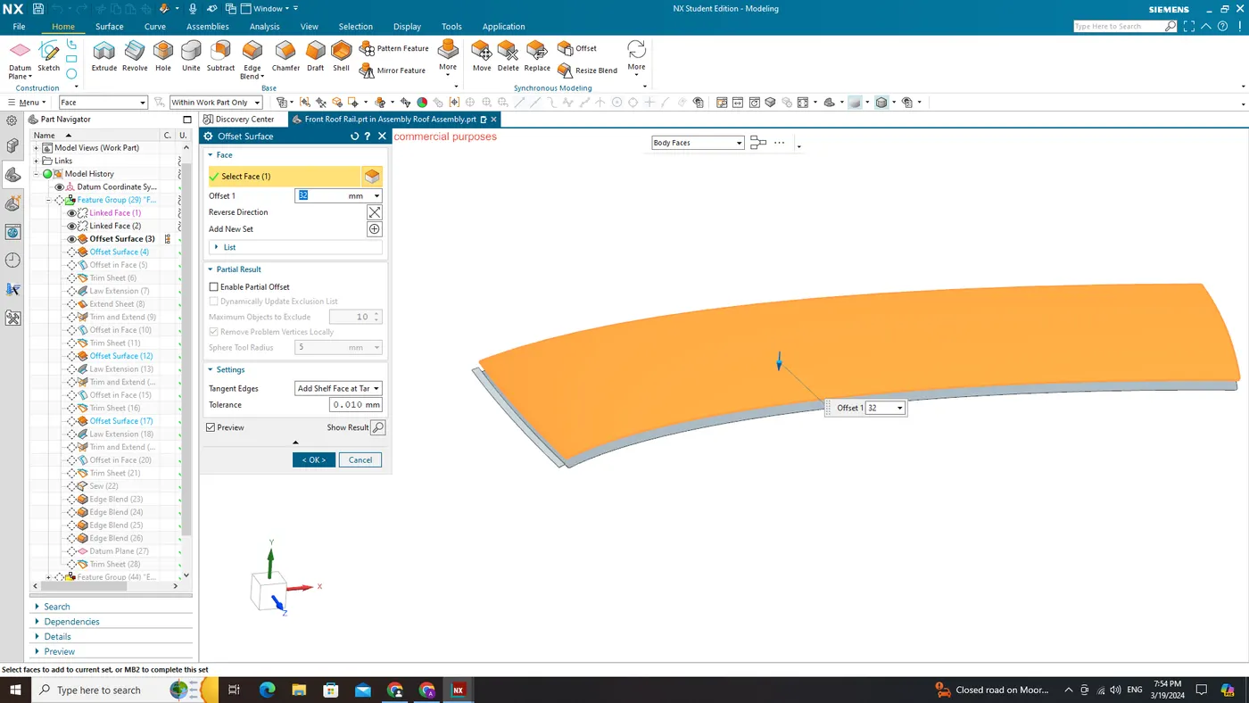
Thicken:
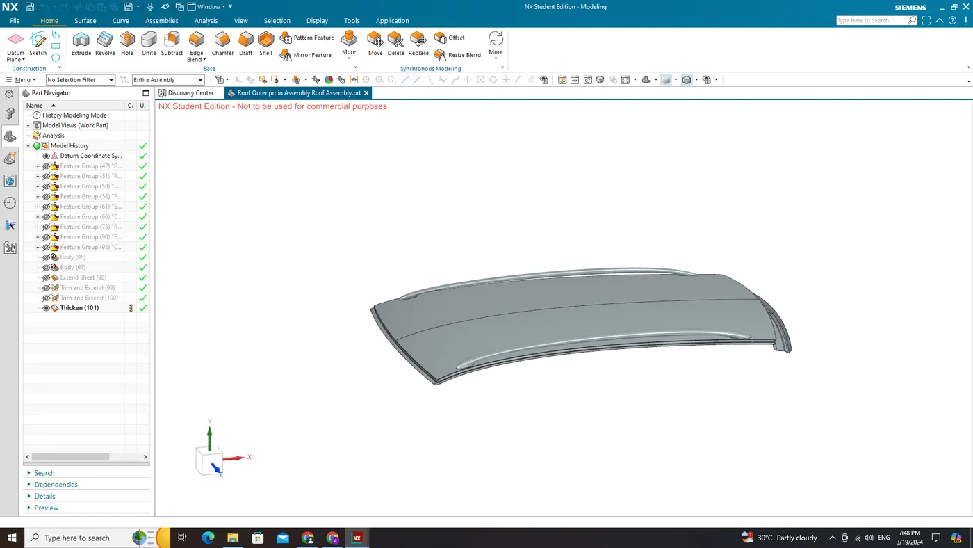
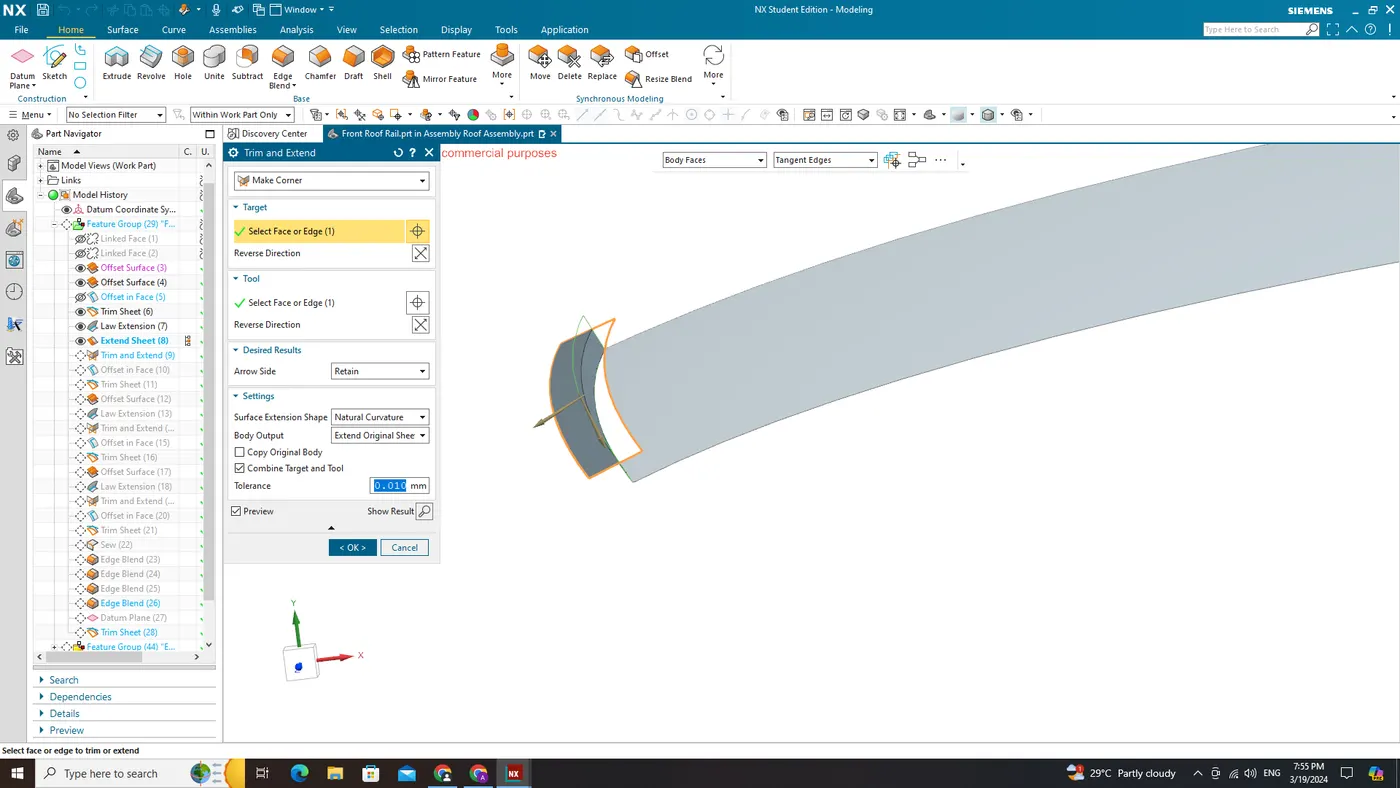
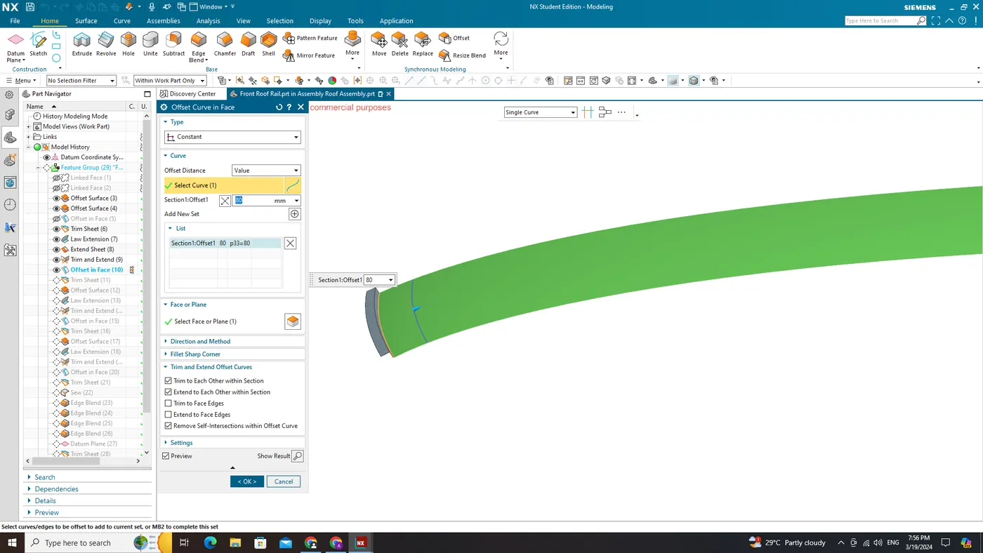
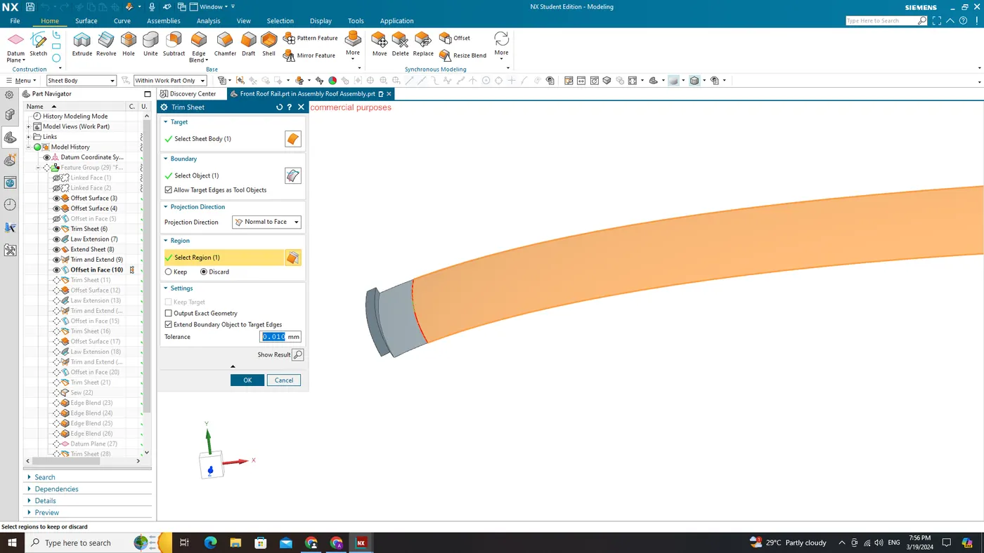
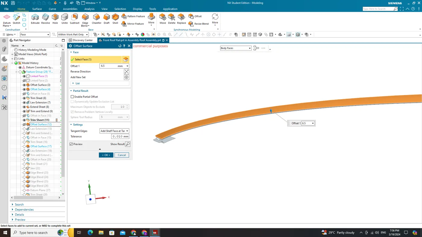
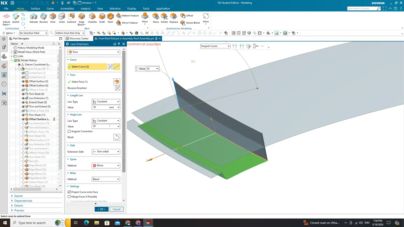
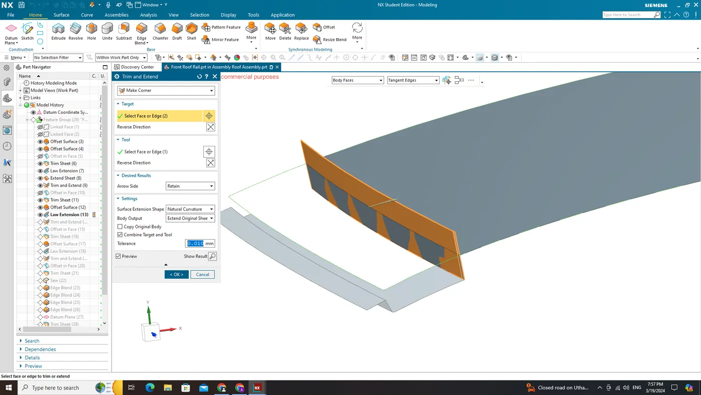
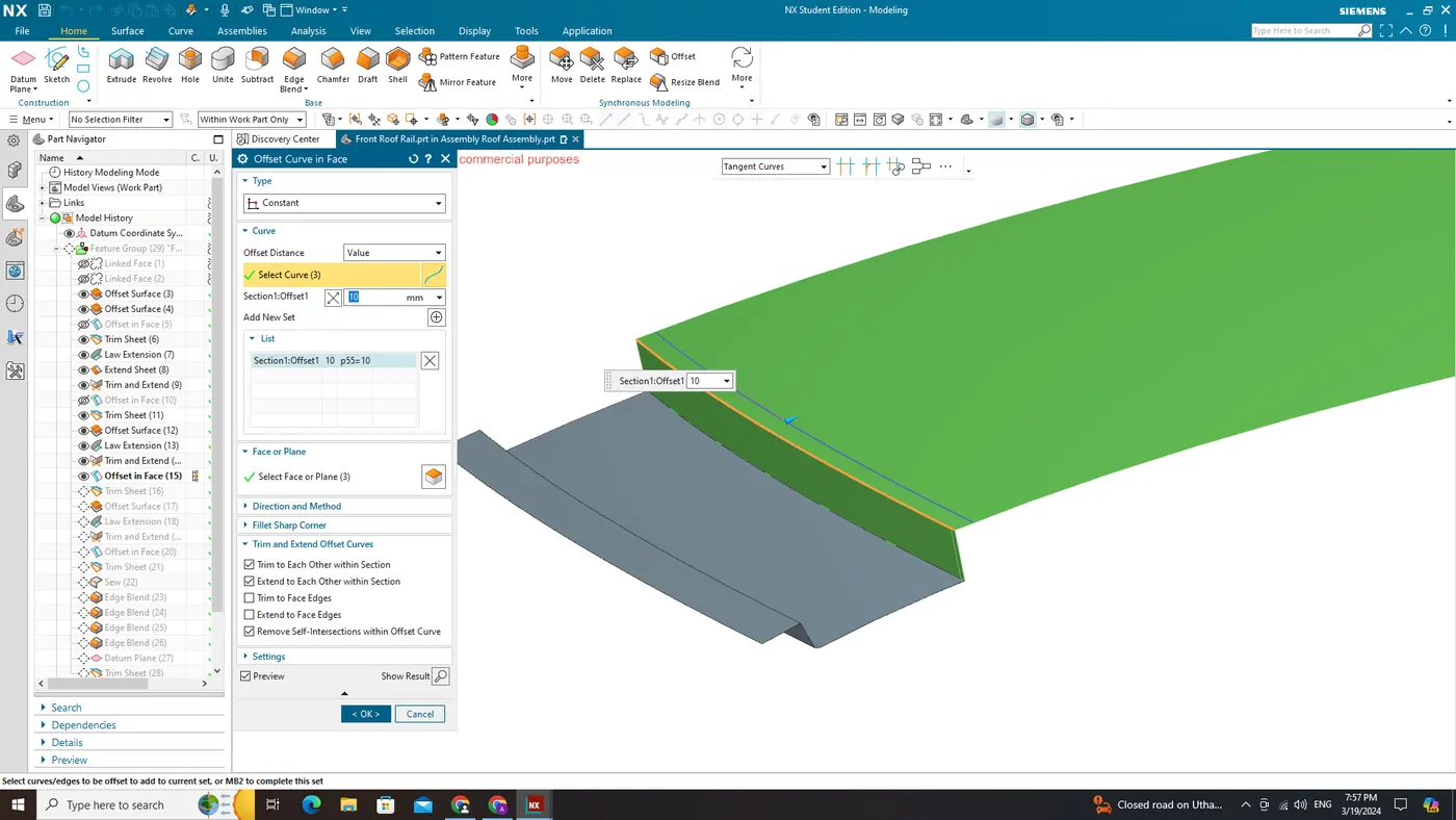
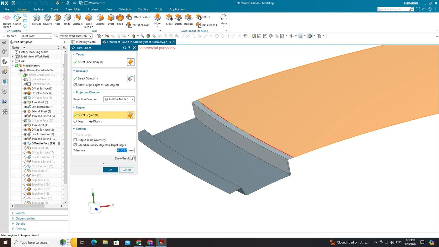
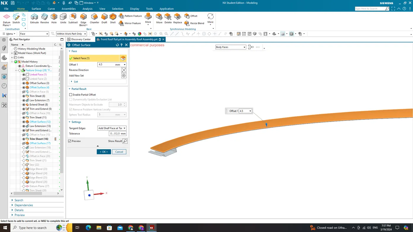
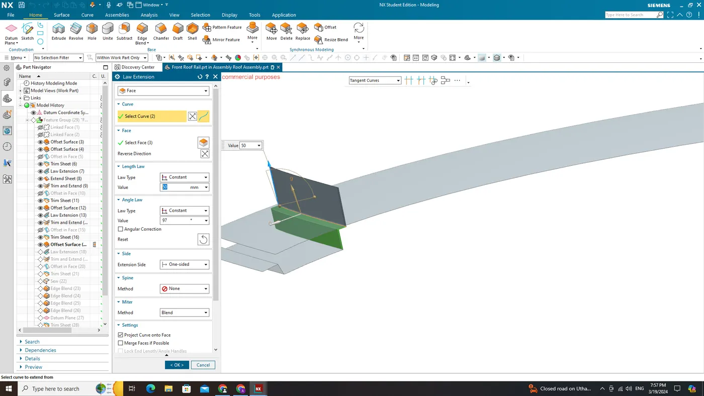
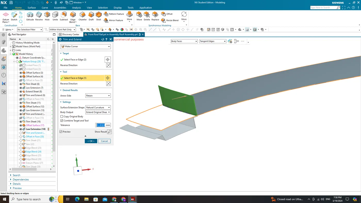
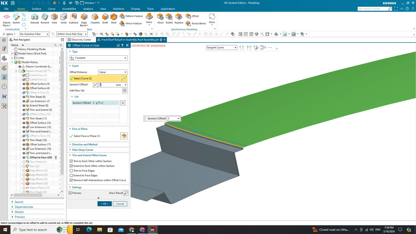
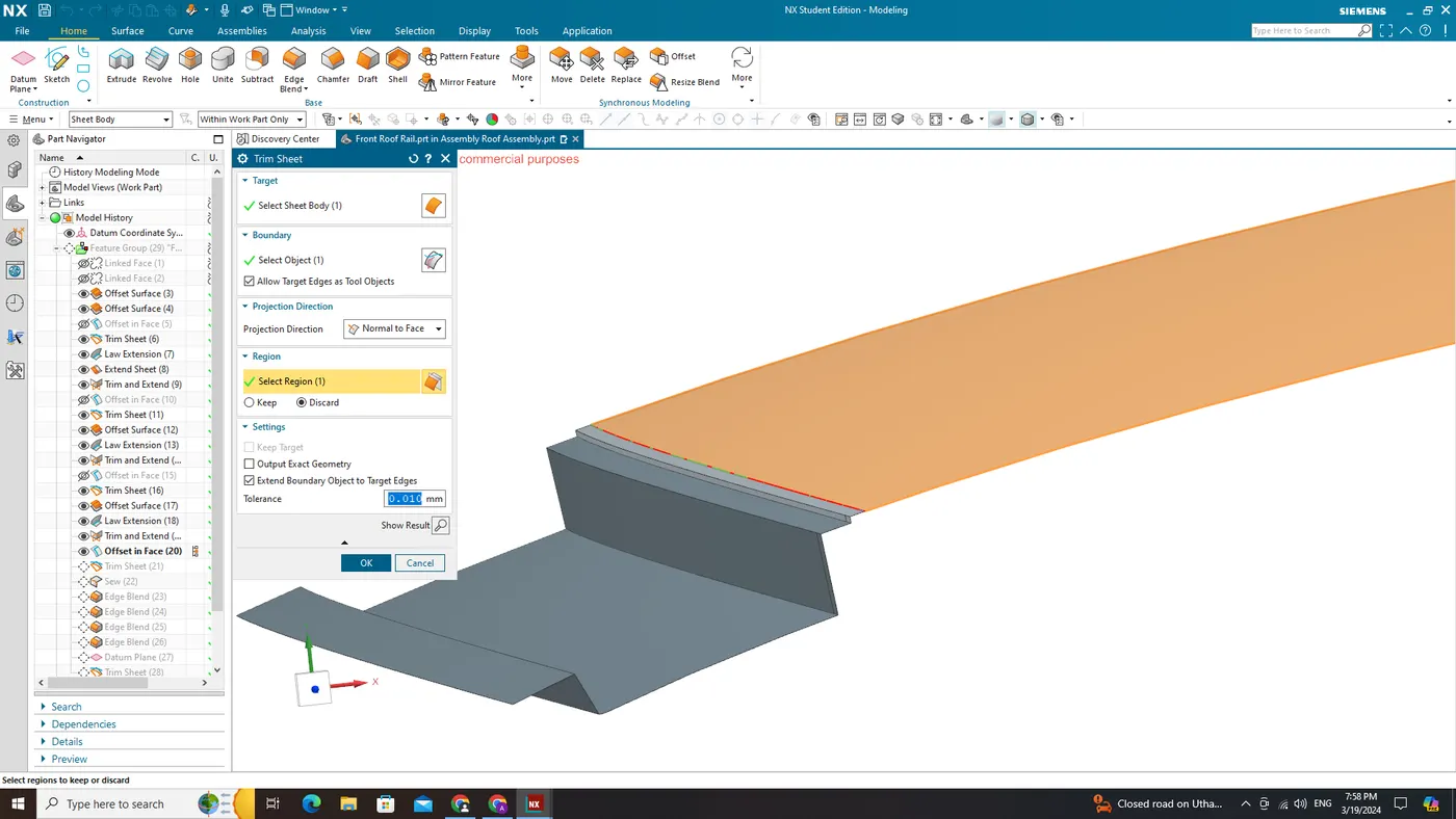
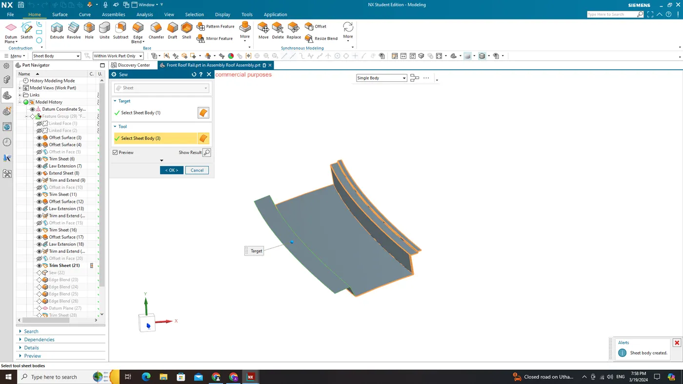
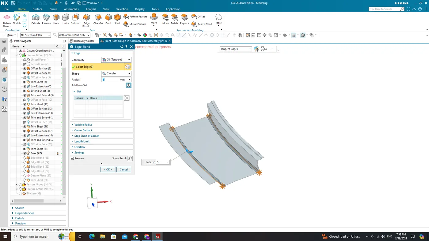
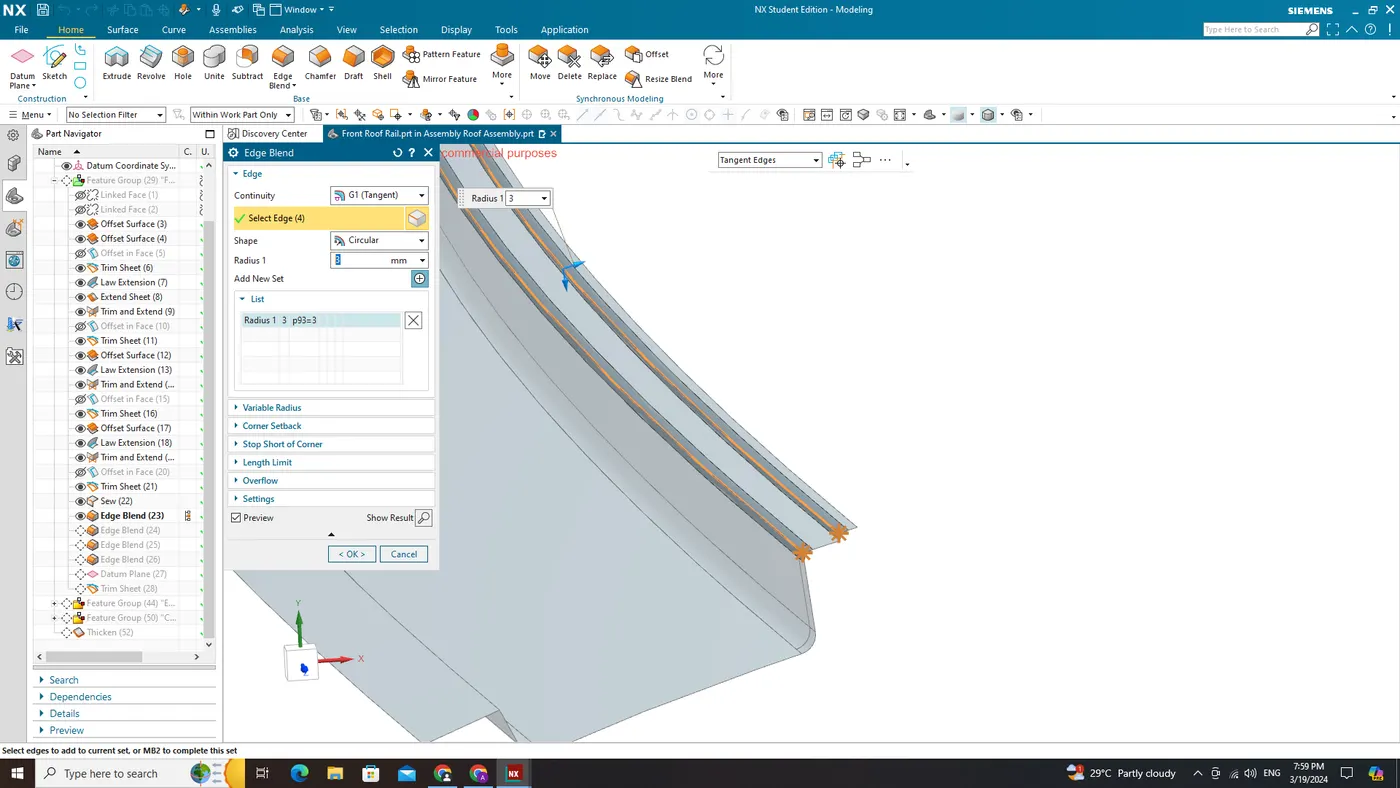
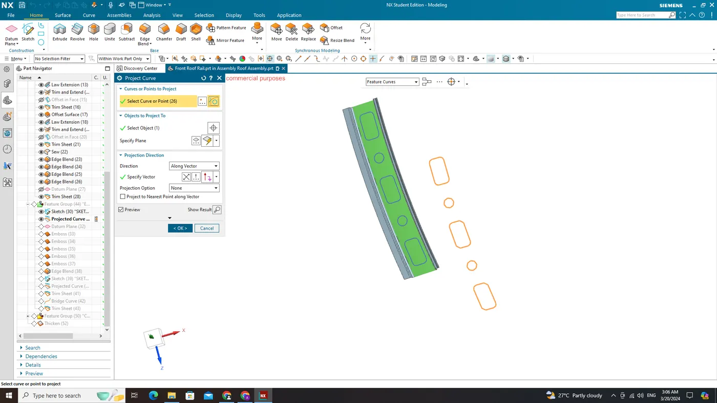
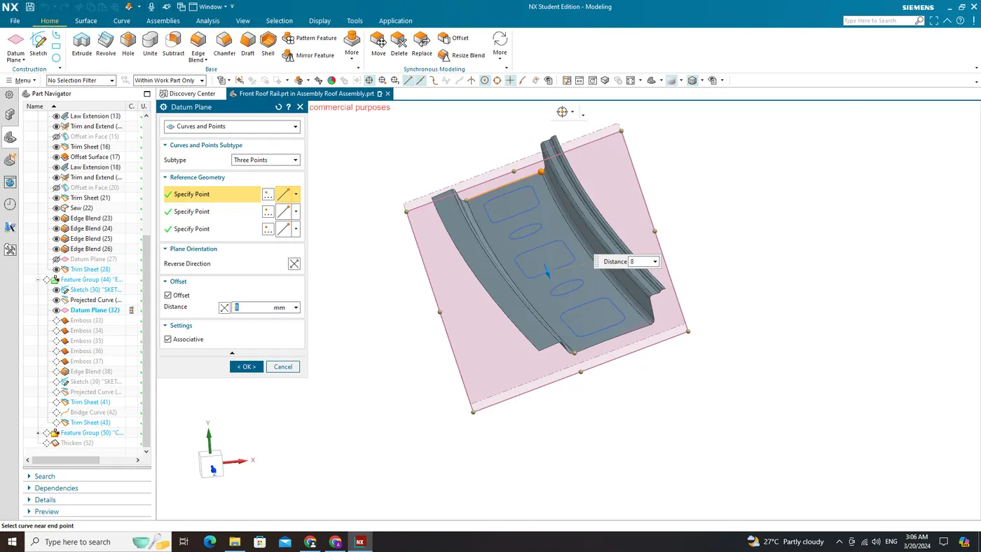
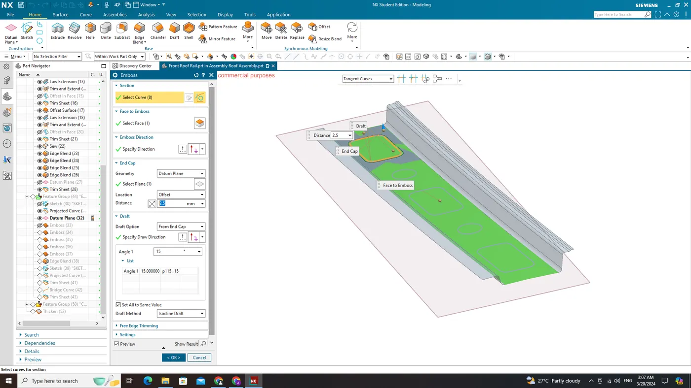
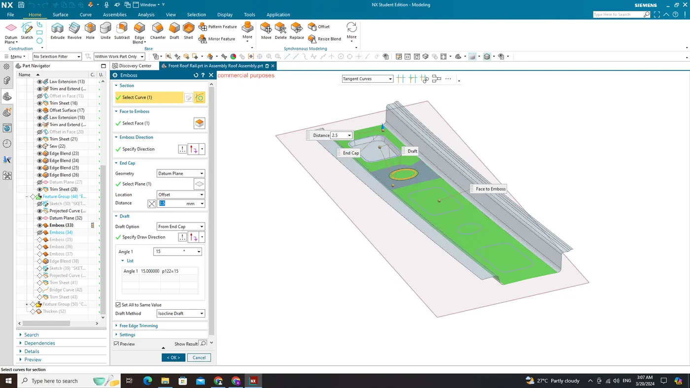
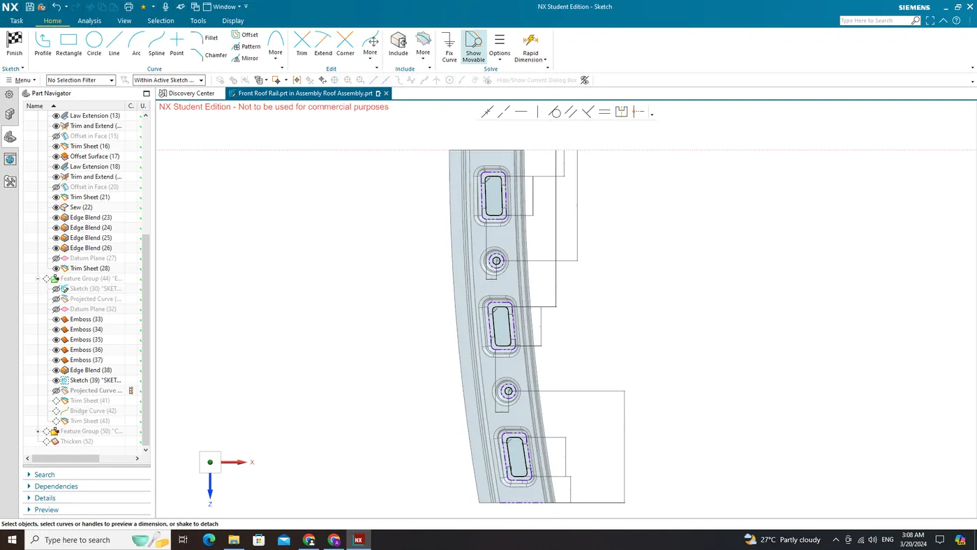
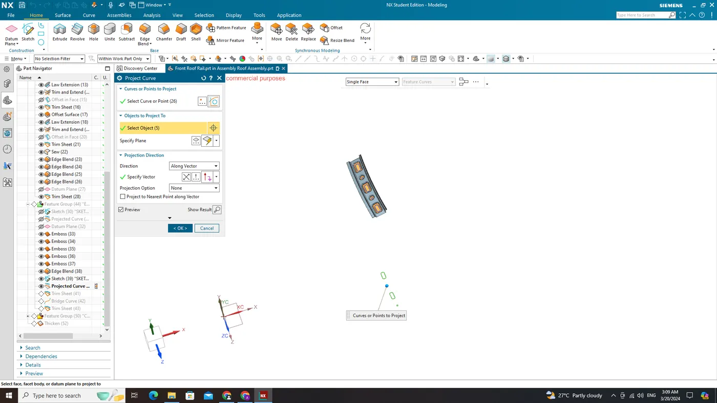
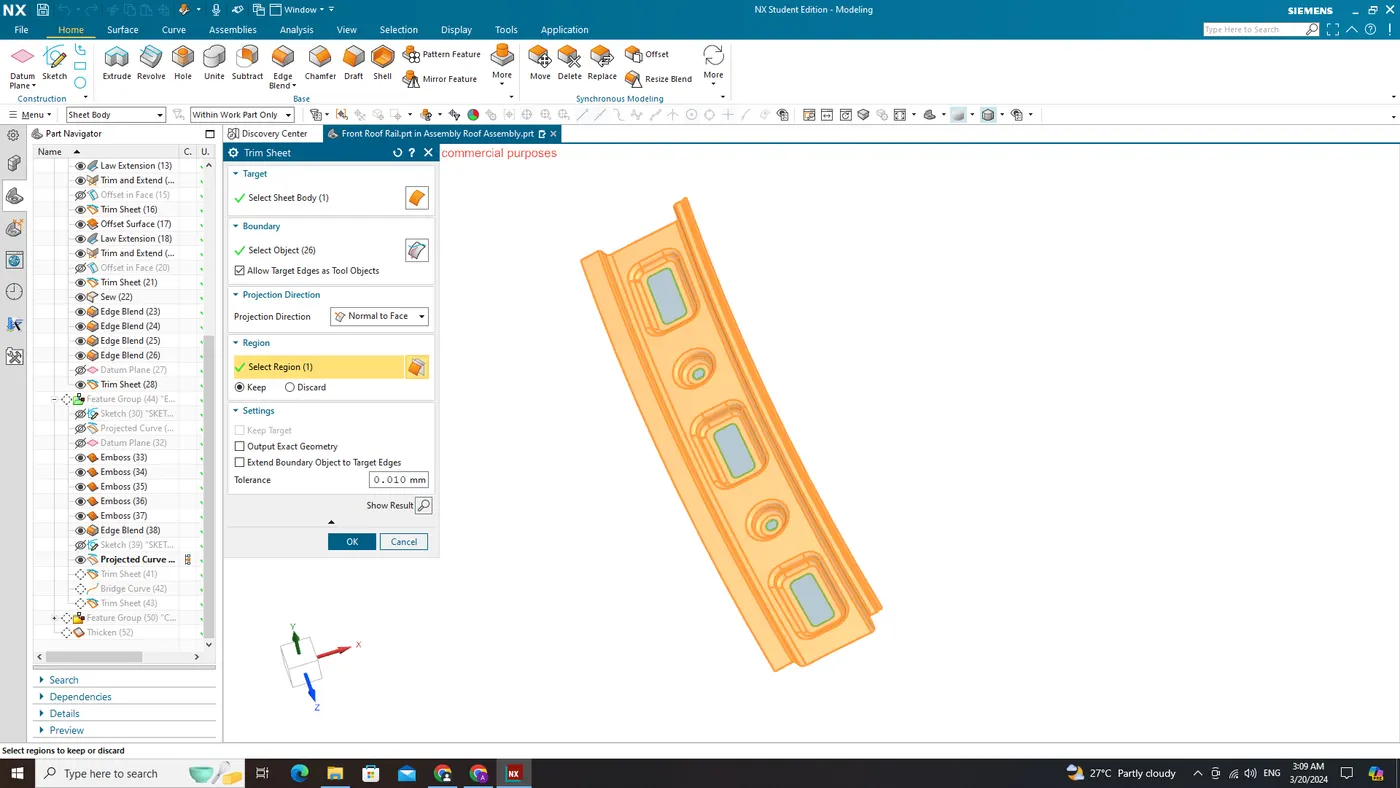
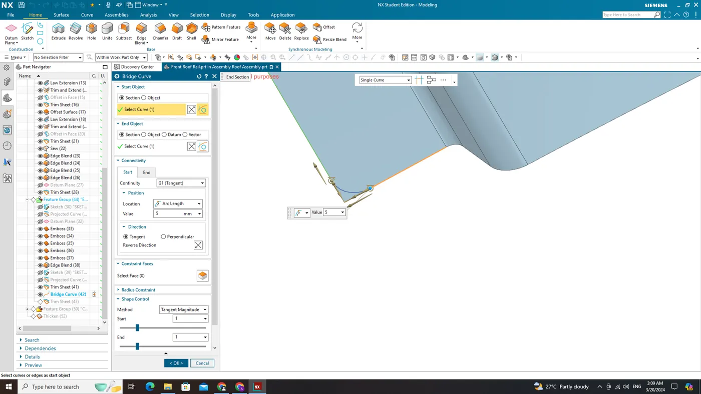
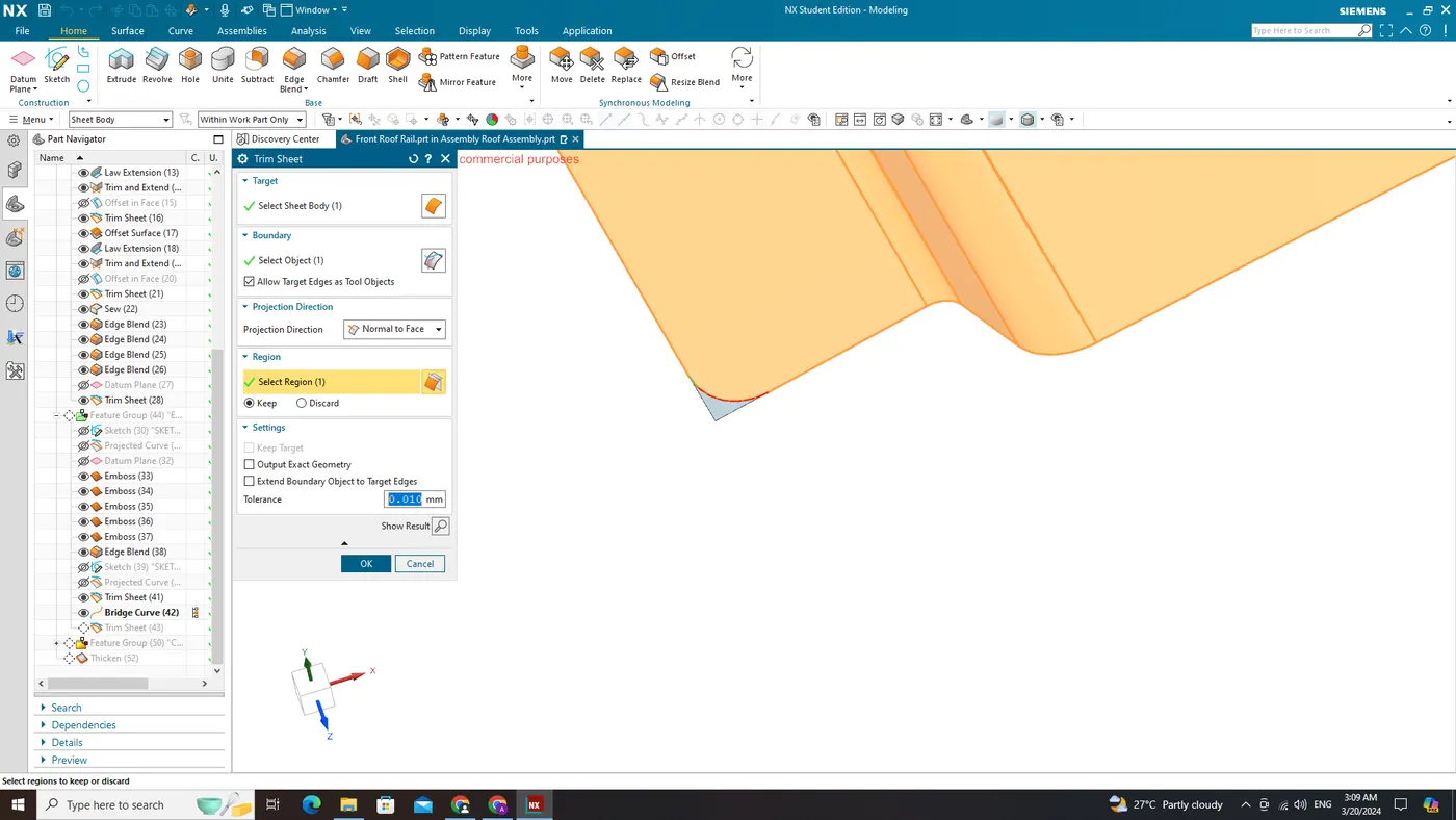
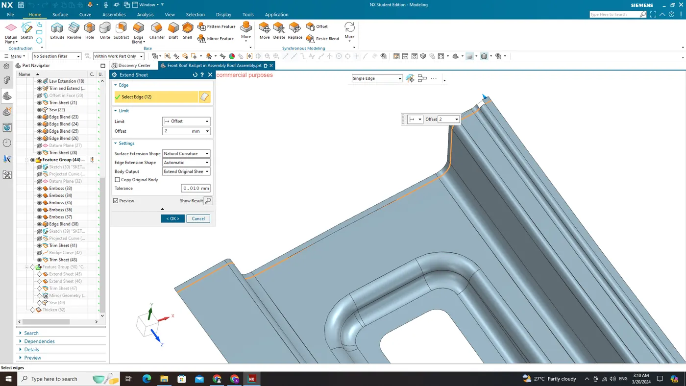
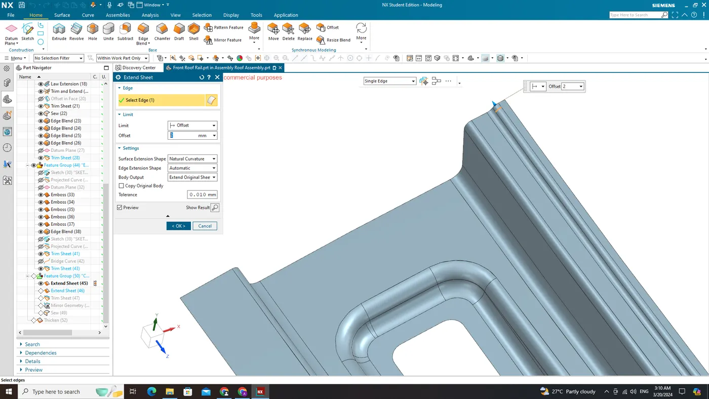
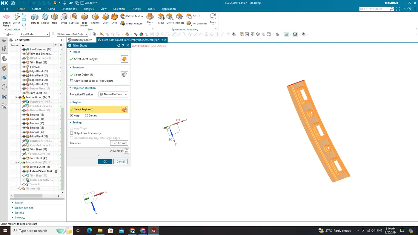
Front Roof Rail
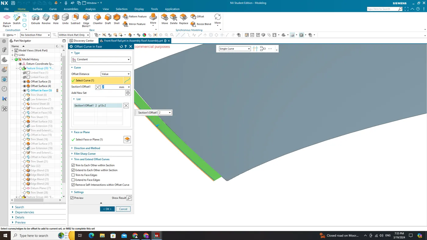
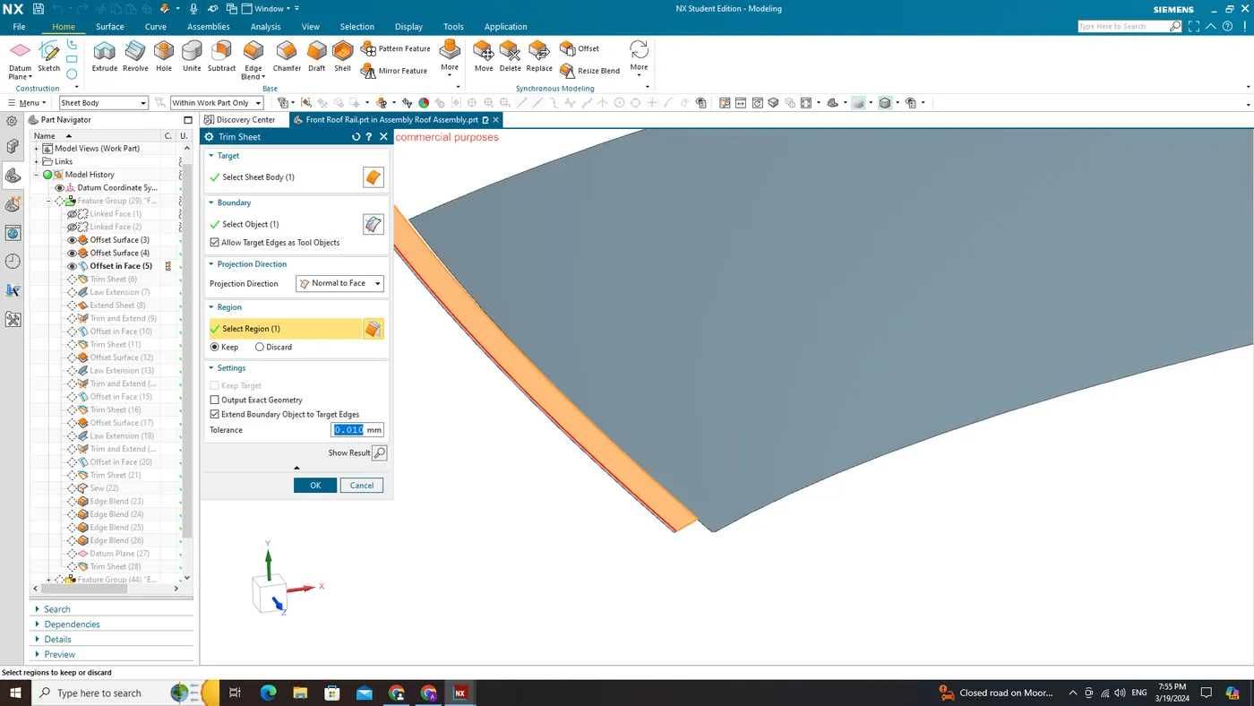
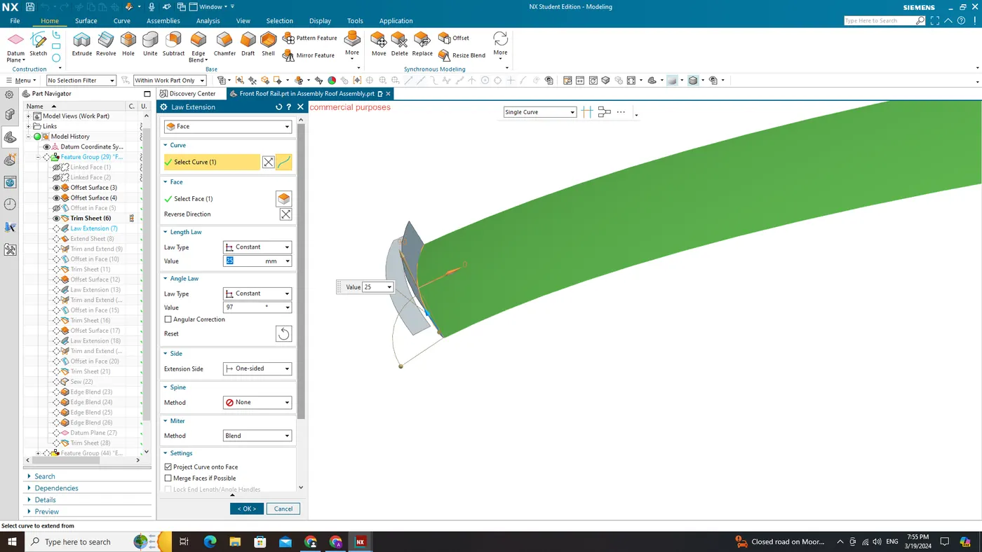
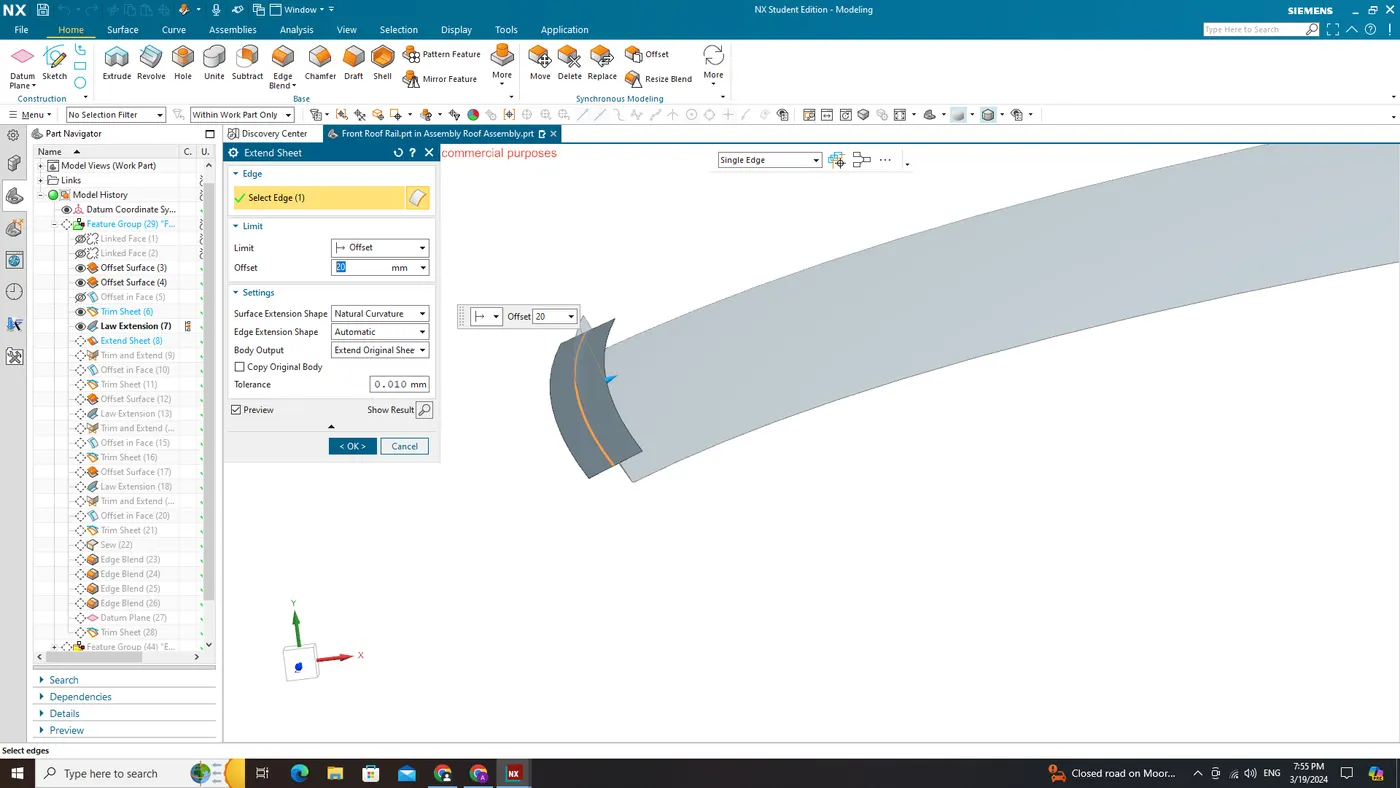
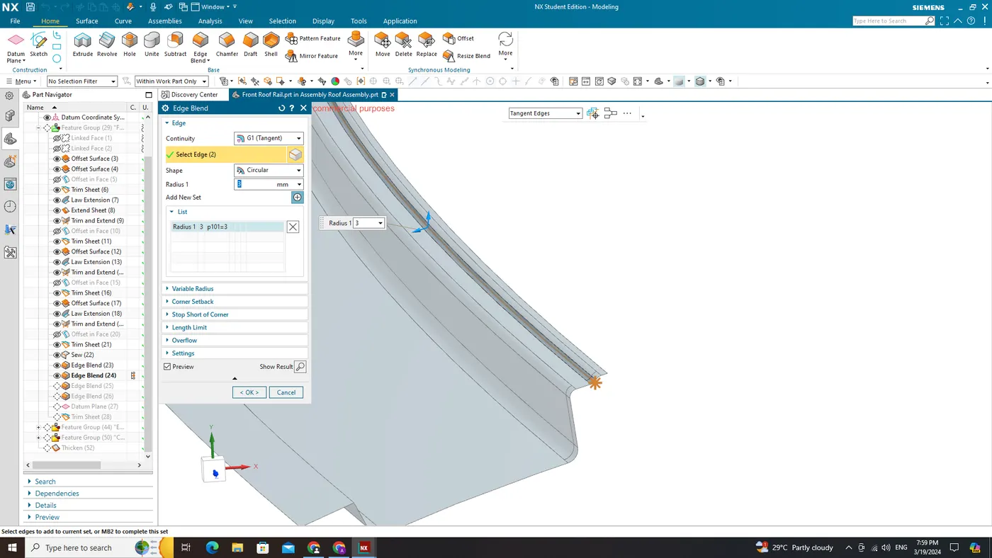
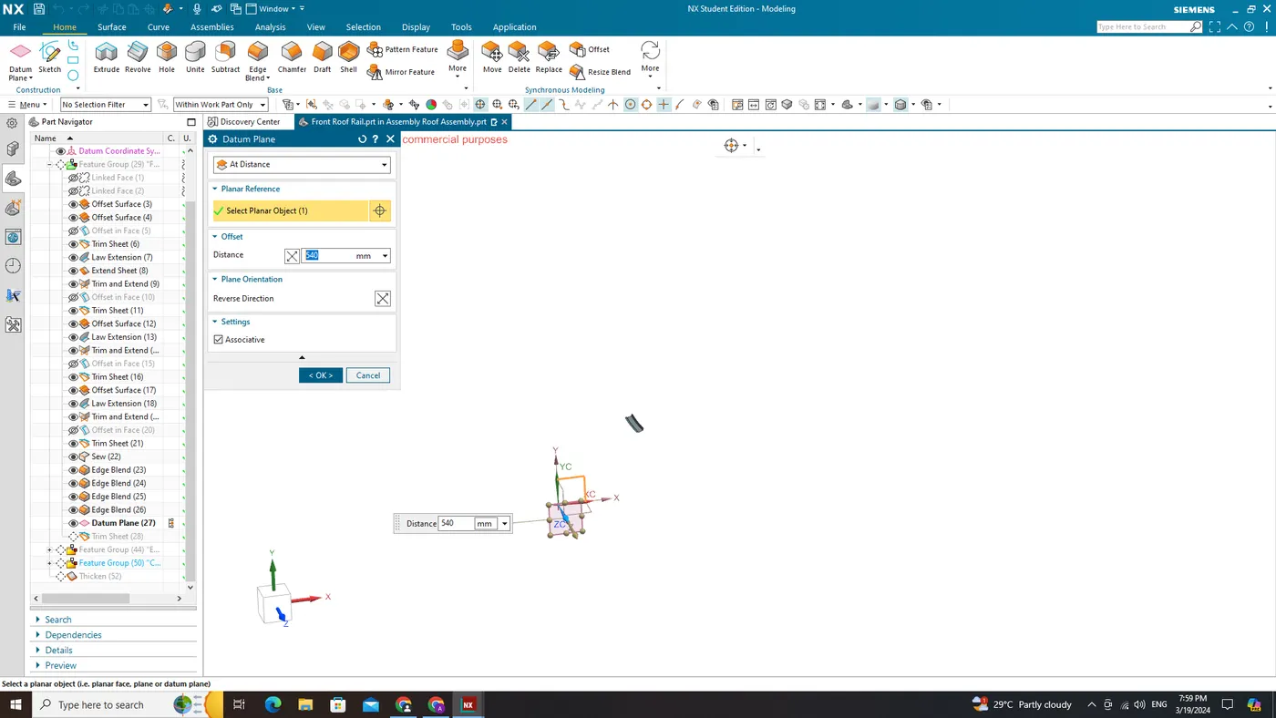
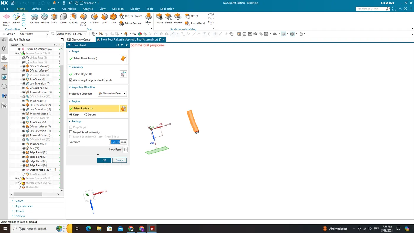
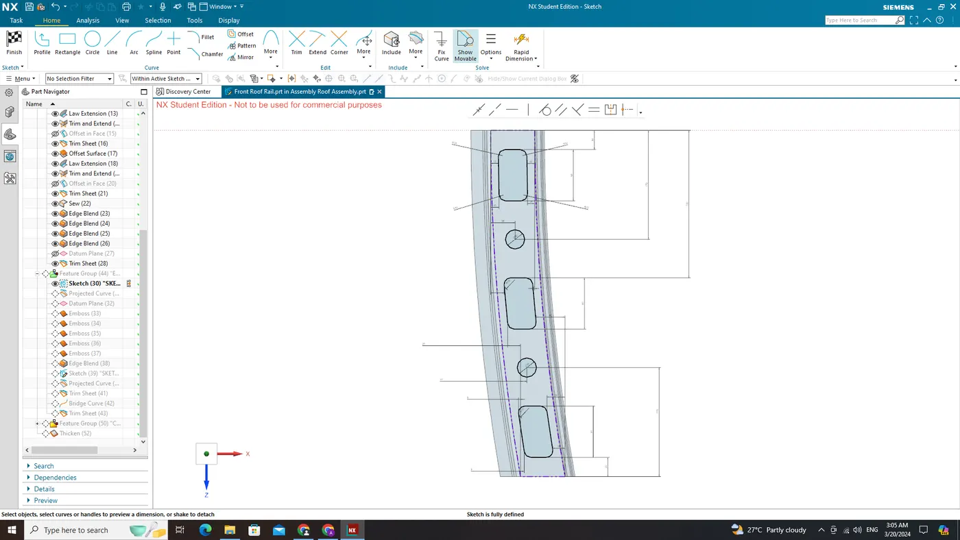
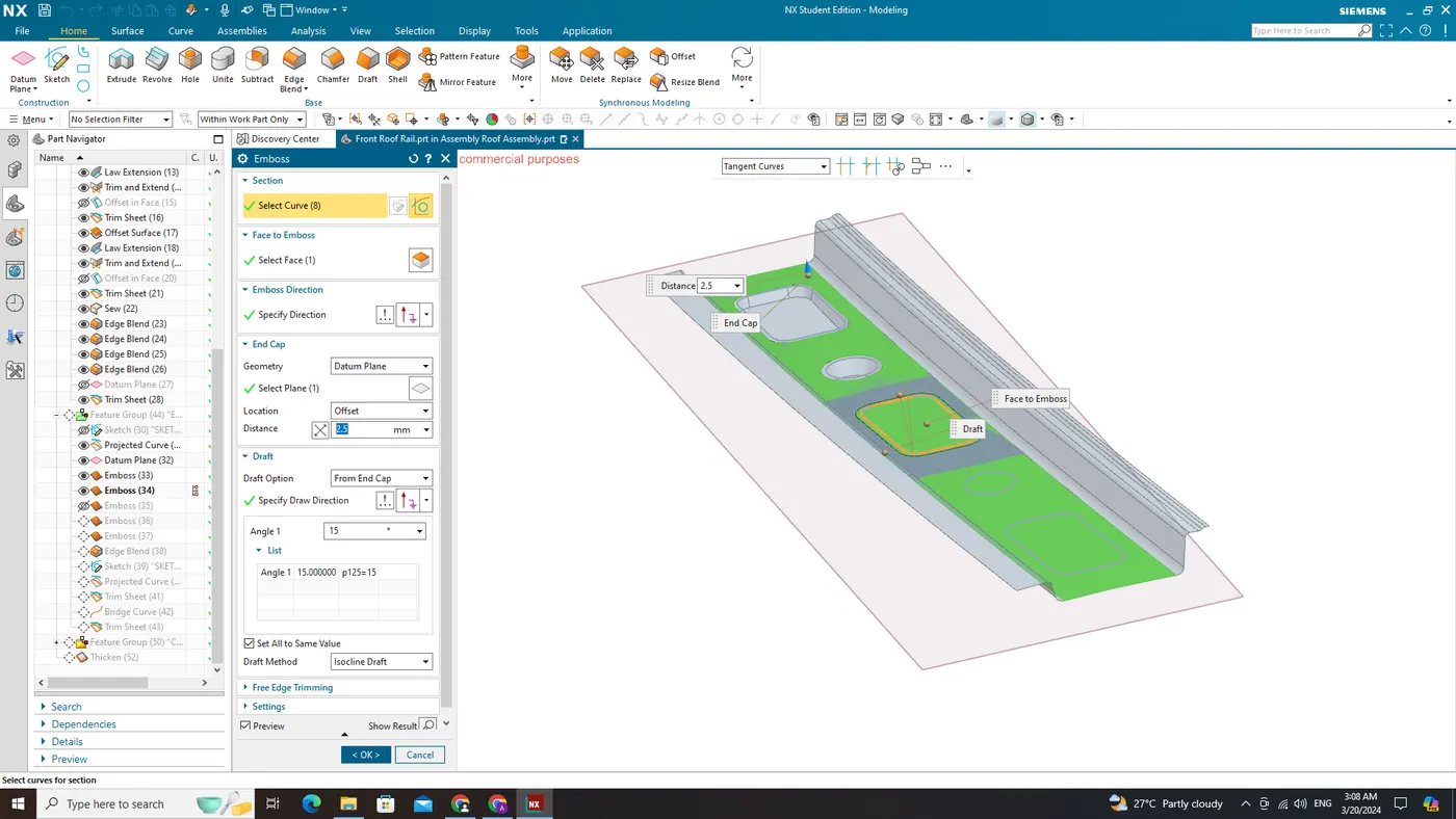
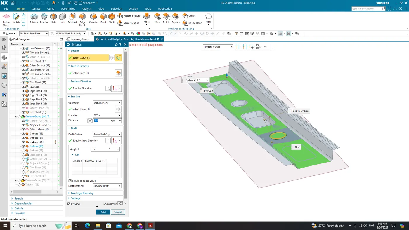
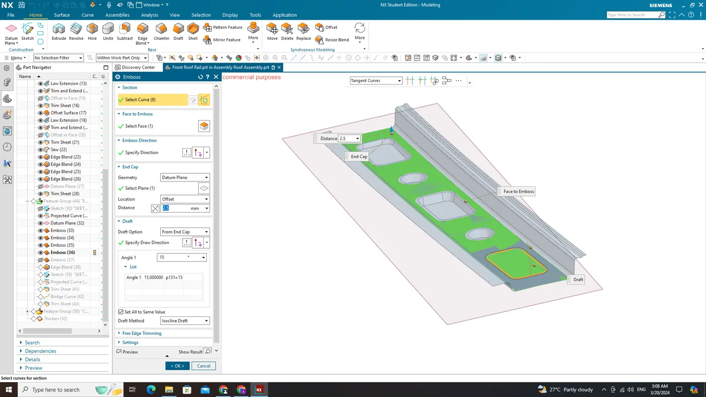
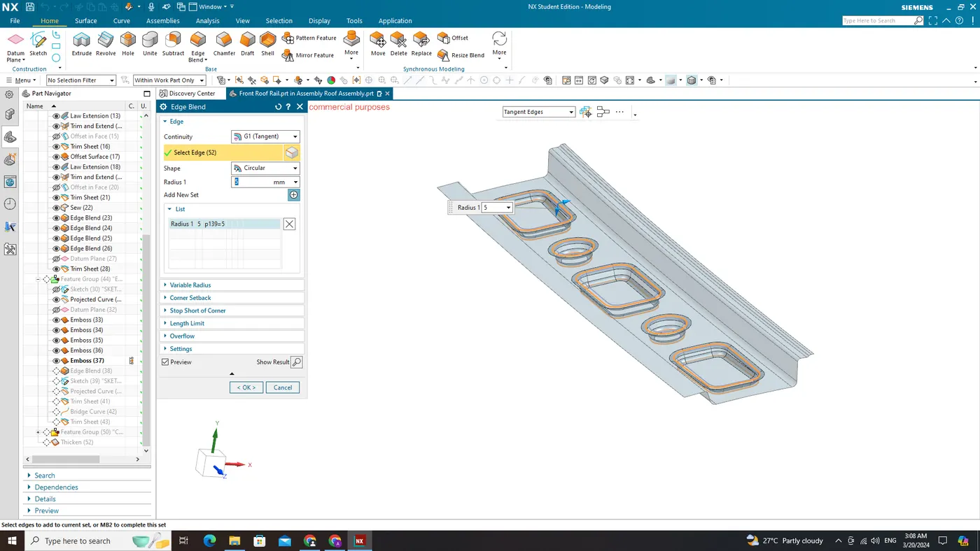
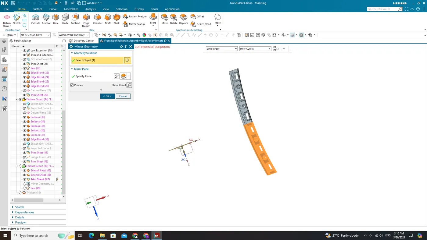
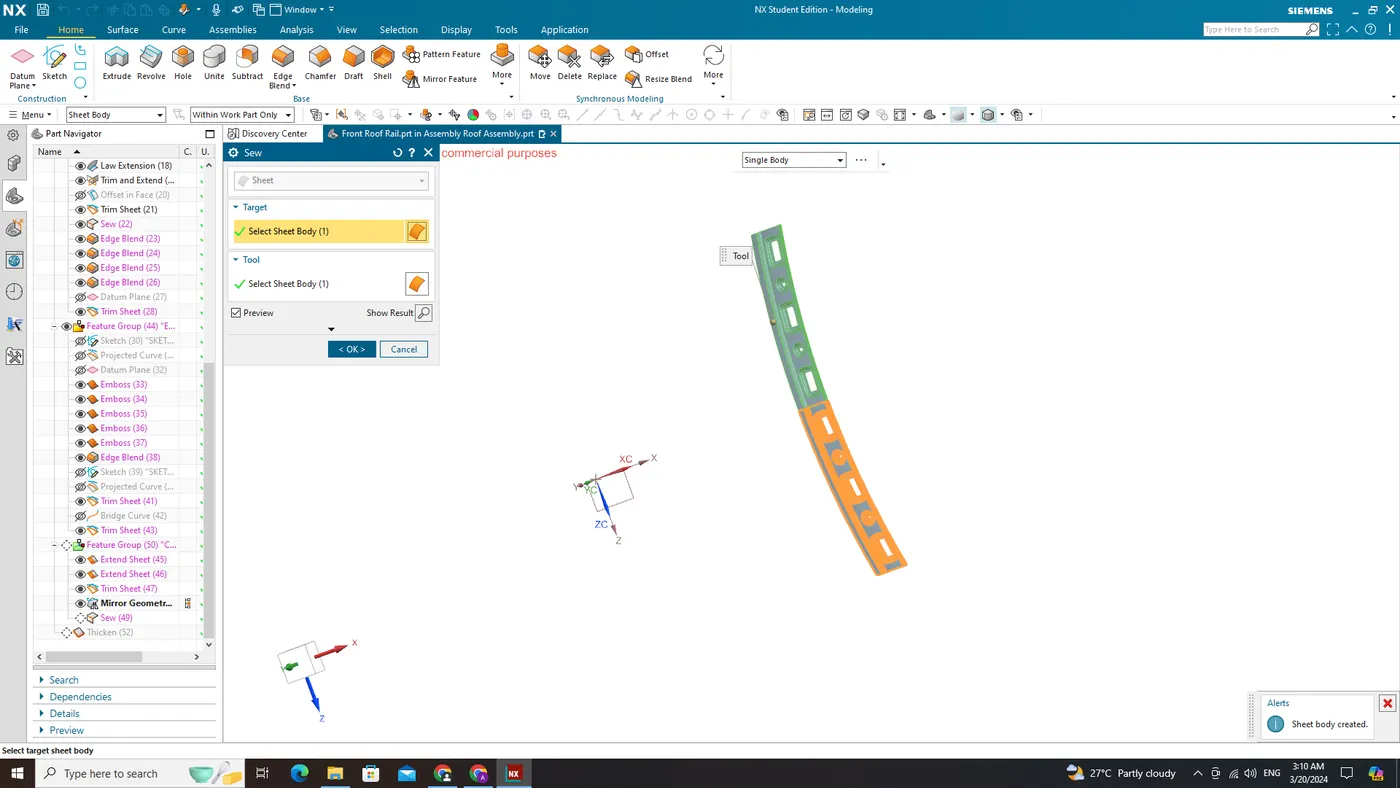
Thicken:
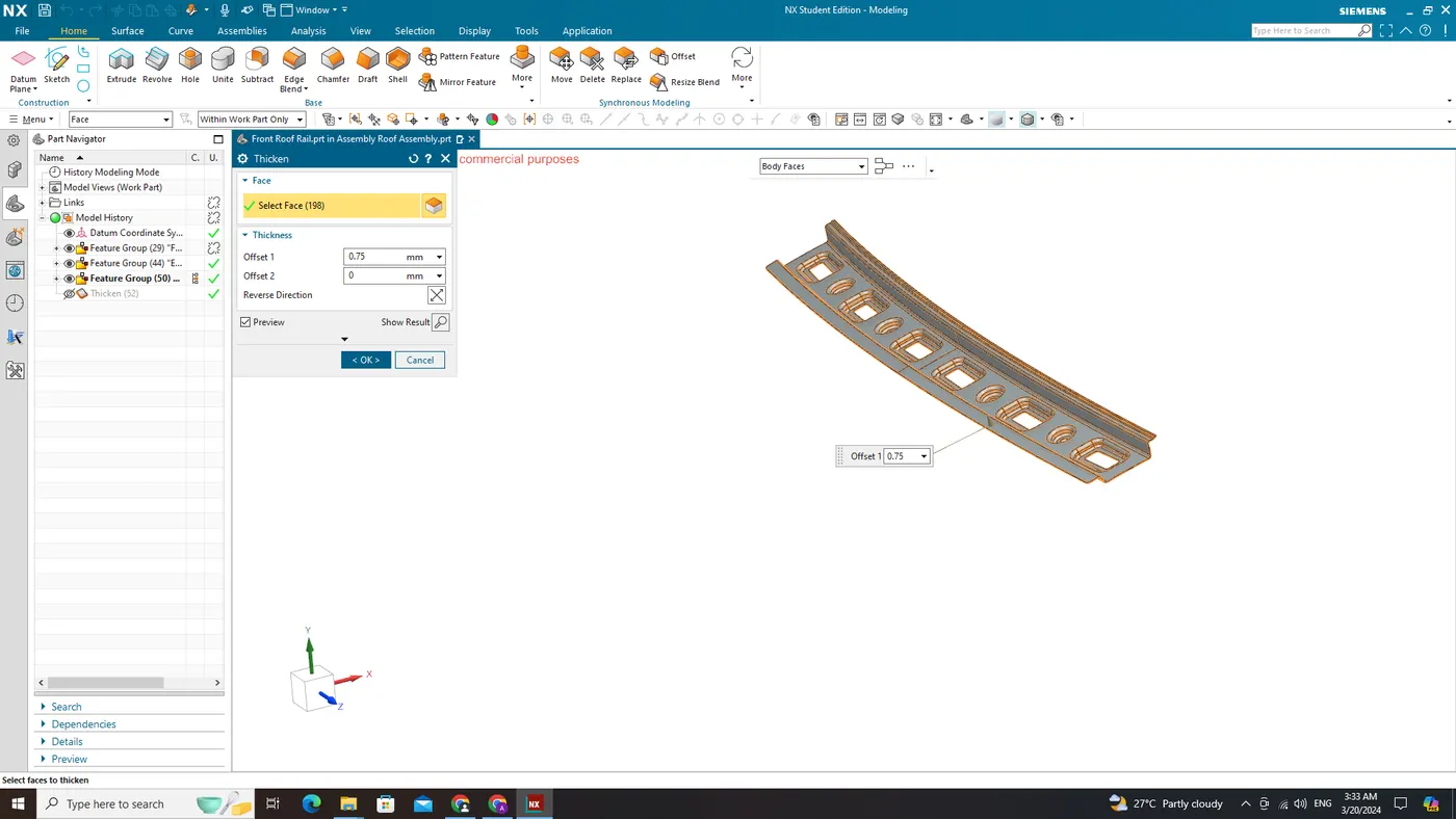
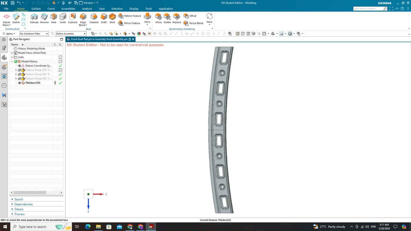
Rear Roof Rail
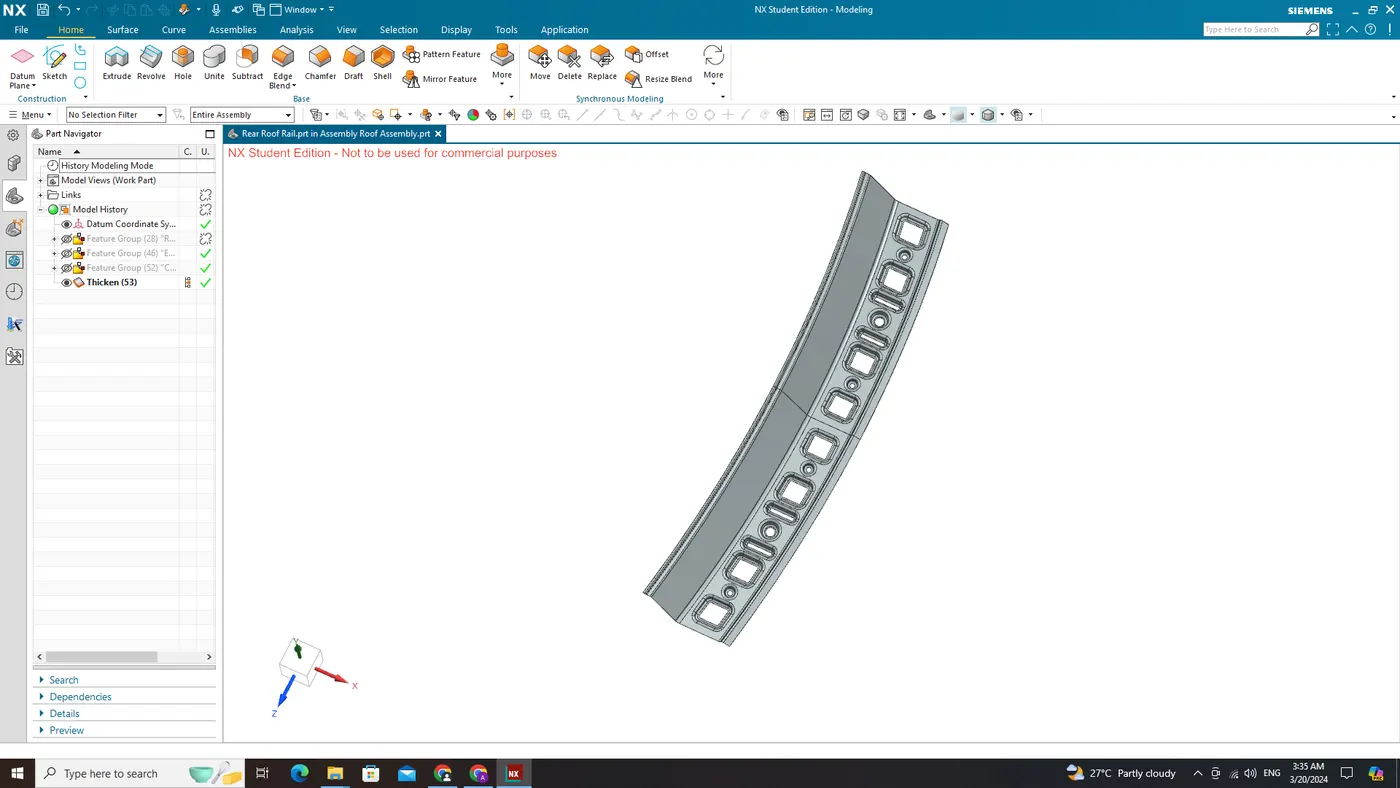
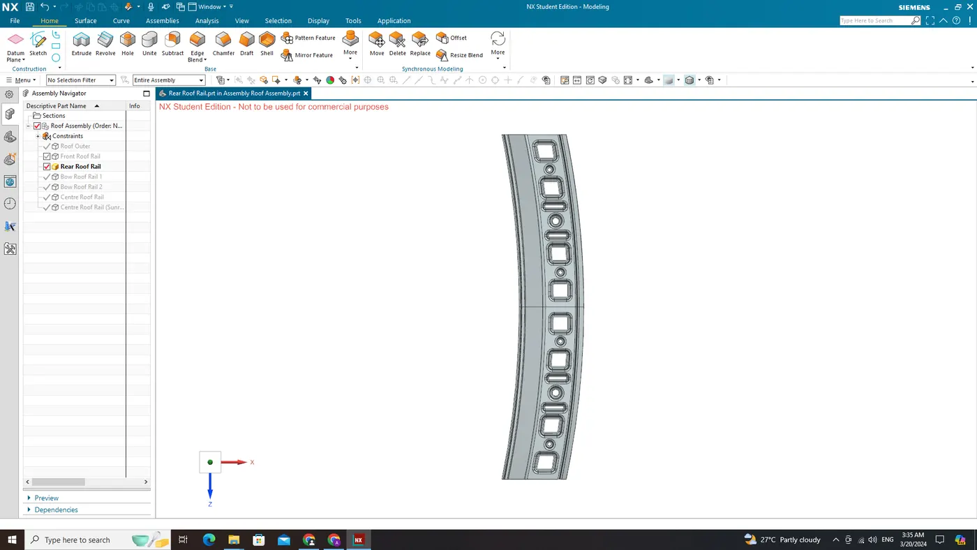
Roof Rails
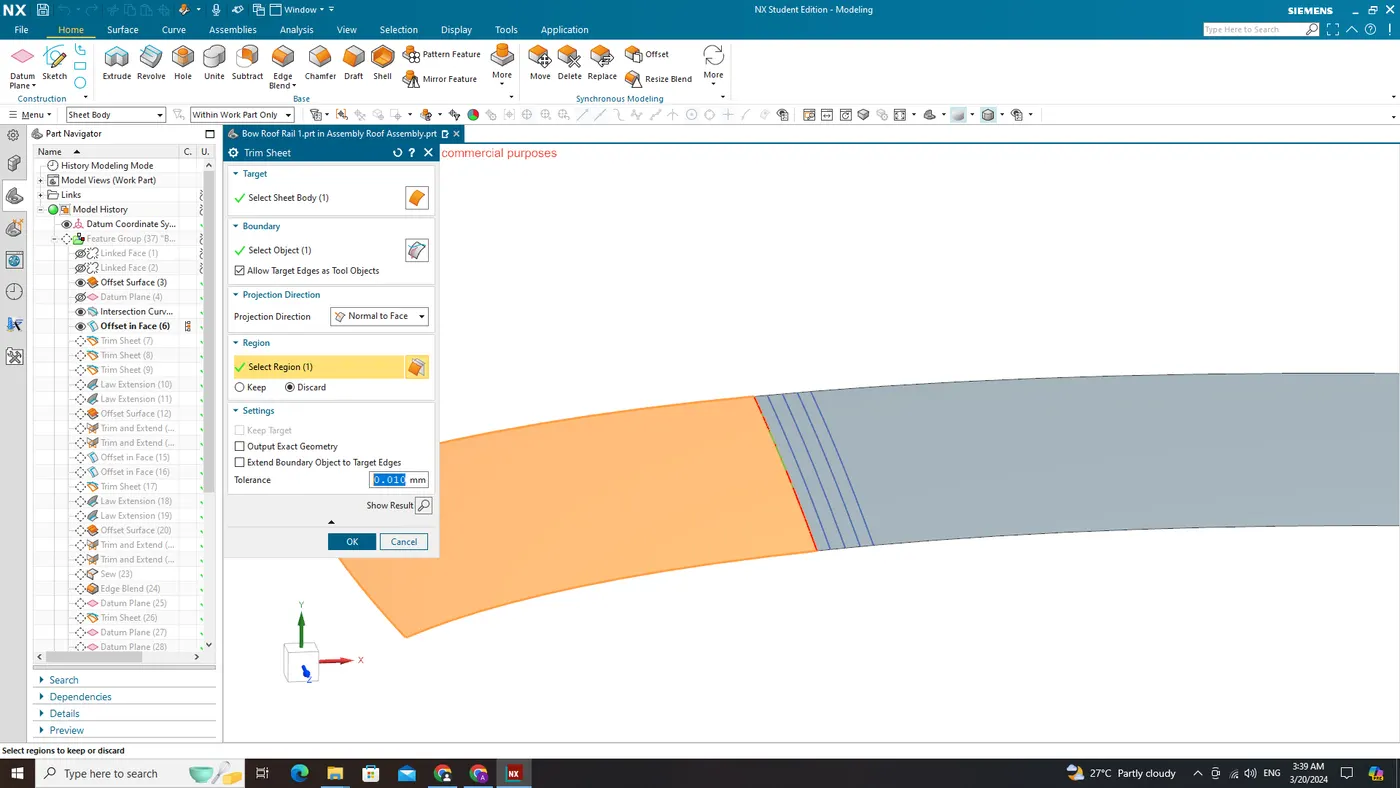
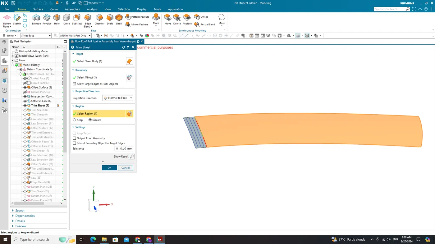
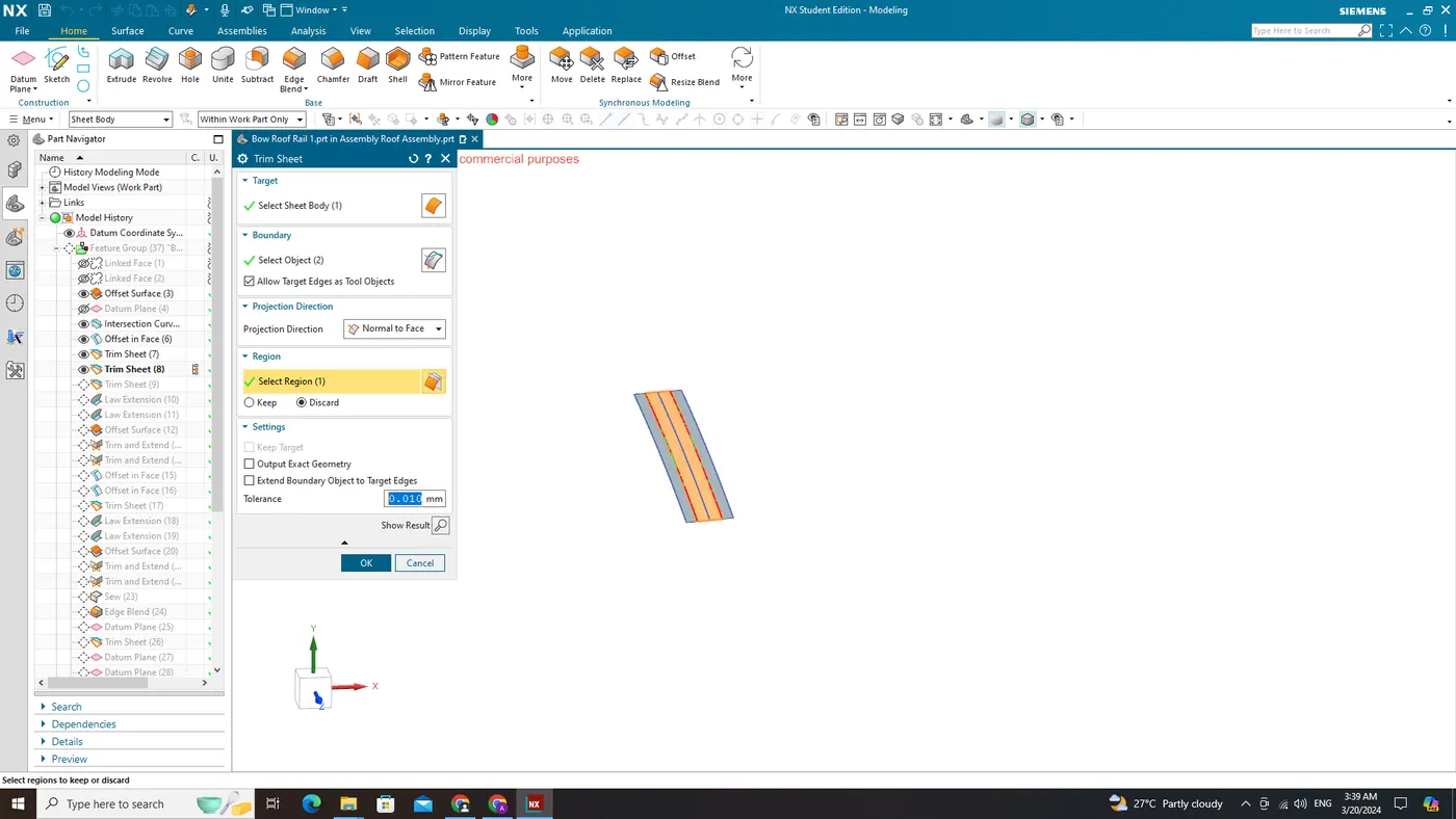
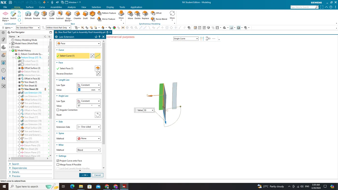
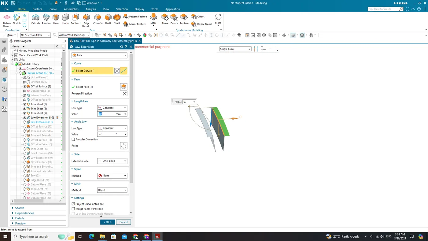
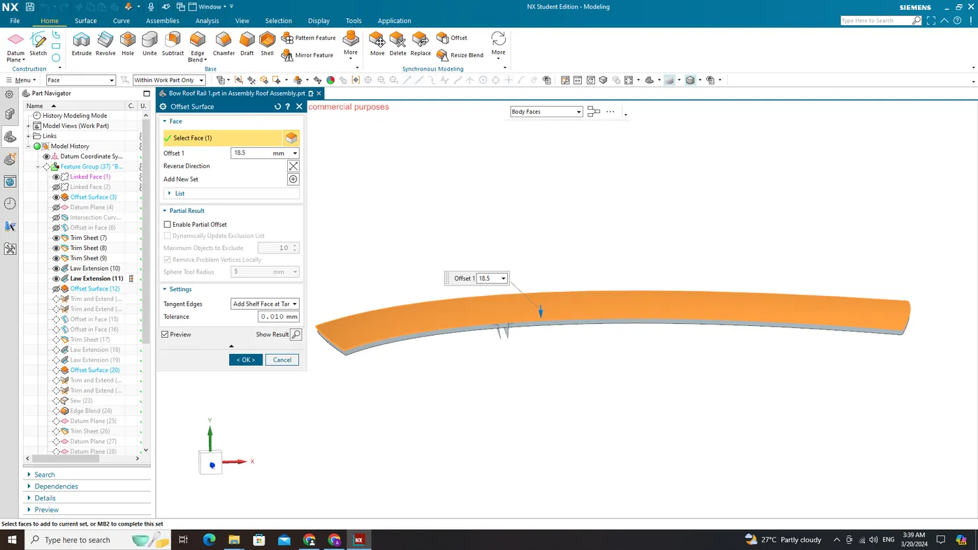
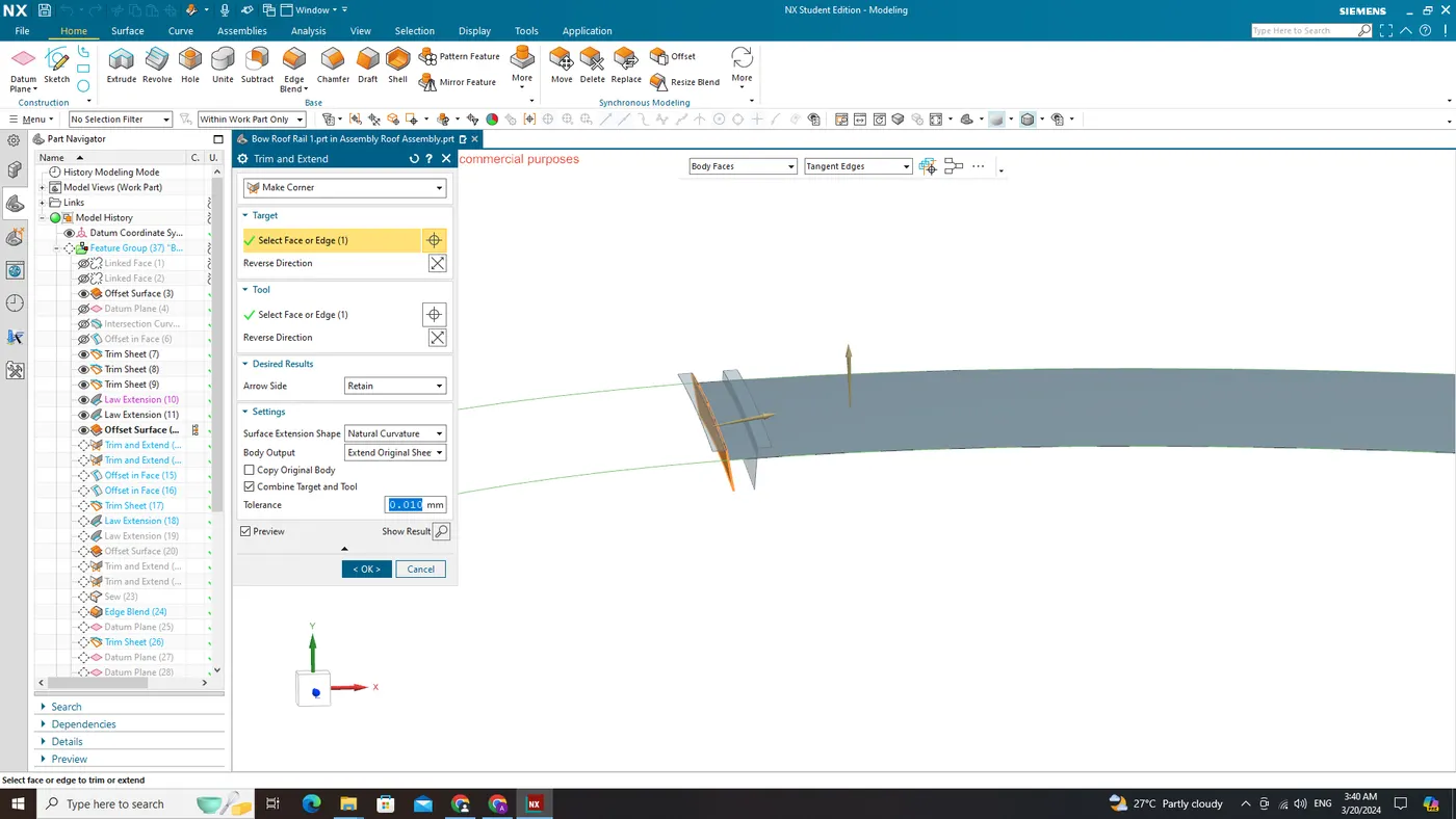
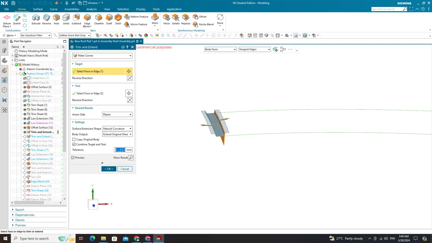
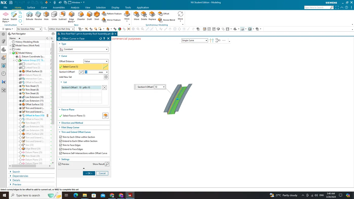
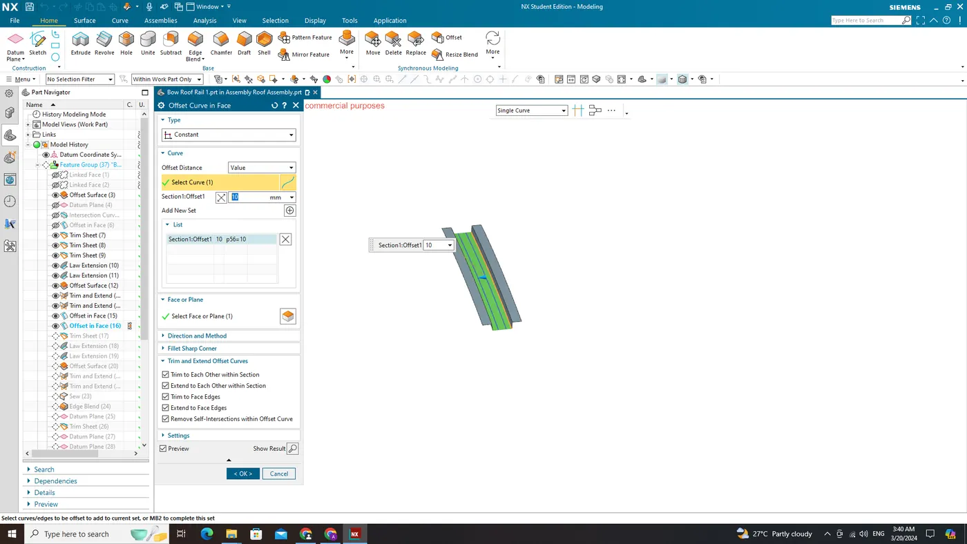
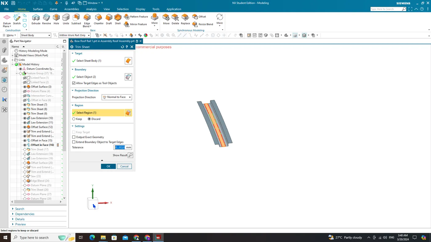
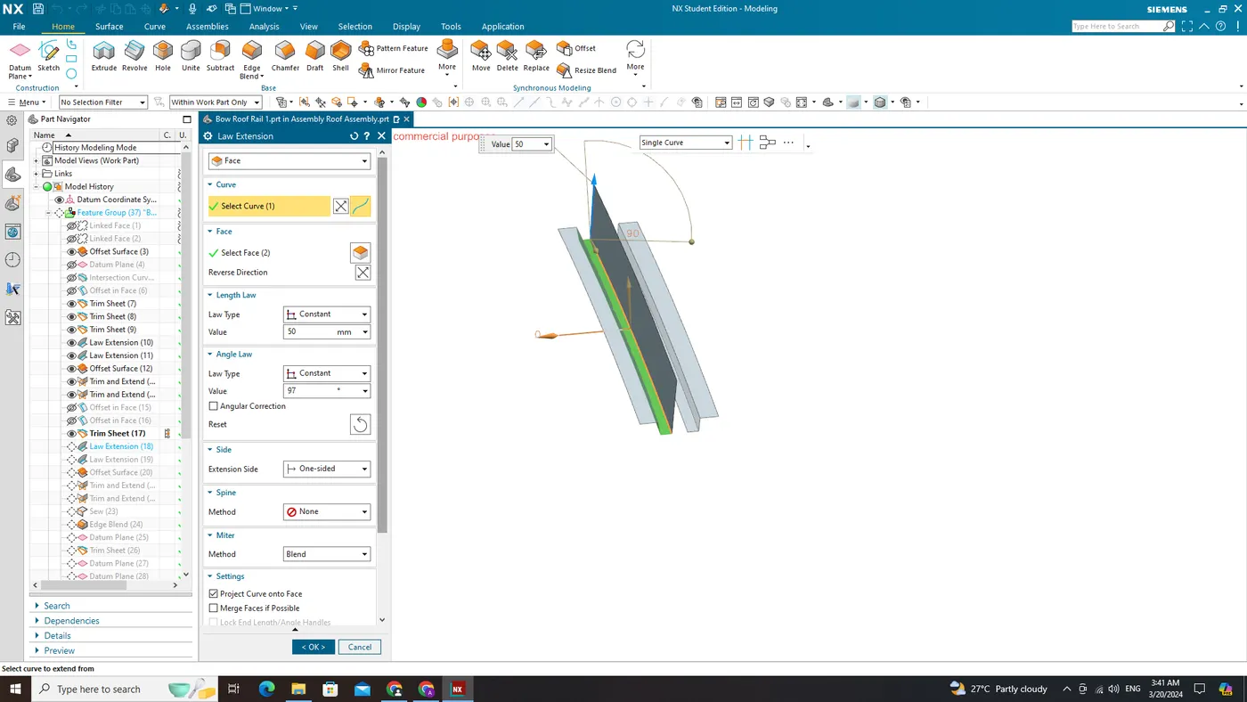
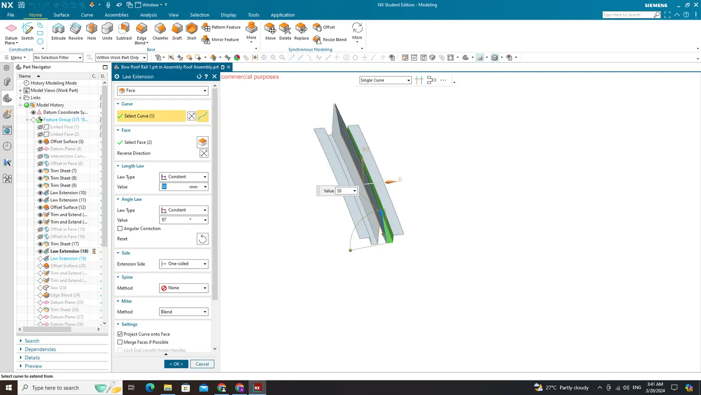
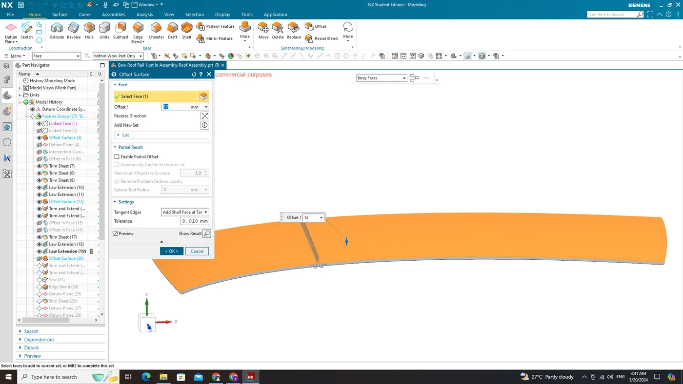
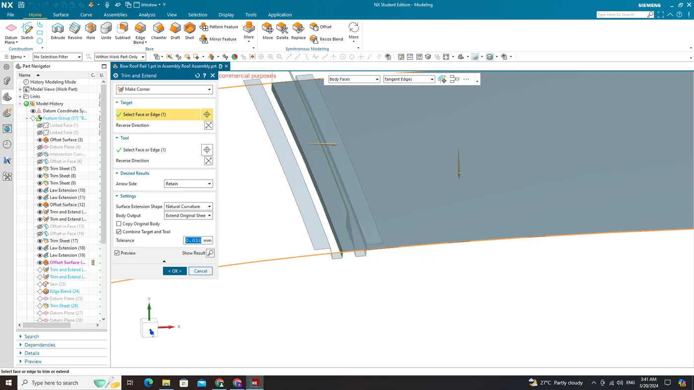
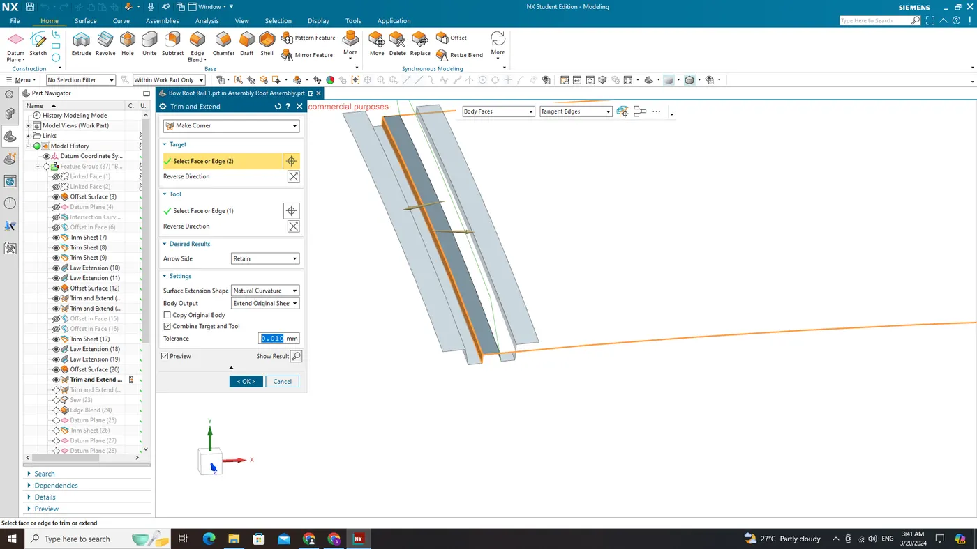
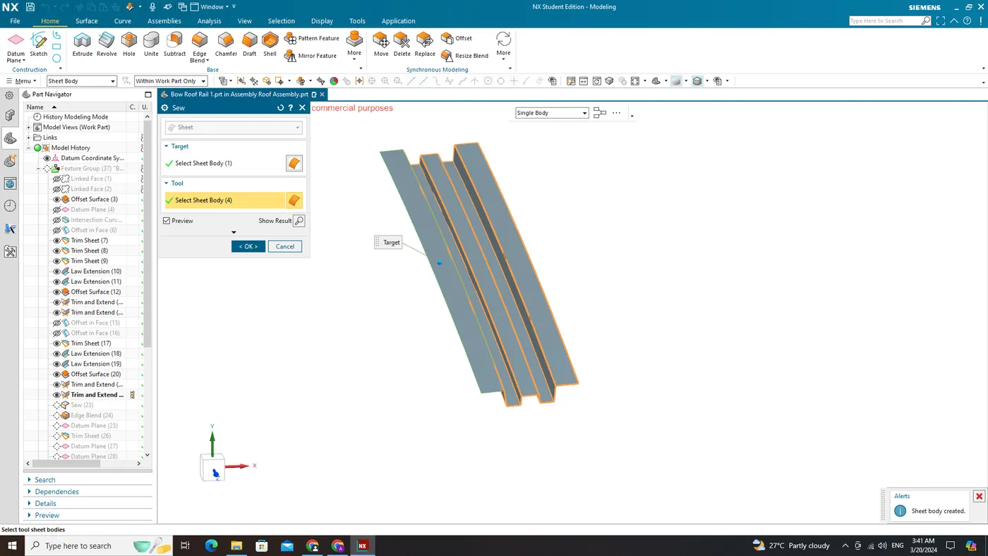
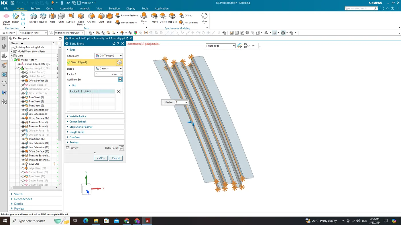
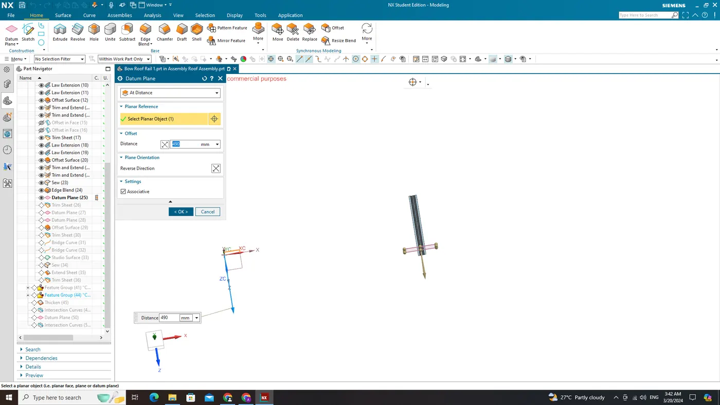
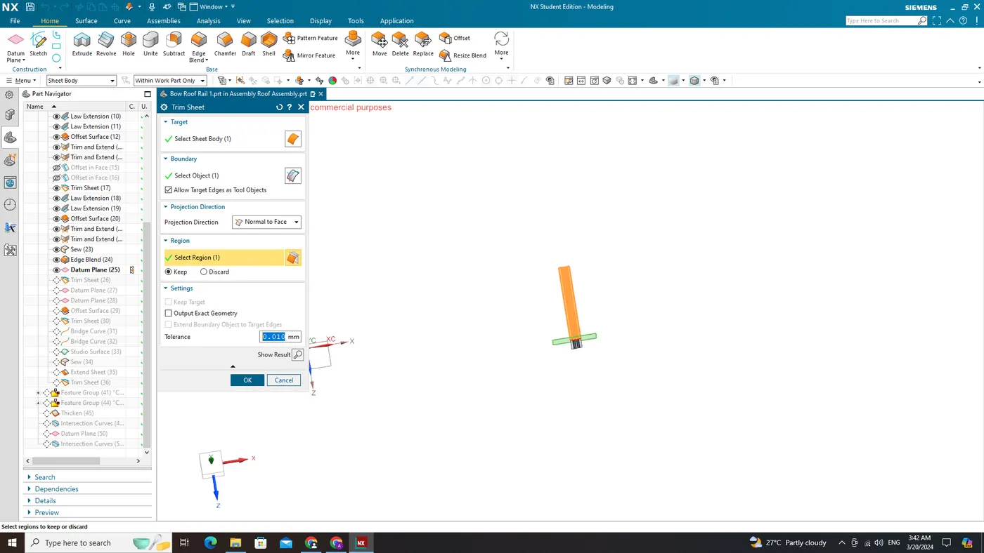
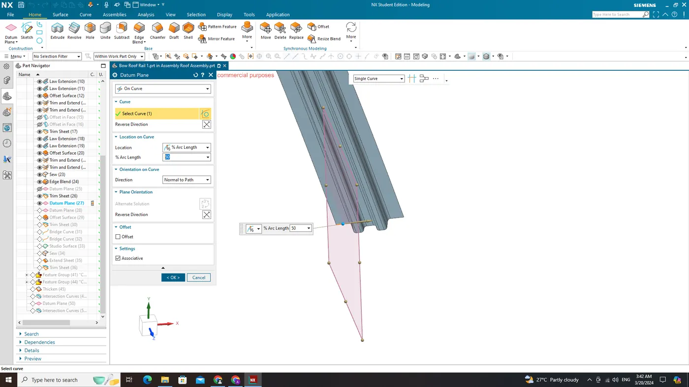
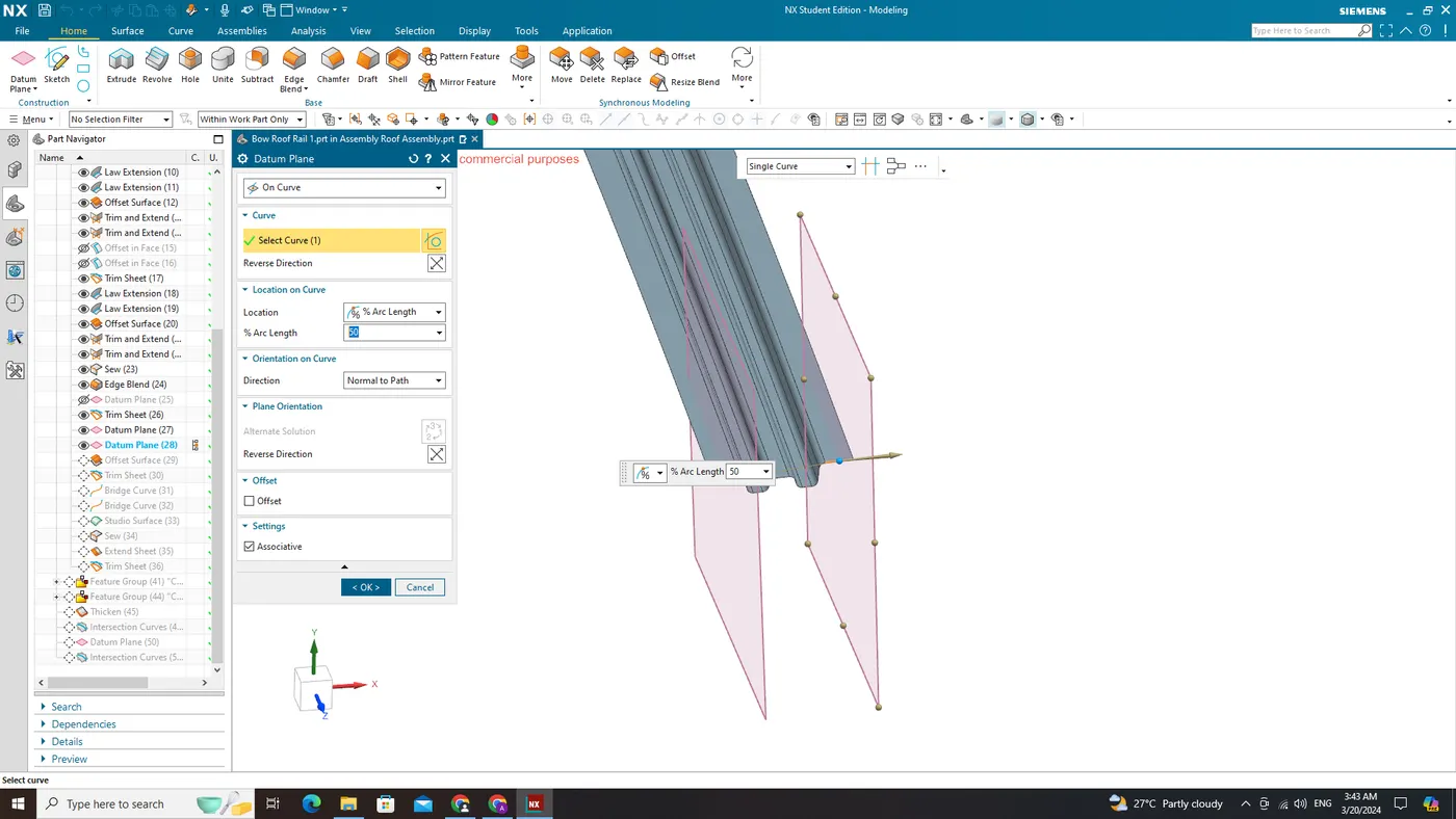
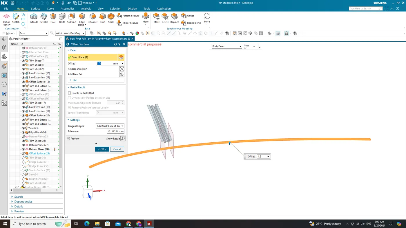
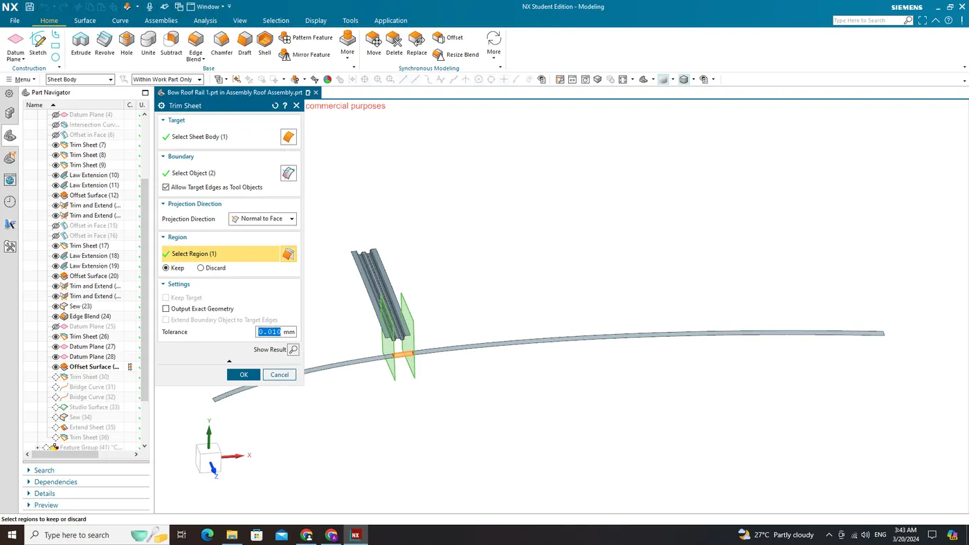
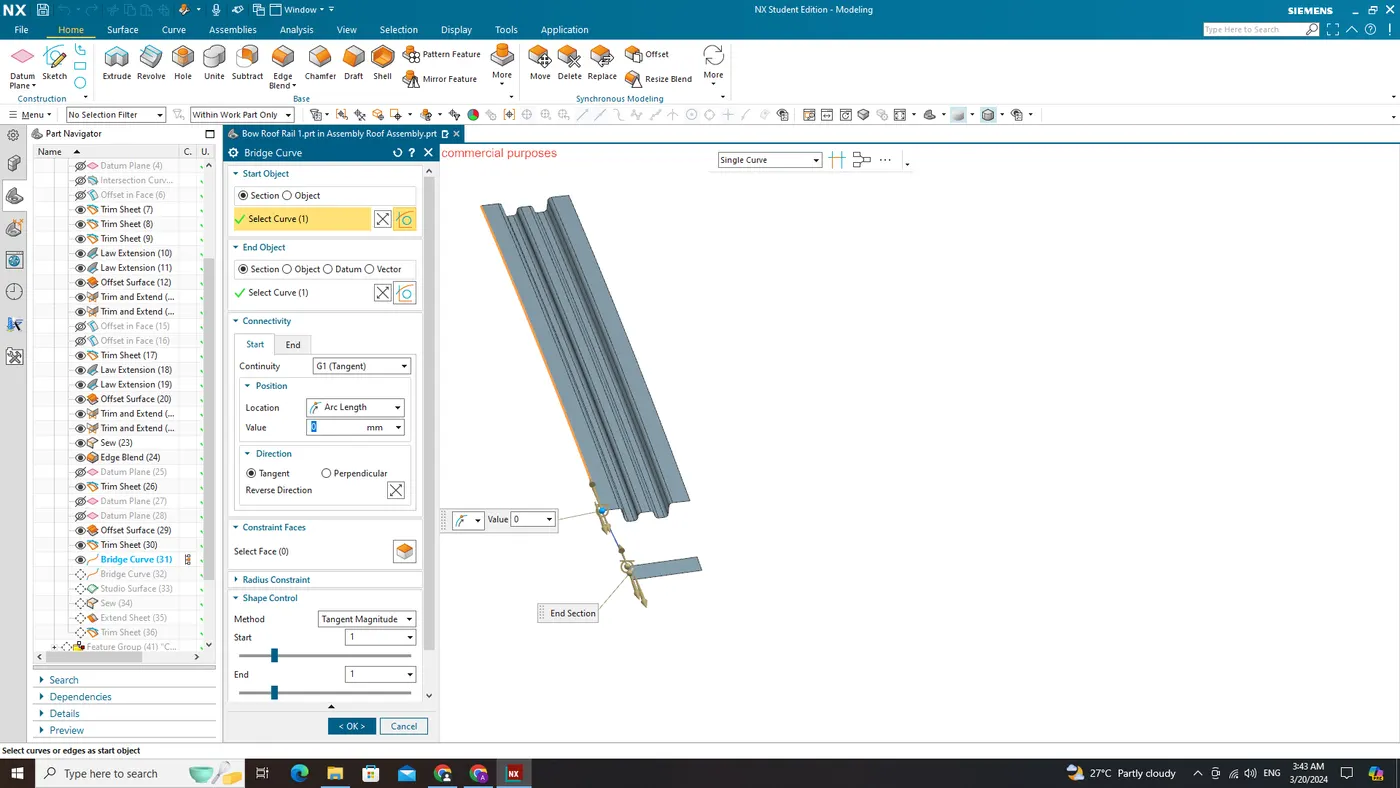
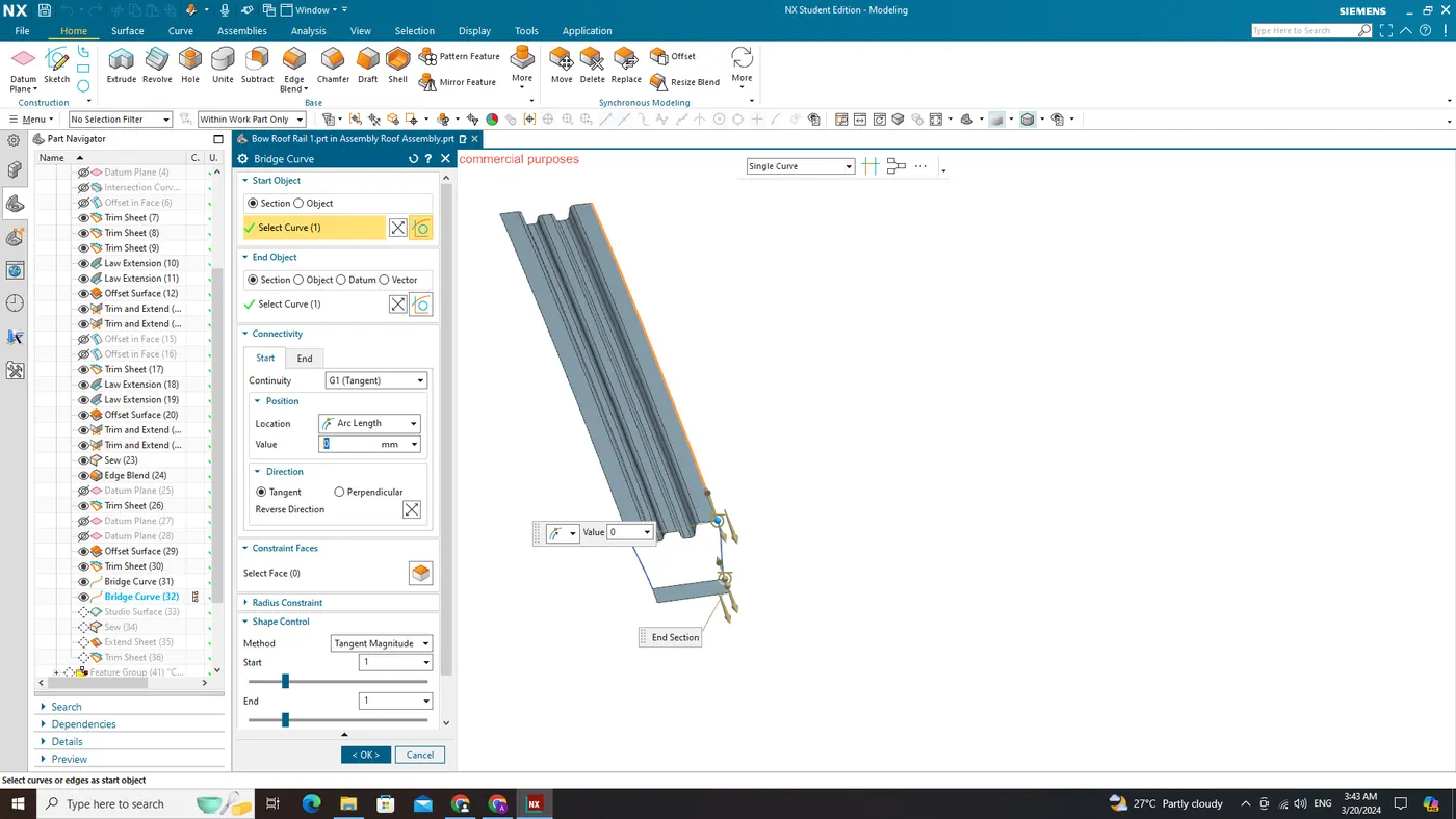
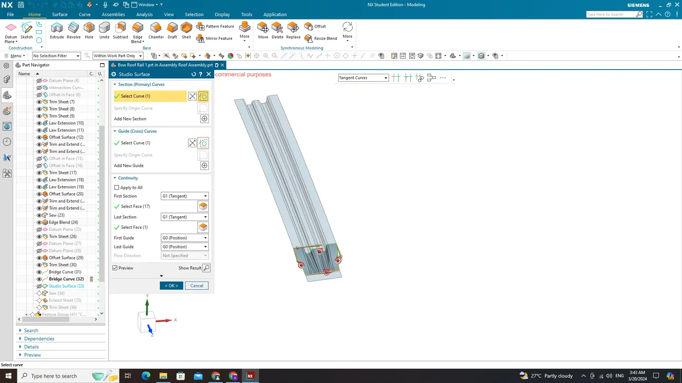
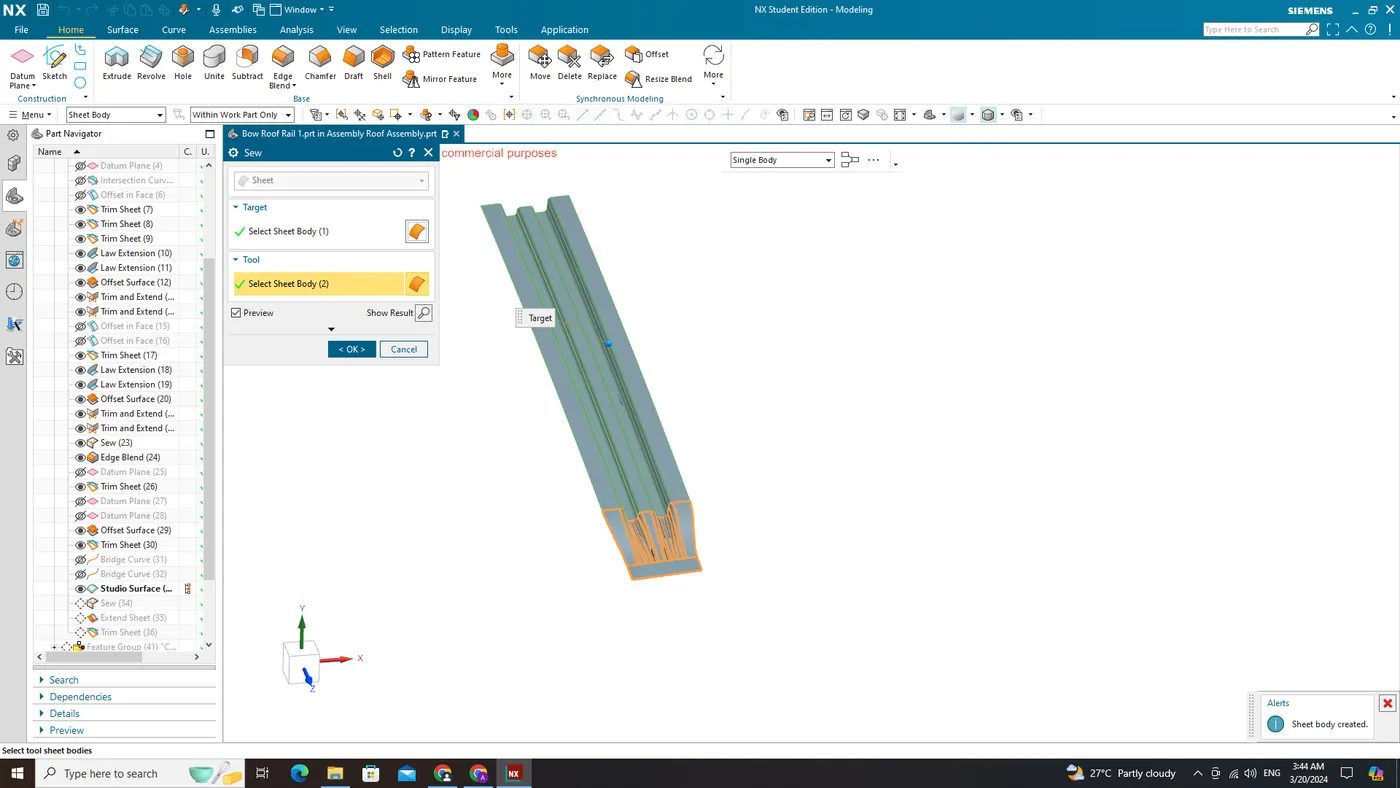
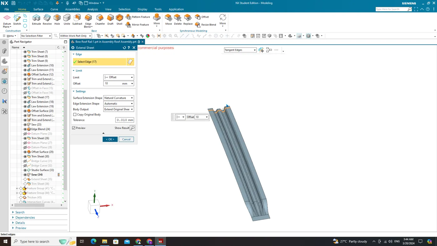
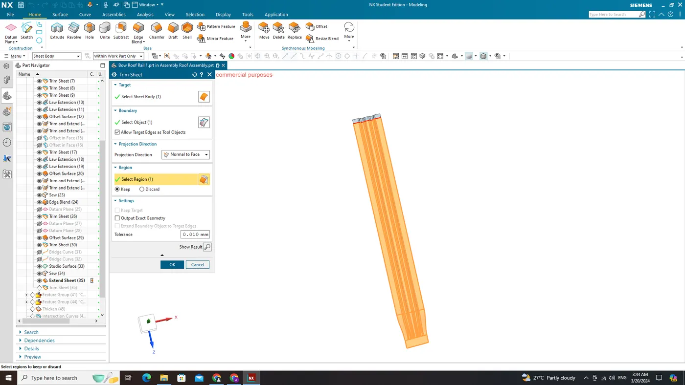
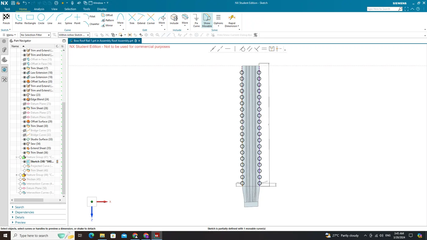
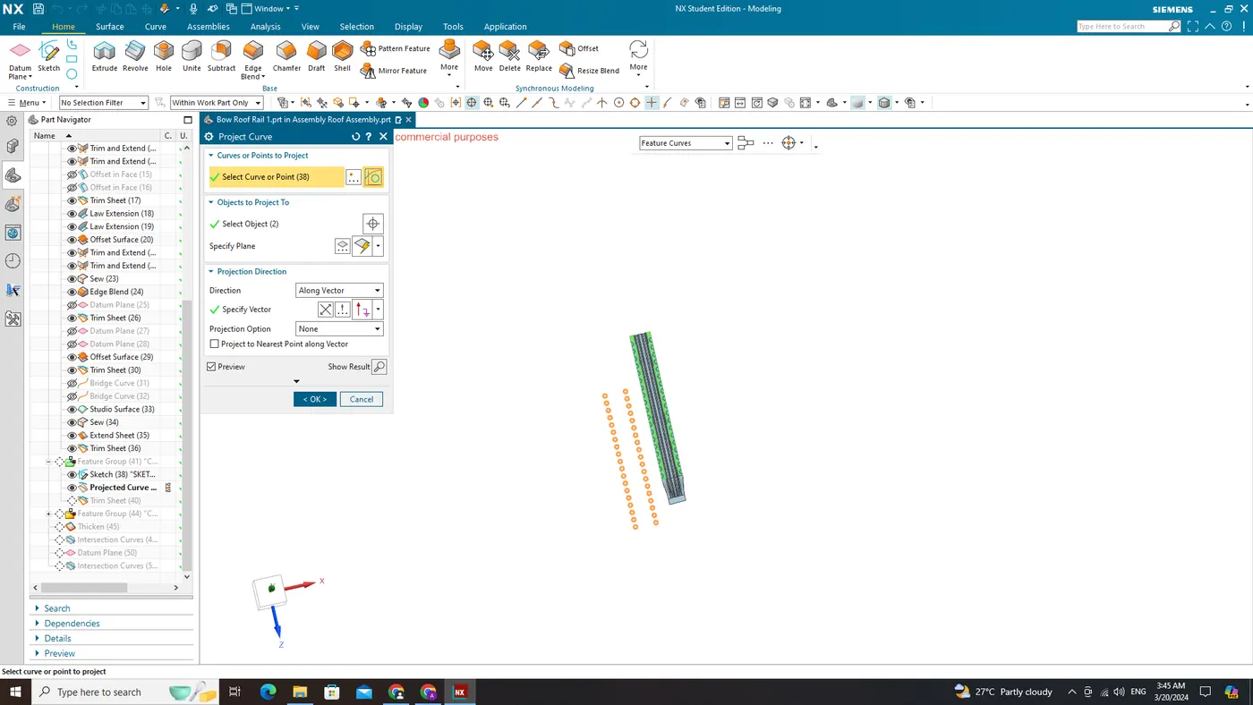
Bow Roof Rail 1
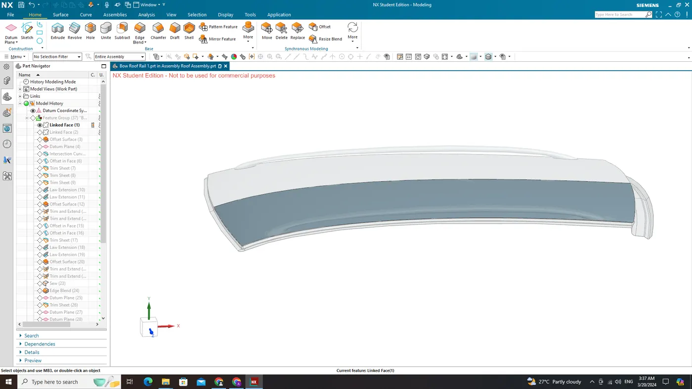
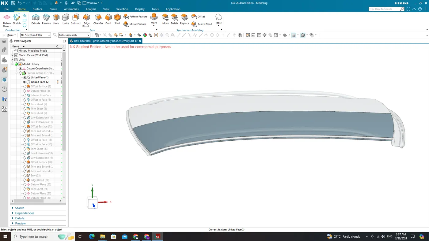
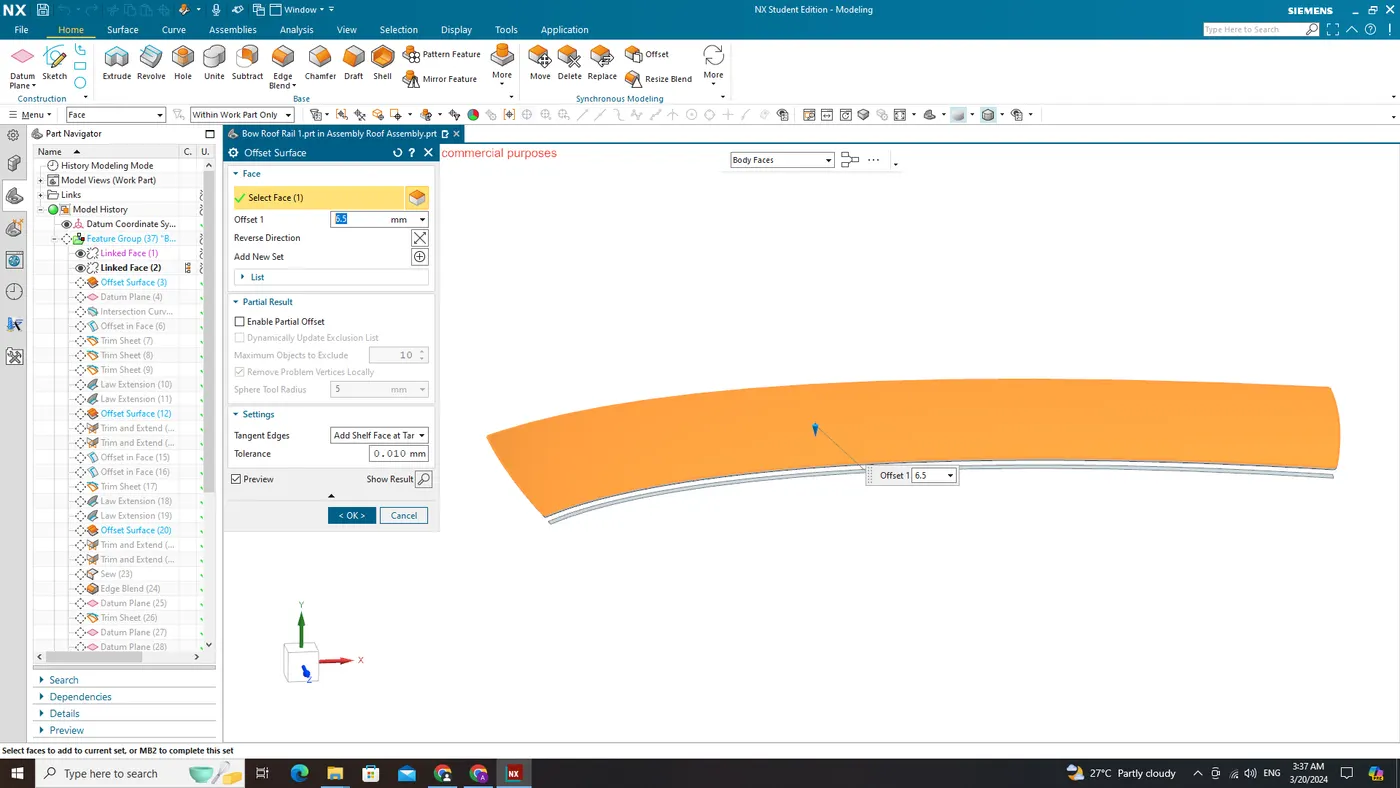
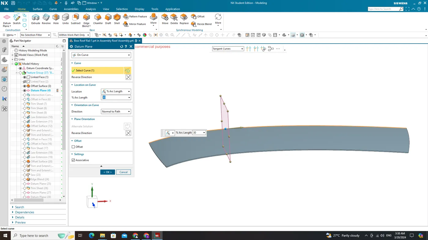
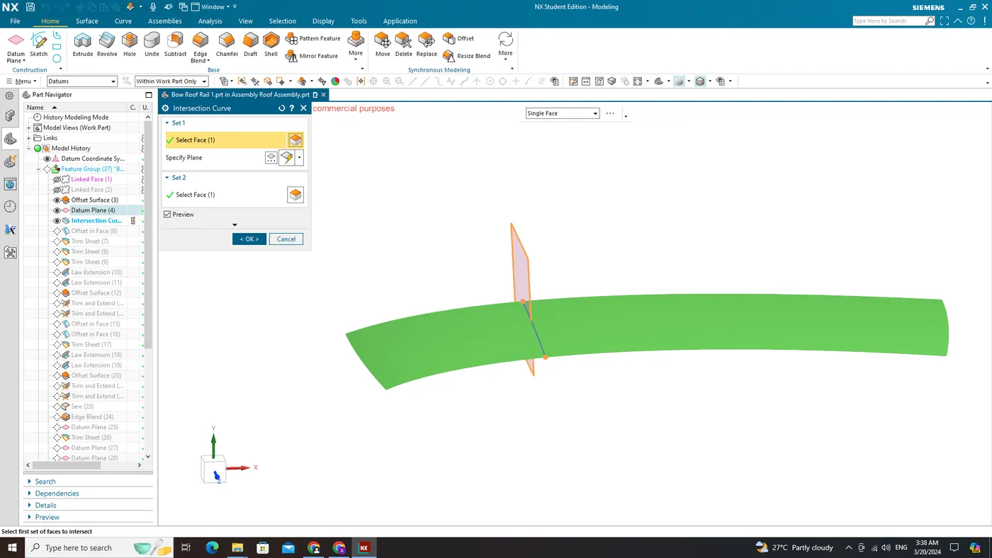
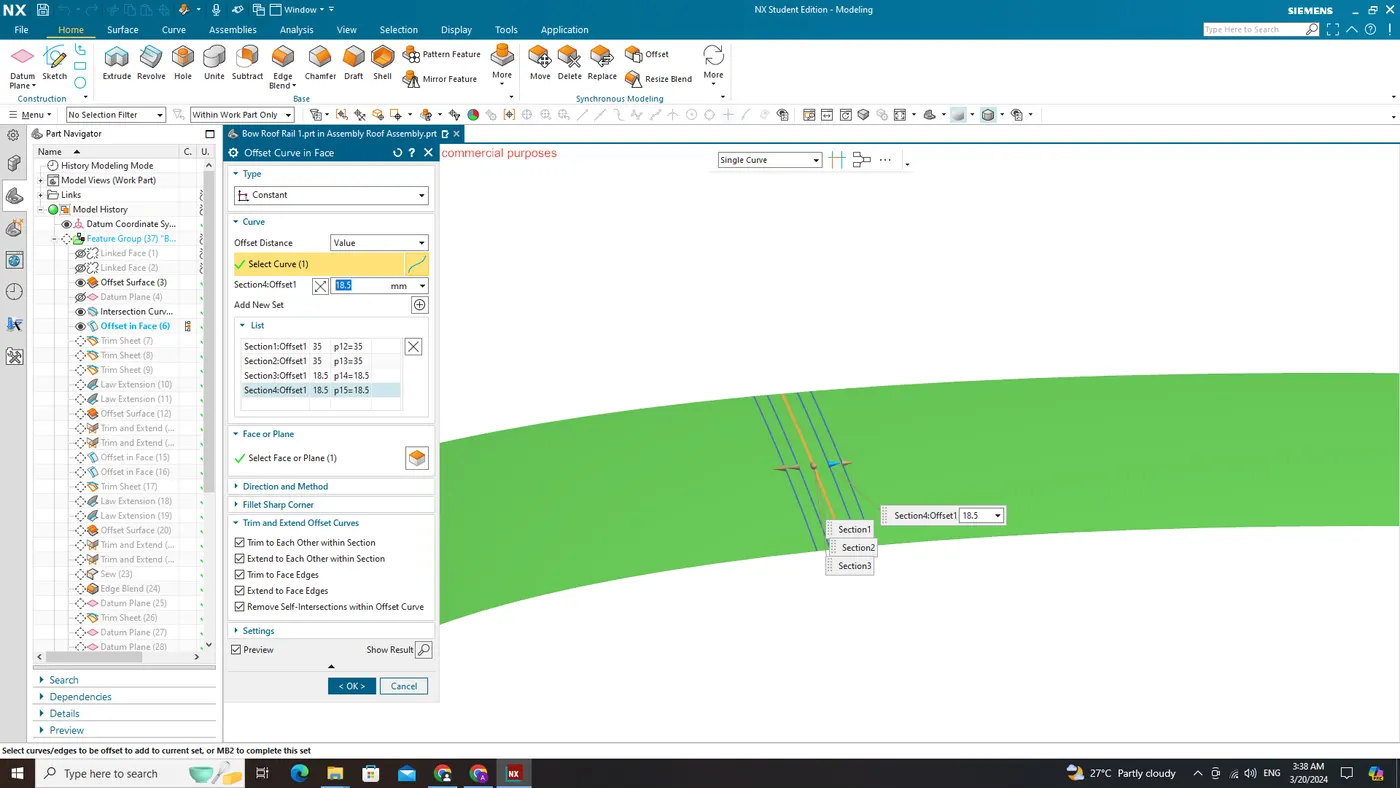
Mastic Sealants:
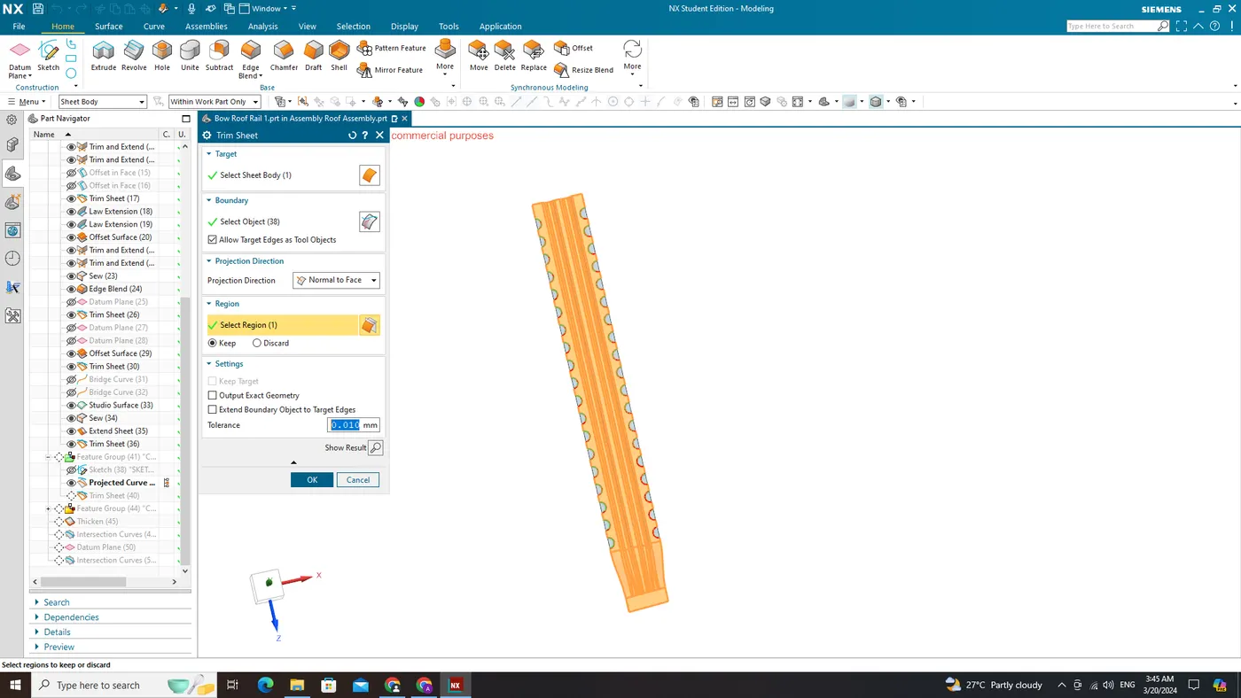
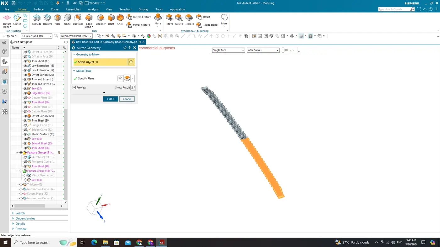
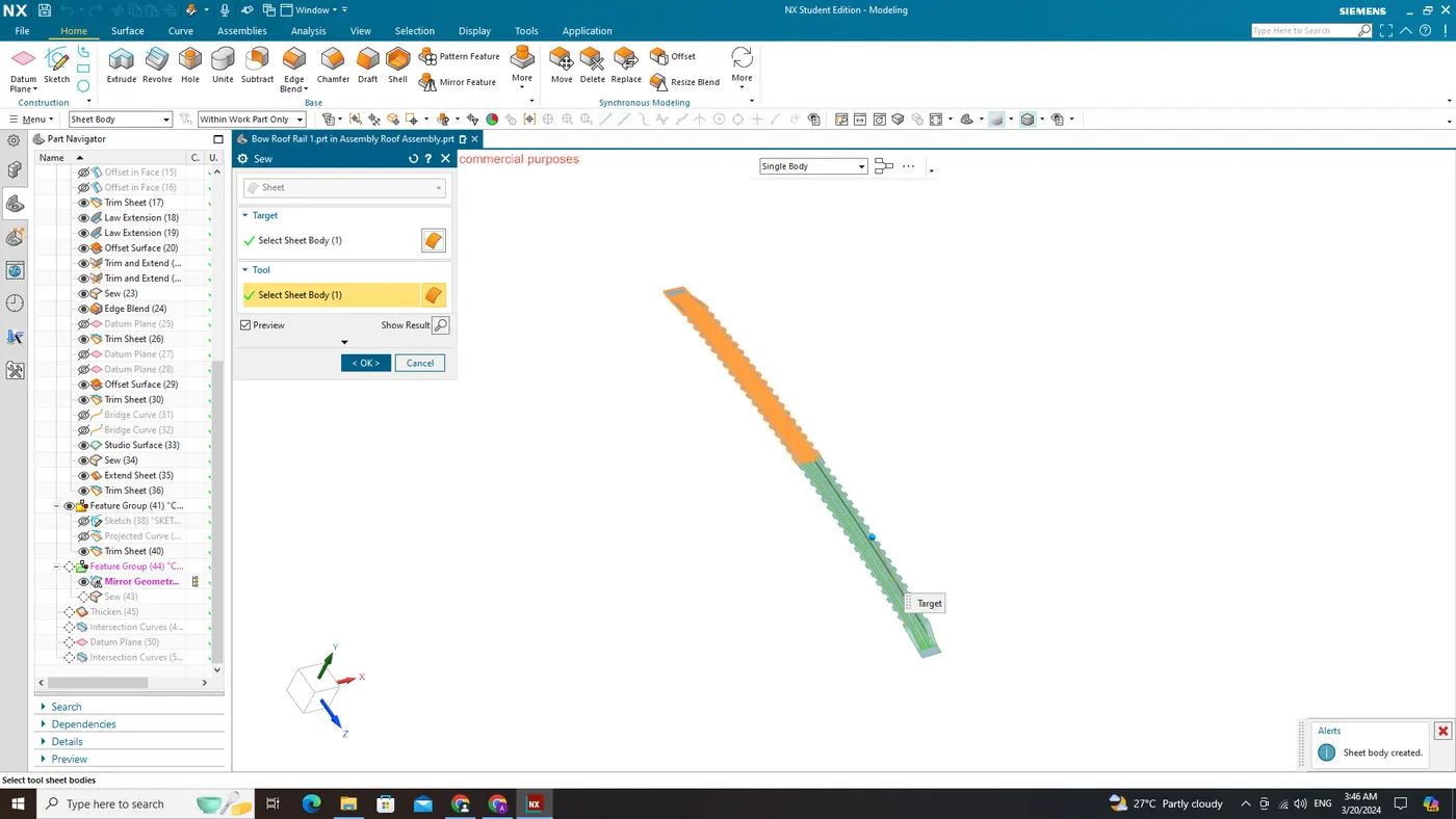
Thicken:
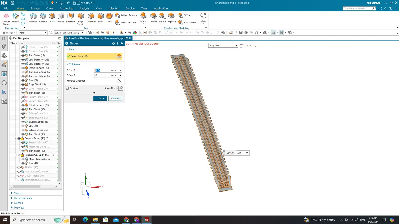
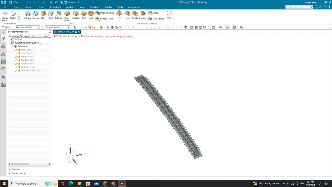
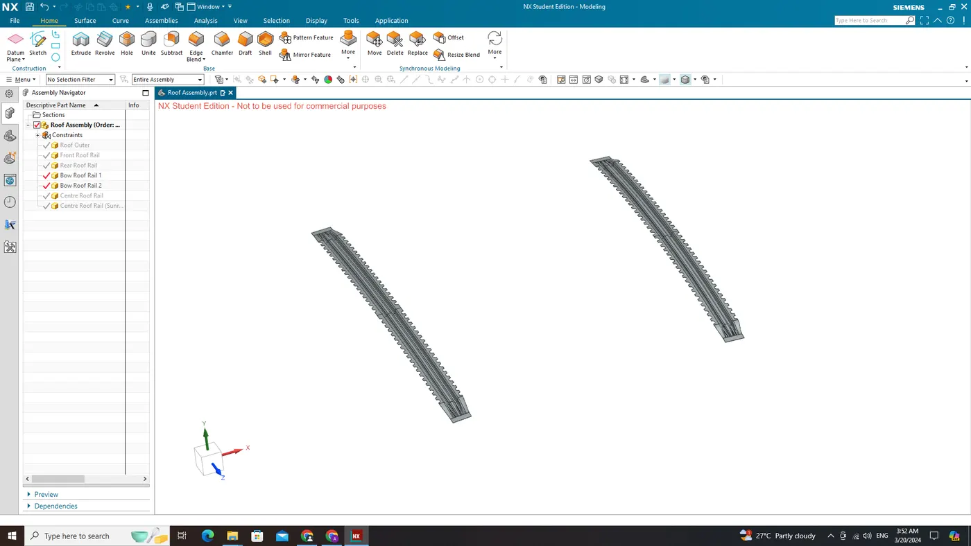
Bow Roof Rail 2
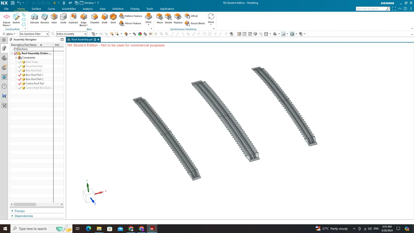
Centre Roof Rail
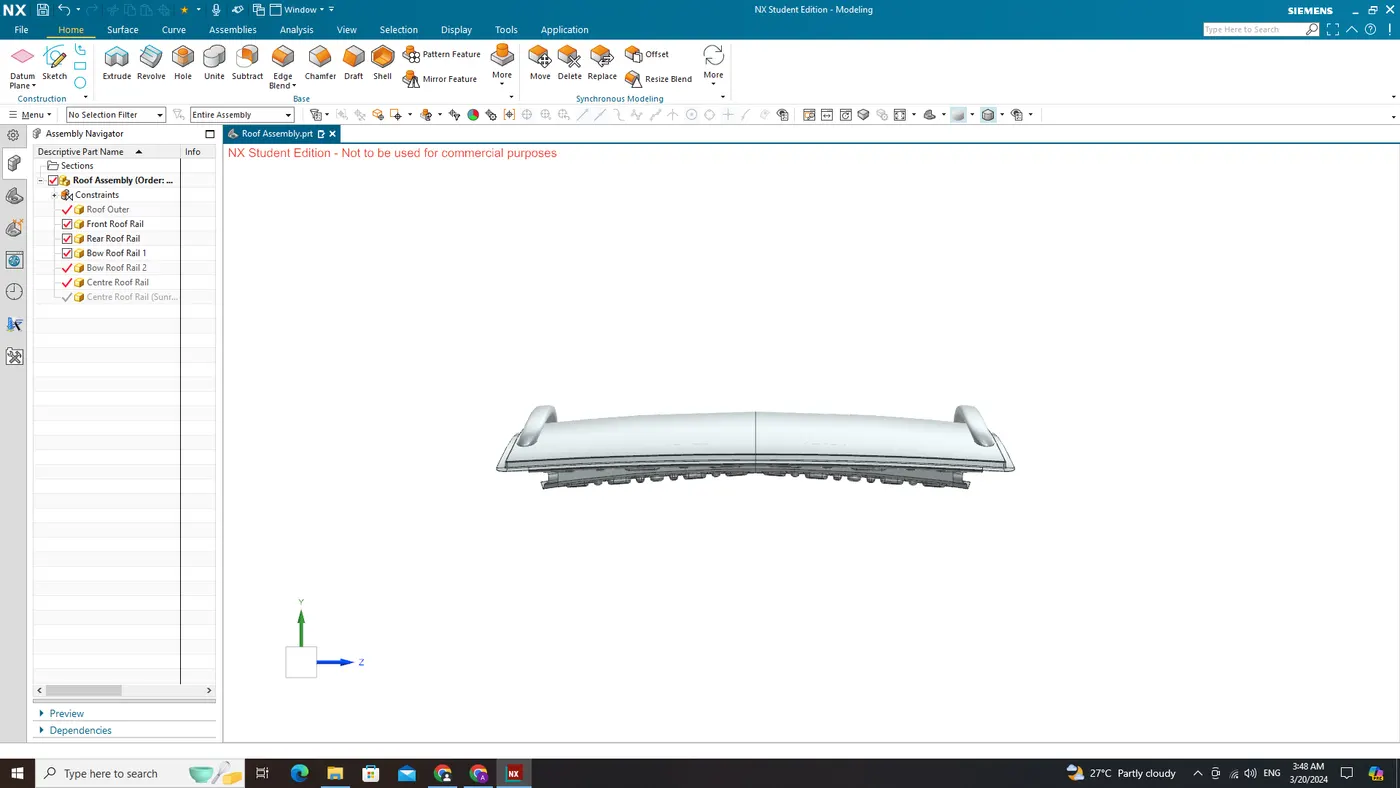
Views
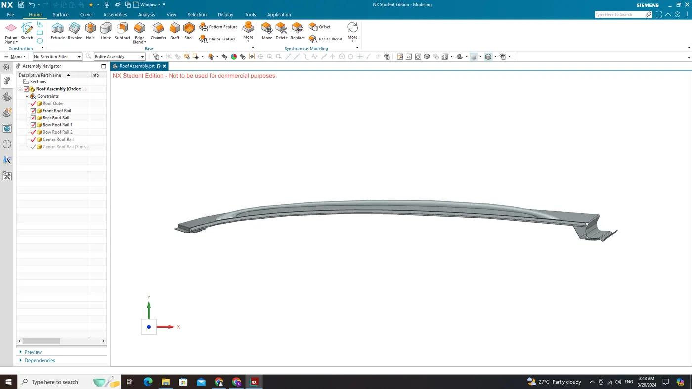
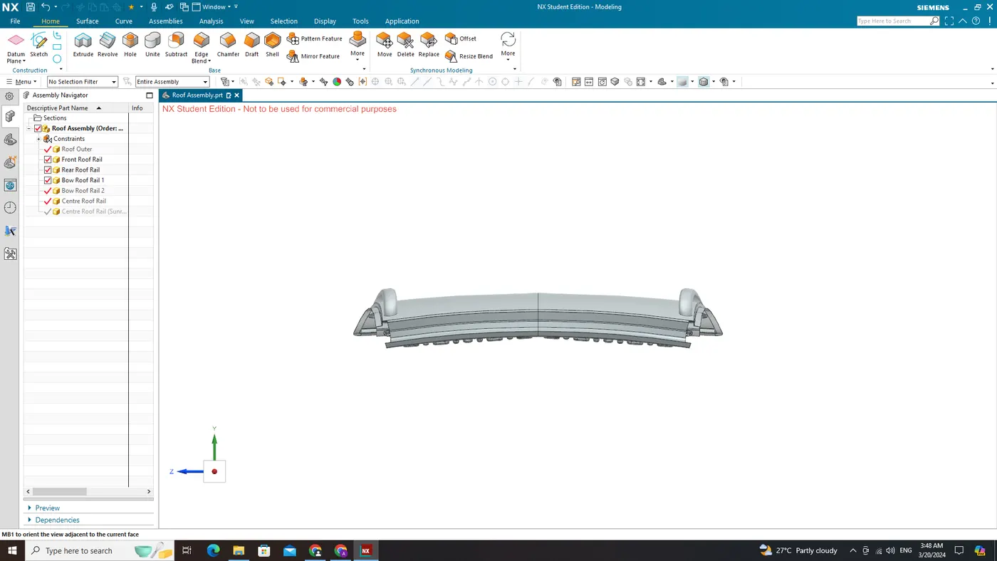
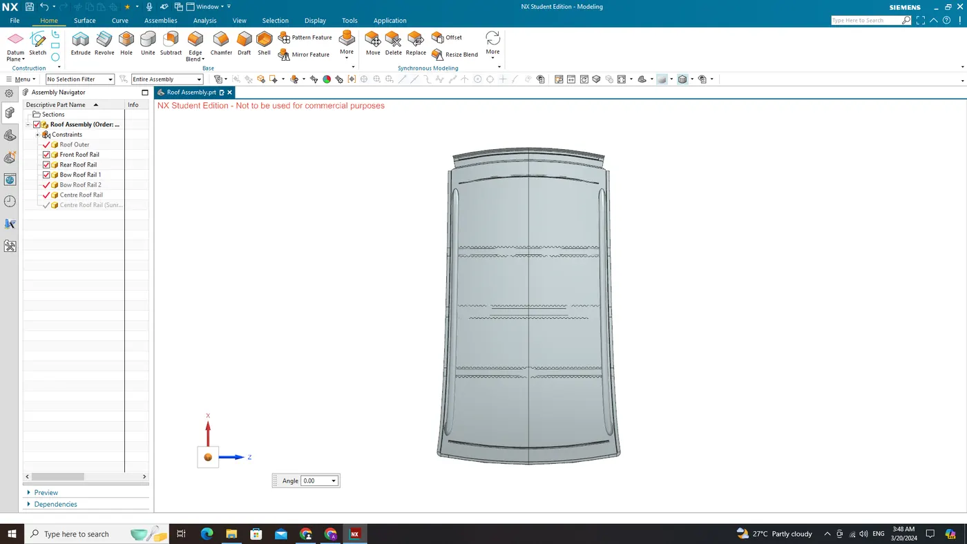
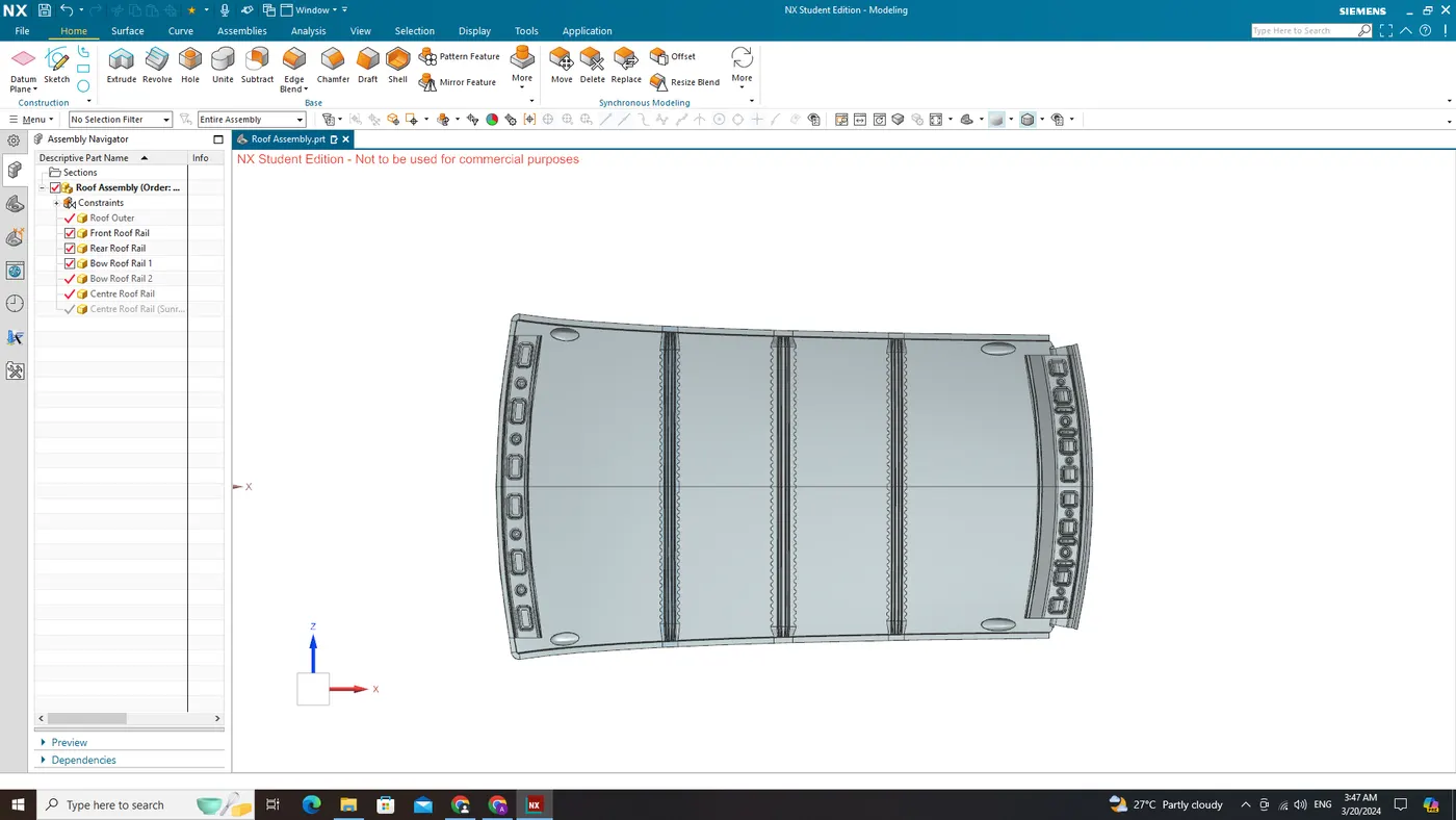
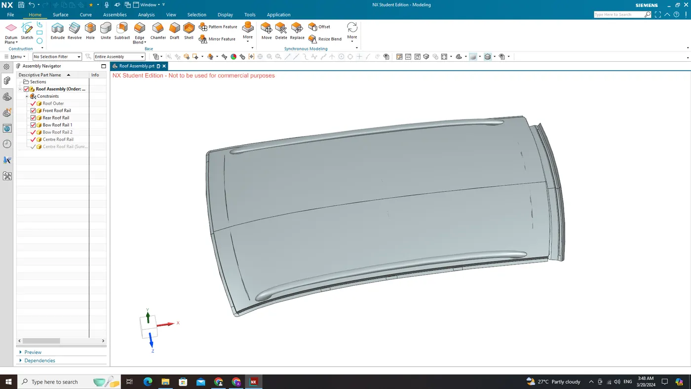
Calculations
Heat Distortion Criteria:
W = [1.73 x 10^(-3) x L] + [1.85 x 10^(-8) x (R^2)/t] + [ 1.10x10^(-3) x l] - 2.68
Judgement Condition : OK< 2.7
Where
L = Roof Length in X-Direction [mm] (Roof dimension in 0-Y)
R = 2(Rx*Ry)/(Rx+Ry)
R = Roof curvature
Rx = X curvature
Ry = Y curvature
t = Roof plate thickness [mm]
I = Bow Roof Span [mm]
L - Roof Length in X-Direction (0-Y)
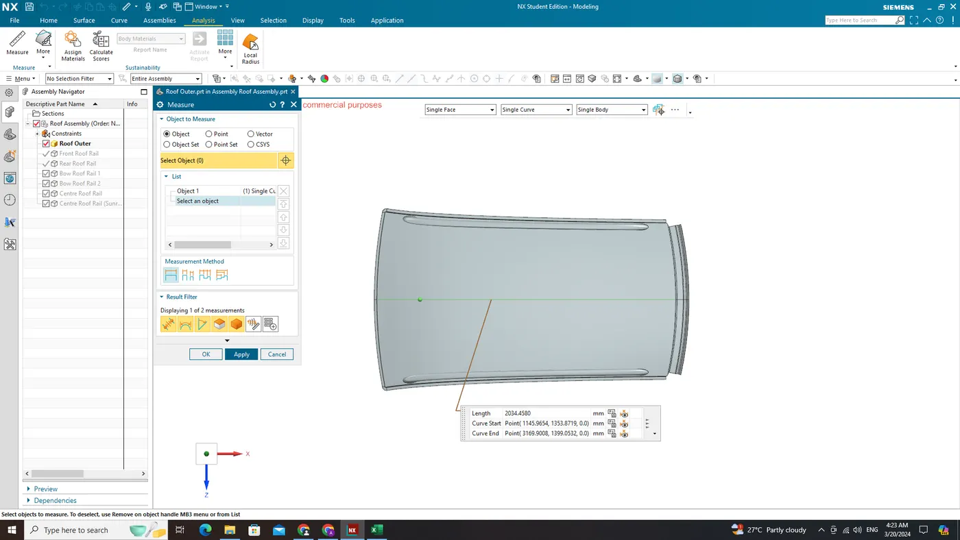
I - Bow Roof Span
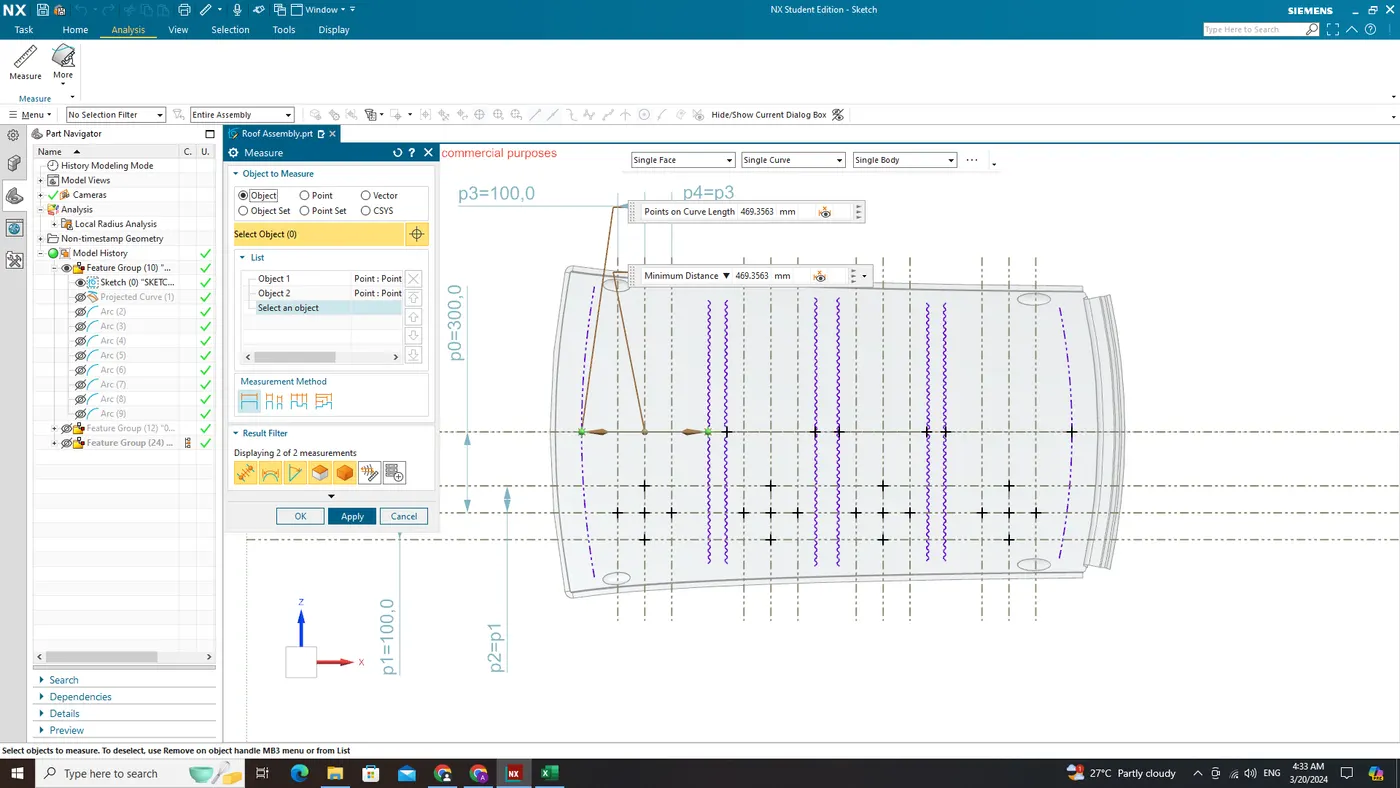
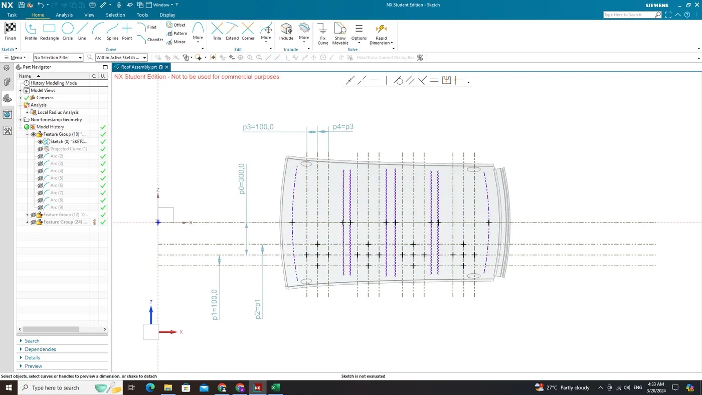
Rx & Ry (X & Y Curvature)
- From 0-Y axis, at -3Y about distance 300mm is drawn parallel on the perpendicular plane as shown in fig. after that 100 mm lines are offset to either side of -3Y line. Now centre lines are drawn between each adjacent roof rail edges respectively. Intersection points are marked on the sketch and exit the sketch. Make all geometry in construction lines except the points.
- Project the intersection points in the sketch to roof surface as shown in fig.
- Join the projected curves using arc curve and measure the minimum radius and linear dimension as follow & put into the formula to calculate “W”.
From the above fig, now project the points on the top of the Roof and draw the arc with the three points intersecting area as shown in below fig
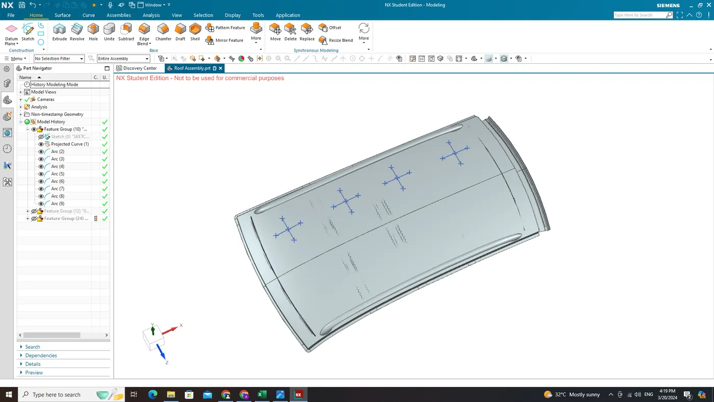
Find the Rx Curvature and Ry Curvature with the tool Simple Radius. For example shown in fig below
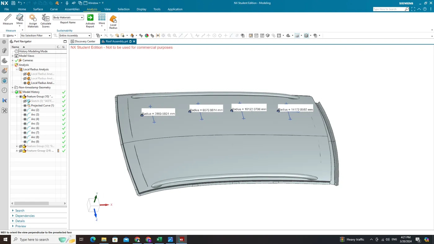
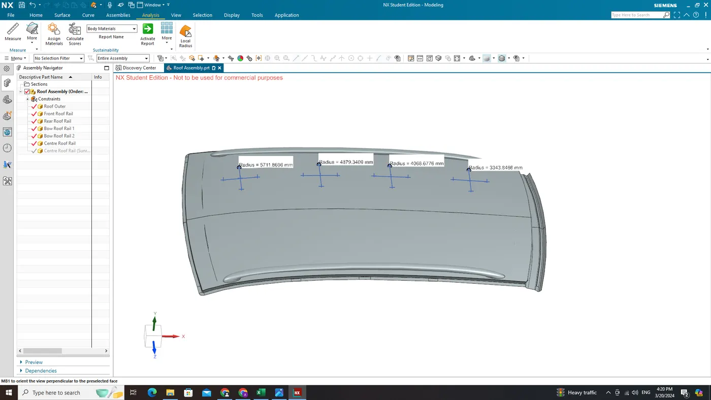
Apply the values in the formula of Heat Distortion Criteria.
The calculations are perfomed in MS Excel below,
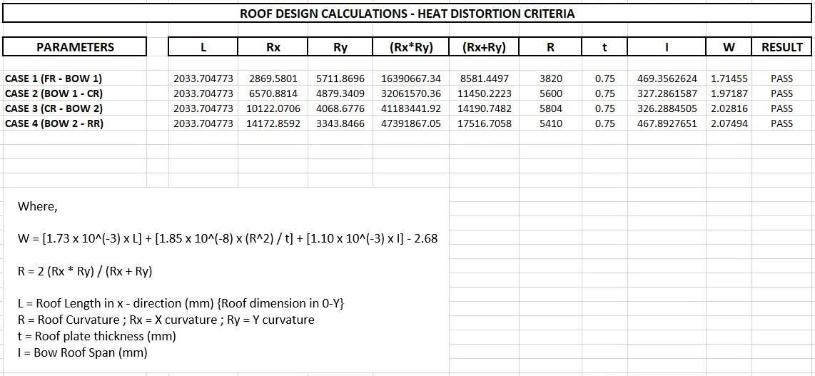
From the above calculations and the table we find that all values of 'W' are less than 2.7 (i.e., <2.7), so the current positioning of the bow roof rails are good in state as per in design and passed the judgement condition.
Snow Load Prediction
Qr = [Iy x t2] / [α x s x [(Rx + Ry)/2]2 x 10-8]
Where,
α = My x Lx2 x 10-12 , My = Y(Ly-Y)
Judgement condition = Qr ≥ 3.1 & 250 ≤ s ≤ 380
t = Roof plate thickness [mm]
Ly = Distance between the front and rear roof Rails on the Vehicle along with 0Y[mm]
Length of Roof panel with the center point between Roof rail Front /Rear as the reference point of the front and the rear.
Lx = Distance between the Left and Right end of the roof on the Roof BOW [mm]
Width of the roof panel exposed on the surface.
Y = Distance front Front Roof Rail to Roof BOW[mm]
s = Distance for which Roof BOW bears divided load [mm]
s = L1/2 + L2/2
Iy = Geometrical moment of inertia of Roof BOW (Y cross-section )[mm4]
Rx = Lateral direction curvature radius of roof panel Y cross-section on Roof BOW [mm]
Roof panel curvature Radius of the Length Lx in Front view
Ry = Longitudinal Direction curvature radius of the Roof panel X cross-section on Roof BOW [mm]
Roof panel X curvature radius of length s in Side view
Rx & Ry (X & Y Curvature)
- At 0-Y axis on perpendicular plane to roof as shown in fig. draw 100 mm lines offset to either side of 0Y axis line. Now centre lines are drawn between each adjacent roof rail edges respectively. Intersection points are marked on the sketch and exit the sketch. Make all geometry in construction lines except the points.
- Project the intersection points in the sketch to roof surface as shown in fig.
- Join the projected curves using arc curve and measure the minimum radius and linear dimension.
- Project the intersection plane bow roof and centre roof rail on the horizontal plane to find the moment of inertia of the respective section to find Iy values.
- Put all the linear and radial dimension in following formula to calculate Qr Value.
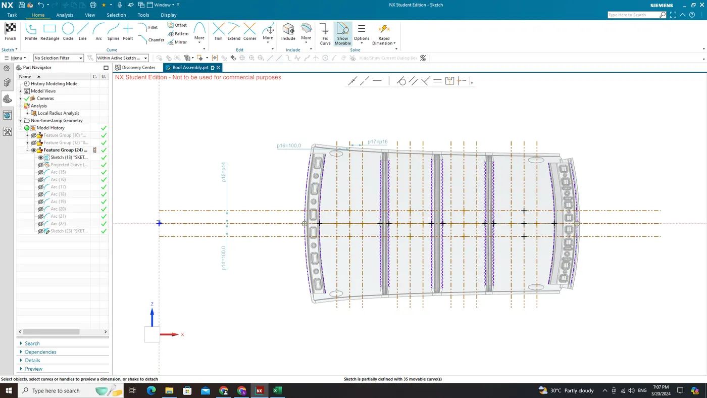
From the above fig, now project the points on the top of the Roof and draw the arc with the three points intersecting area as shown in below fig,
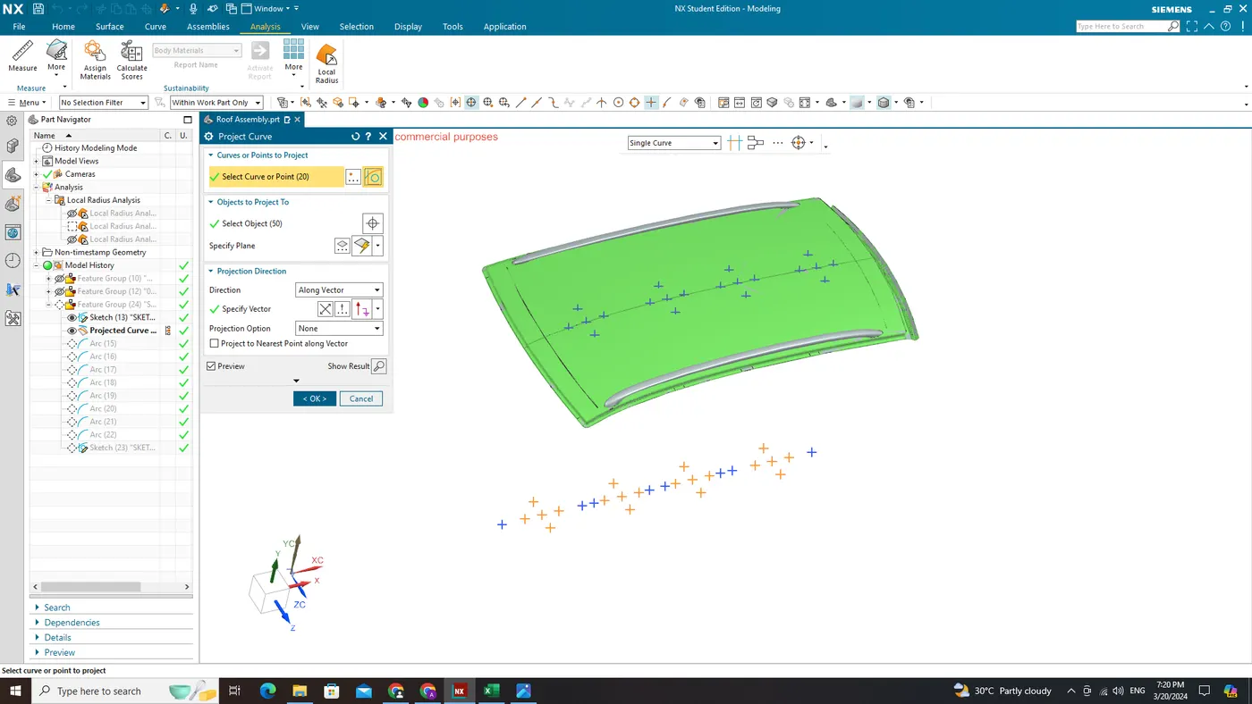
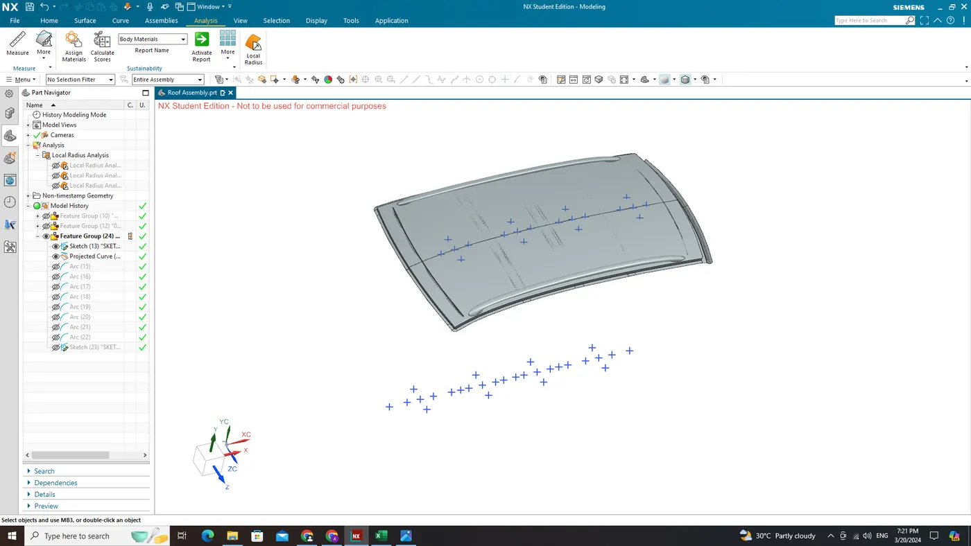
Find the Rx Curvature and Ry Curvature withe the tool Simple Radius. For example shown in fig below
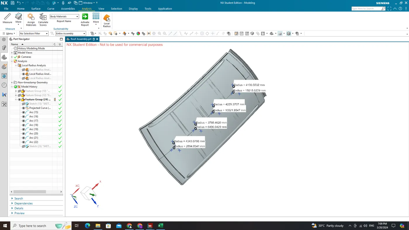
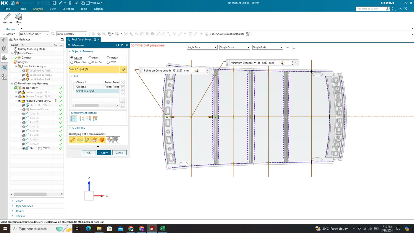
Lx - Distance between the Left and Right end of the roof on the Bow Roof
Lx values for each case should be taken as shown in fig,
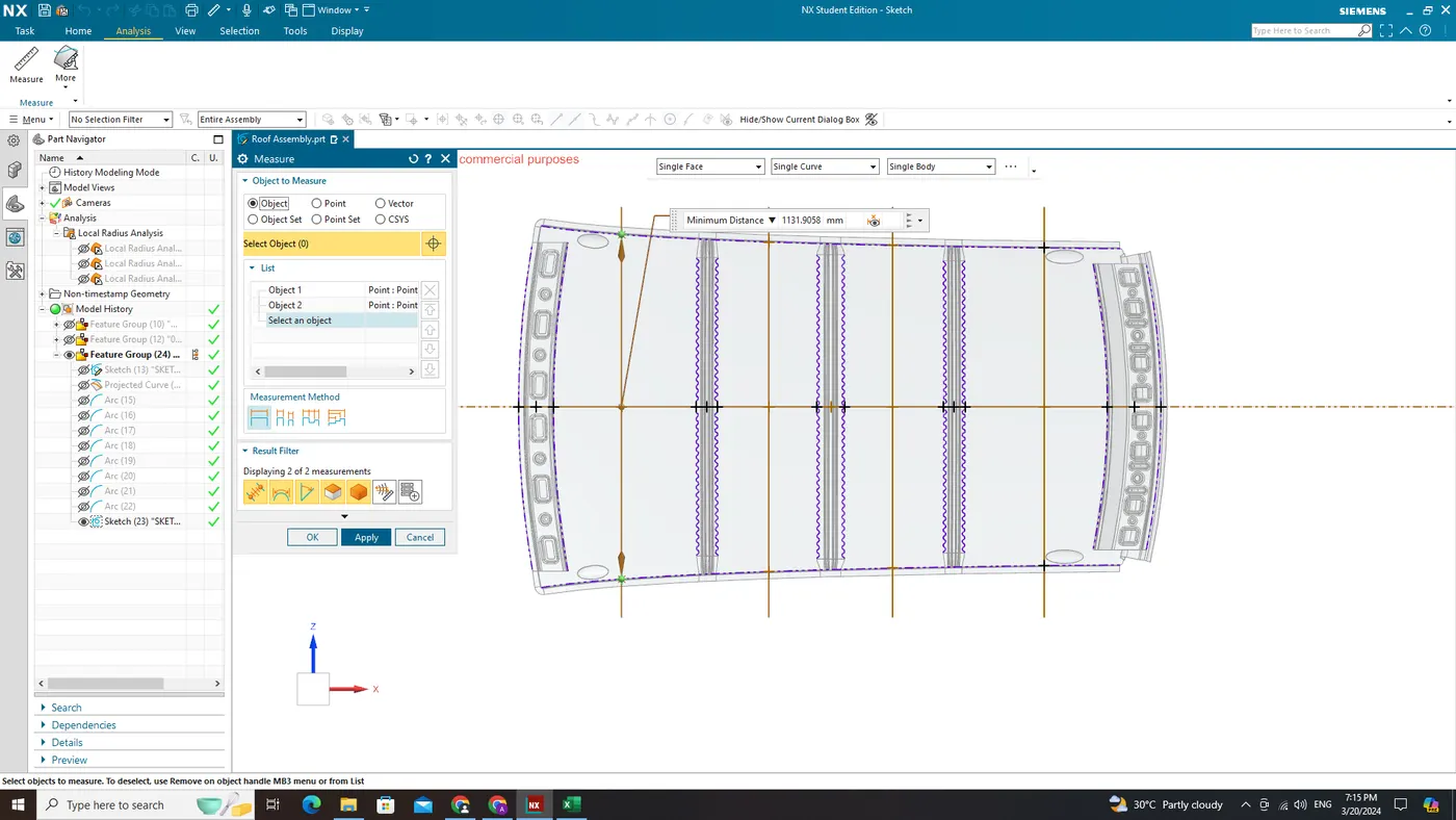
Ly - Distance between the centre of front and rear roof Rails on the Vehicle along with 0Y
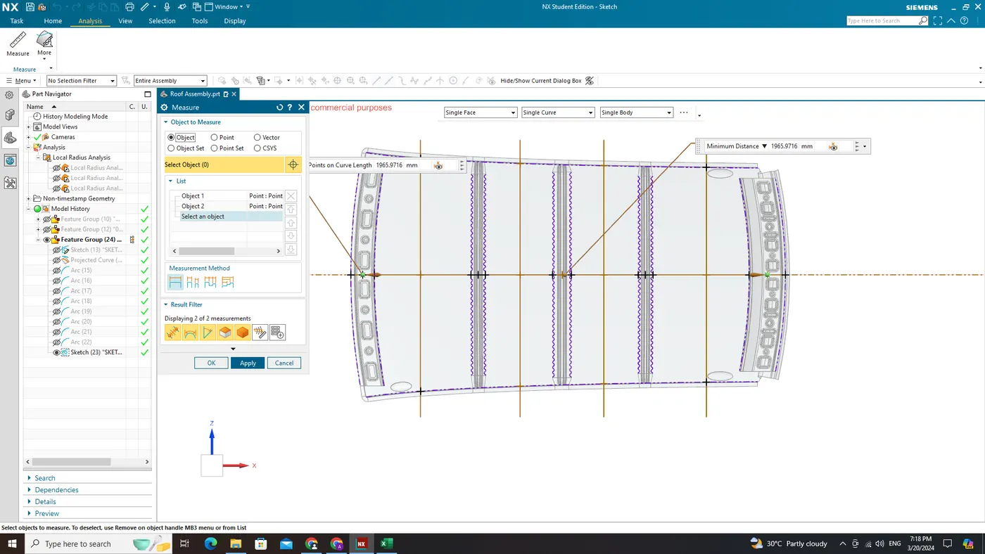
Y - Distance from Front Roof Rail to each centre point Bow Roof in 0-Y
Y value of each case you have to measure the distance from centre of your front roof rail to the centre of the respective bow roof.
Geometrical Moment of Inertia for the Roof Rails
1. Bow Roof Rail 1
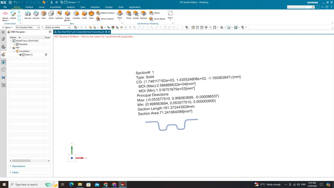
2. Bow Roof Rail 2
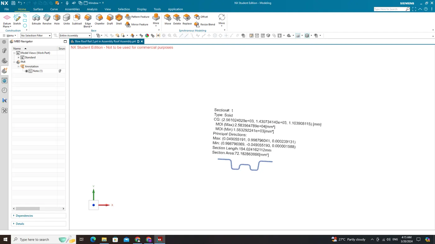
3. Centre Bow Roof Rail
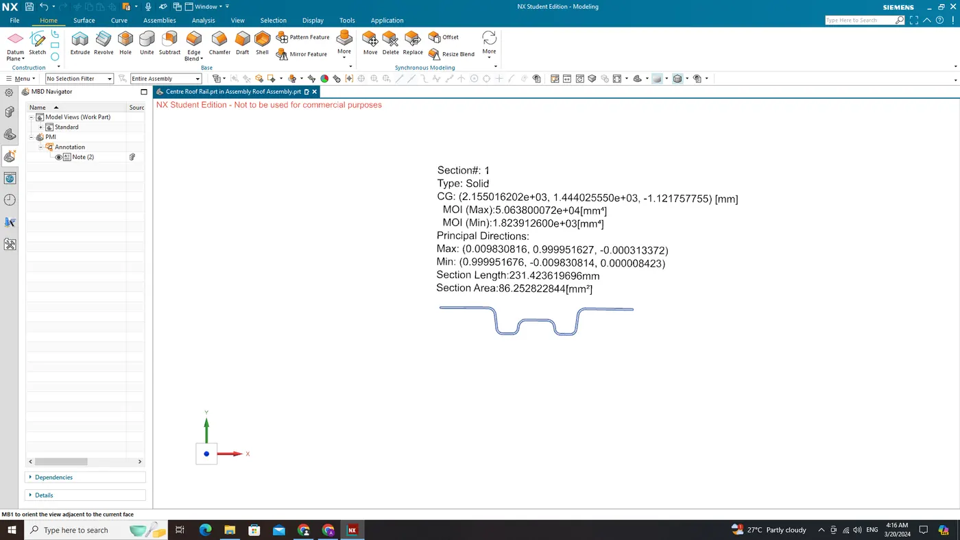
L1 and L2 values for each case
Apply the values in the formula of Snow Load Prediction.
The calculations are perfomed in MS Excel below,
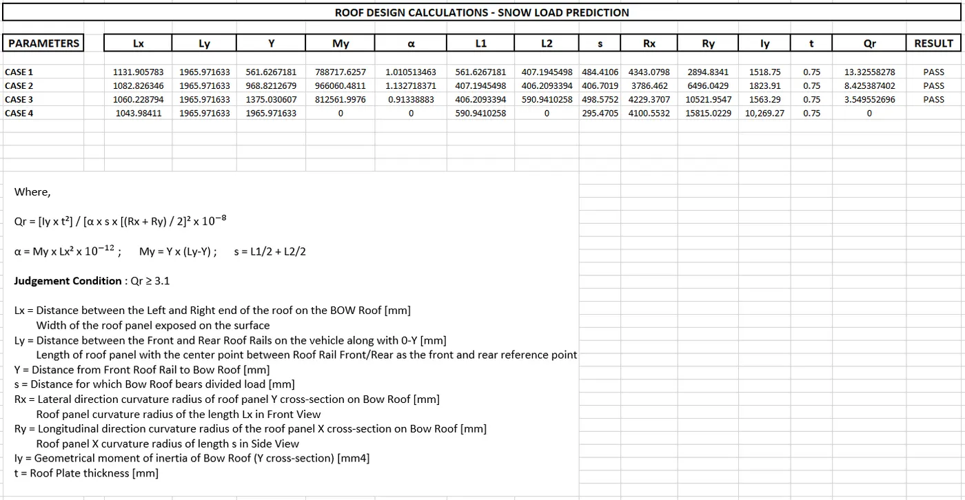
From the above calculations and the table we find that all values of 'Qr' are greater than/equal to 3.1 (i.e., ≥ 3.1), so the current positioning of the bow roof rails are good in state as per in design and passed the judgement condition.
Draft Analysis:
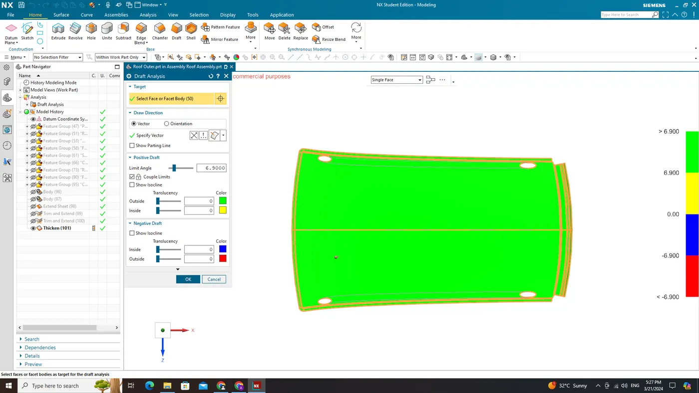
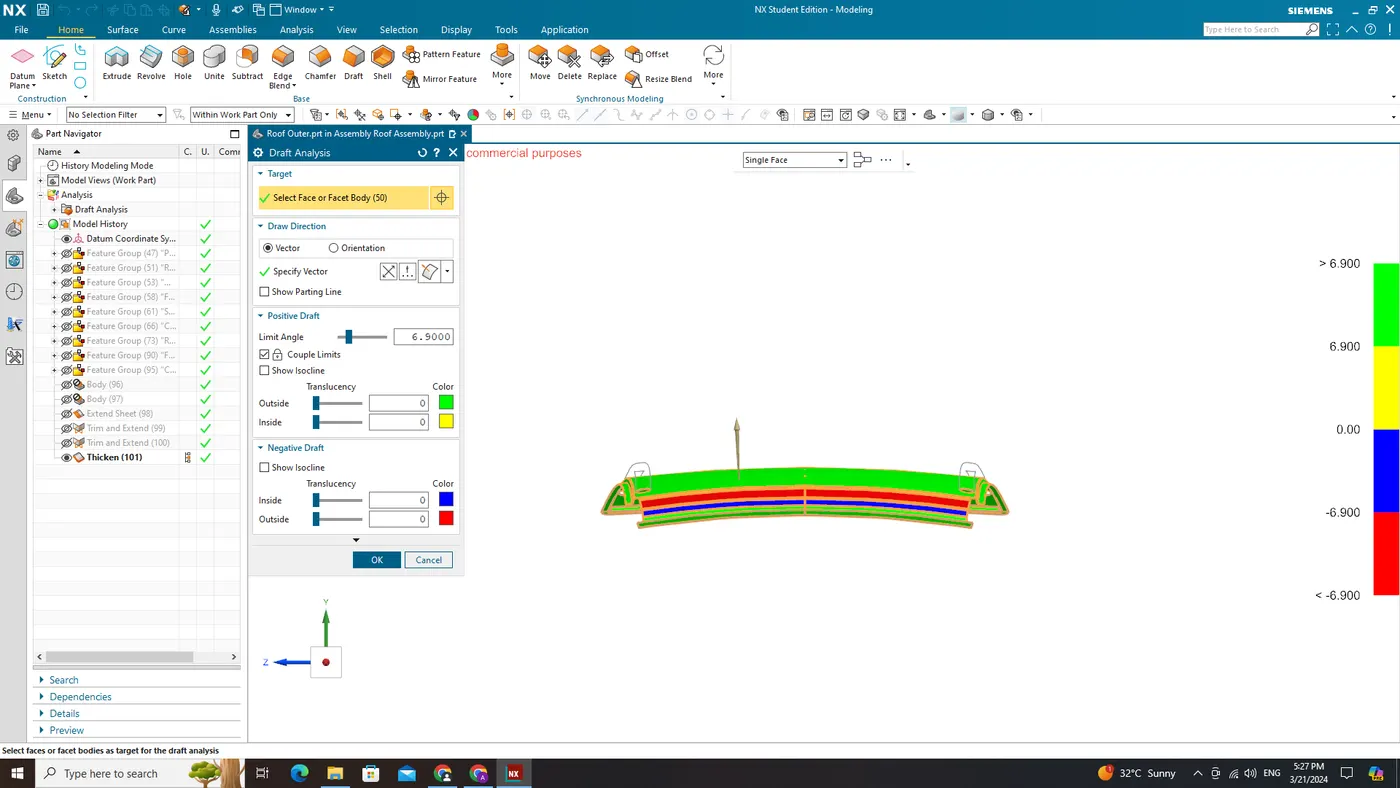
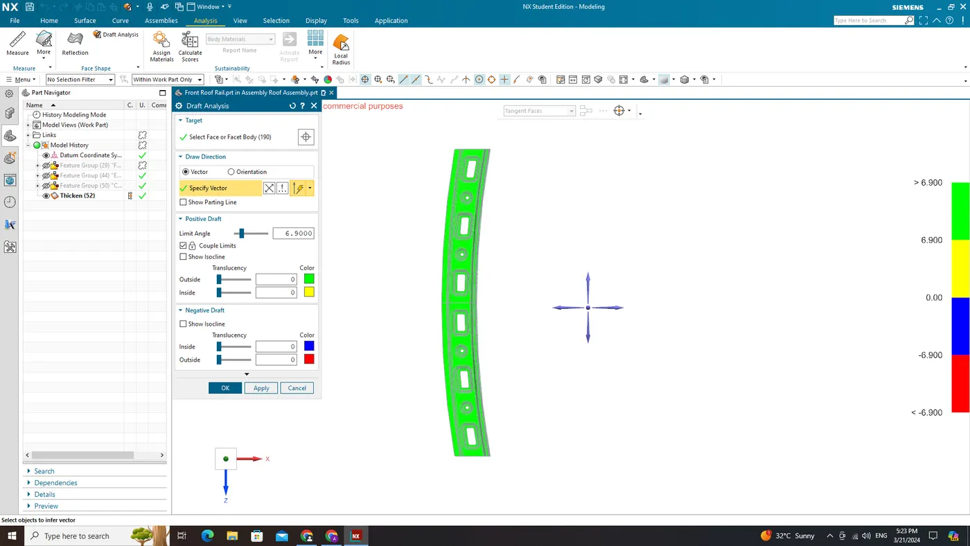
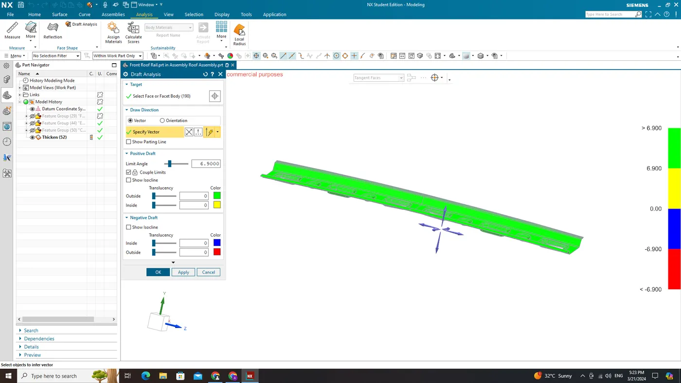
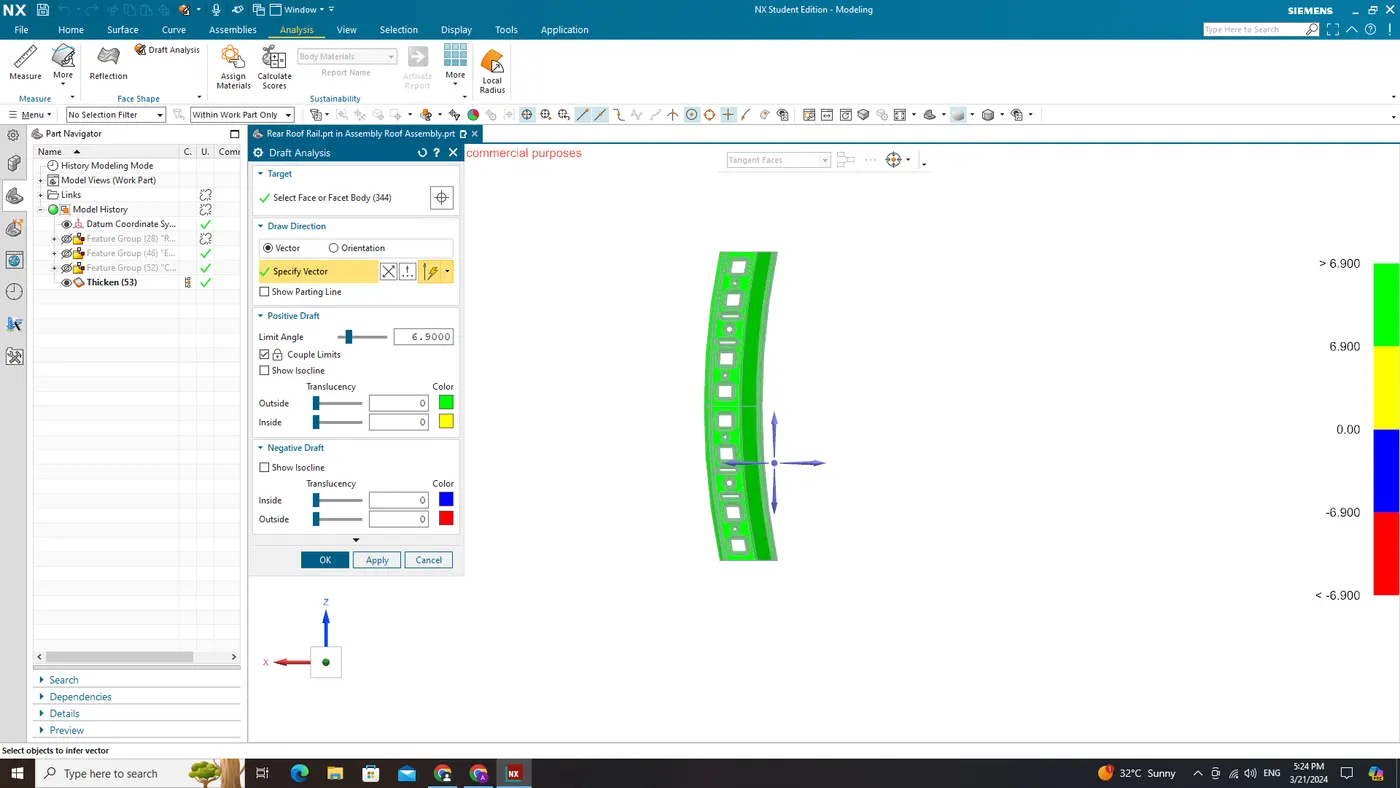
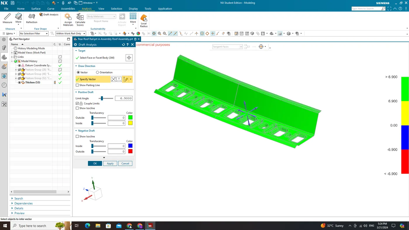
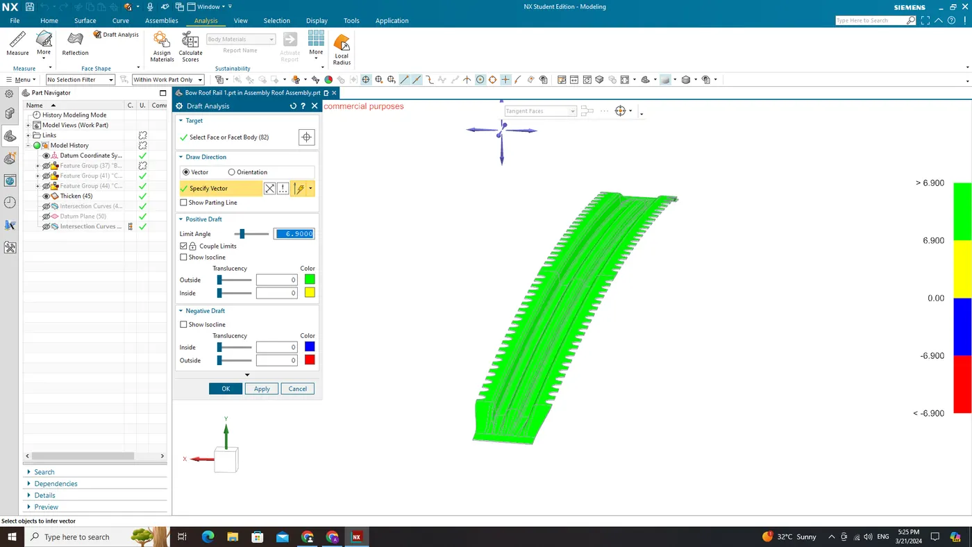
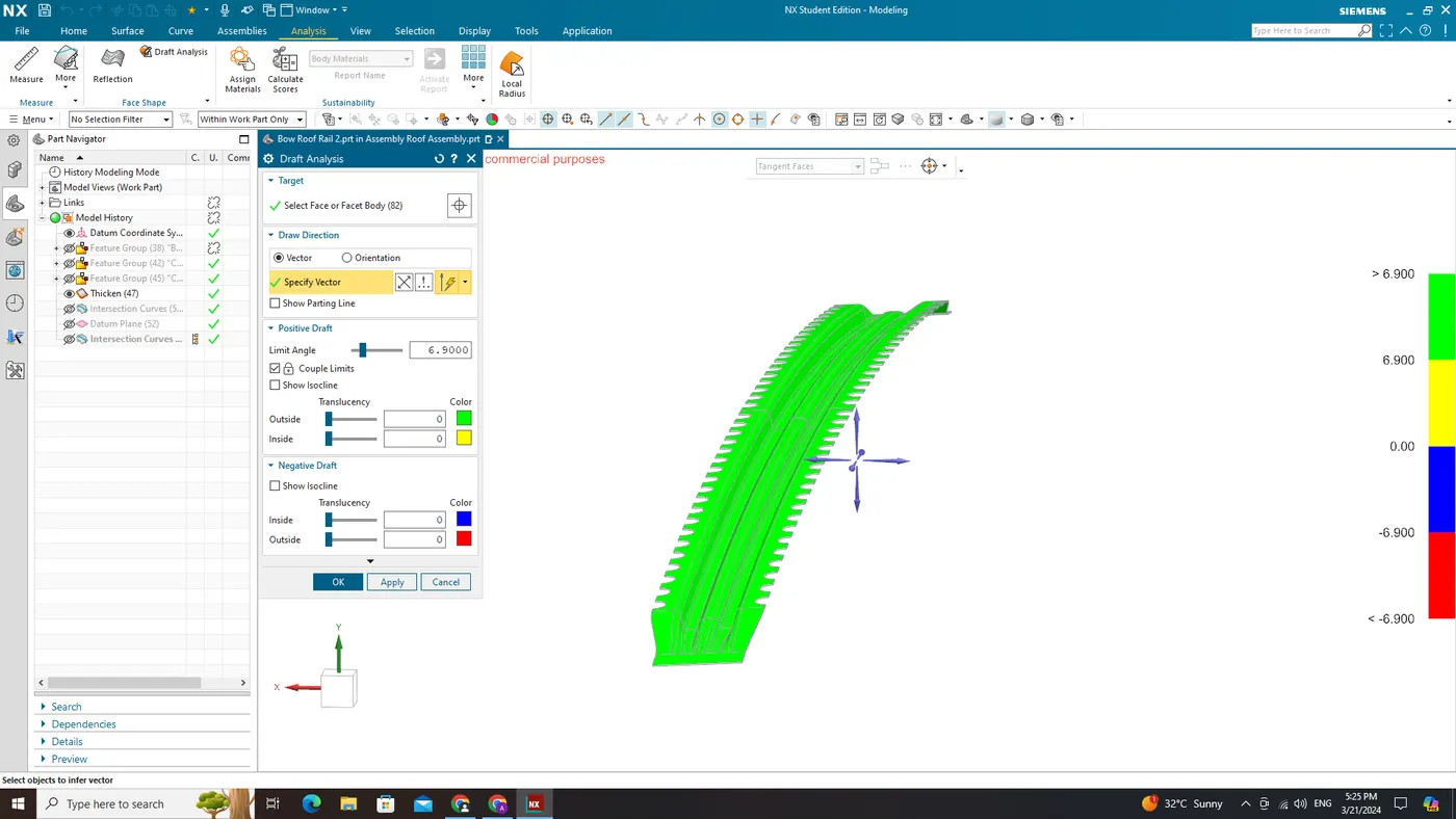
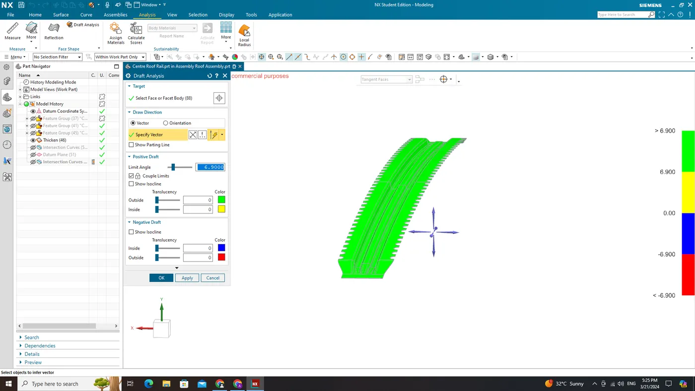
The Draft Analysis command enables you to detect if the part you drafted will be easily removed. This type of analysis is performed based on color ranges identifying zones on the analyzed element where the deviation from the draft direction at any point, corresponds to specified values.
Minimum draft angle of 7 is considered for analysis . green colour infer on the parts that all face along the tooling direction has positive draft angle greater than 7 and passed in analysis.
Conclusion:
- We learn how industries address challenges, how they approach new initiatives, and how they develop car BIW.
- We learn about roof design parameters such as visibility (front and back), headroom clearance, bow roof placements, and so on.
- We learn about the curvature study, draft analysis, snow load criteria, heat distortion criteria, crash test information, bow positions, section modulus, solid moment of inertia, roof manufacturability, and roof manufacturing procedures.
- The roof design passes in heat distortion condition, snow load condition, the design is manufacturable, the roof strength is good.
- Throughout every stage of development – from initial concept creation through final report preparation – meticulous attention was paid to ensure accuracy in all aspects related to dimensions, tolerances, material selection considerations, manufacturing feasibility assessments.
Note:
As the file size is greater than 20MB, I have uploaded in my google drive and here is the link for it.
https://drive.google.com/file/d/1rh9WZ15D-cQ_8DysiuRDOpU5P9fJuhF9/view?usp=sharing