Week 12- Final project
Development of a Door Trim Panel
Creation of CAD model considering following inputs as like in OEM and Tier-1 companies.
<!-- [if !supportLists]-->1. <!--[endif]-->a) Class A surface
<!-- [if !supportLists]-->2. <!--[endif]-->b) Nominal thickness: Refer master sections
<!-- [if !supportLists]-->3. <!--[endif]-->c) Attachment strategy:
Find an attachment strategy for the door panel complete work.
Use Push pin with Doghouse for Lower substrate – Door panel attachment.
Use heat stakes for part-to-part attachment.
AIM:
To develop a Door Trim Panel plastic component from a class "A" surface, by using the closed surface feature to create a solid part from the surface and to create "B" surface attachment features with the master section by considering the nominal thickness of a component.
OBJECTIVE:
- To create a Plastic Component of Door Trim Panel using the Class 'A' Surface.
- To create a Tooling Axis for a Class 'A' Surface, which meeting the requirement of the draft angle and to analyse the solid model.
- To create a Solid Model from the surface using the Closed Surface Feature.
- To create Attachment Features with reference to the created Class 'B' Surface.
- To follow the Master Section for Nominal Thickness and to follow the design rules.
- To create a Report which explains the Draft Analysis and Tooling Axis Creation - colour scale variant.
- To attach the screenshots of the Expanded Tree Structure for the Geometrical Sets.
- To attach the screenshots of the 3D Part Model in different orientations.
PART PUBLICATION:
- Class 'A' Surface.
- Tooling Axis.
- Side Core Tooling Axis.
- Class 'B' Surface.
- Class 'C' Surface.
- Solid Part.
INTRODUCTION:
TOOLING DIRECTION:
The tooling direction is the direction that the mold pulls apart. The mold is built in two separate pieces,
- A cavity side.
- A core side.
The core pulls apart from the cavity and that's the Dyeline or the Tooling Direction. The direction in which the mold or core and cavity opens is the tooling axis.
FEATURES OF TOOL:
- Cavity half – The cavity half is the side of a tool that does not move. It is typically attached to the side of the molding machine.
- Core half – The side of the tool that opens and closes with the mold machine against the cavity half. It opens when removing the part from the tool.
- Cooling Lines – Channels that allow coolant to flow throughout the tool and control the cooling of the plastic part.
- Ejector System – Pins on the core half of the tool that helps push the cooled part out after molding.
- Runner – A flow path for the plastic resin allowing the press to inject material directly into the part cavity.
- Side Core – Moving pieces within the part cavity added to allow for undercuts.
ASSEMBLY WORKBENCH:
The assembly workbenches use constraints and expressions to create relationships between the objects in model, to mathematically tie the objects in place.
The components are brought together and assembled in Assembly Design workbench by applying suitable parametric assembly constraints to them. The assembly constraints allow you to restrict the degrees of freedom of components on their respective work positions. The assembly files in CATIA are called Product Files.
TOP - DOWN ASSEMBLY APPROACH:
Top-down assembly approach is a method of creating and designing the geometry within an assembly. This is also called “in-context design” because everything is created in the context of an assembly.
BOTTOM - UP ASSEMBLY APPROACH:
Bottom-up assembly approach is a method of creating and designing every individual part separately. In the bottom-up approach, all the parts need to be created correctly with all the right dimensions to ensure they fit properly.
DOOR ARM REST
CLASS A SURFACES:
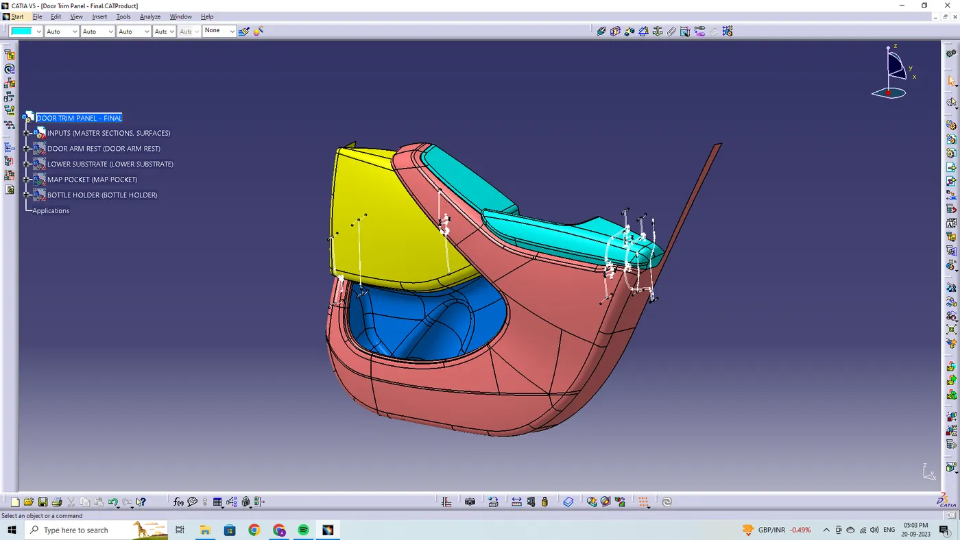
By using the Top -Down Approach, the step files are being converted into CAT part files using assembly workbench. The four different types of class A surfaces are being imported into assembly workbench and combined to form a CAT Product with master section.
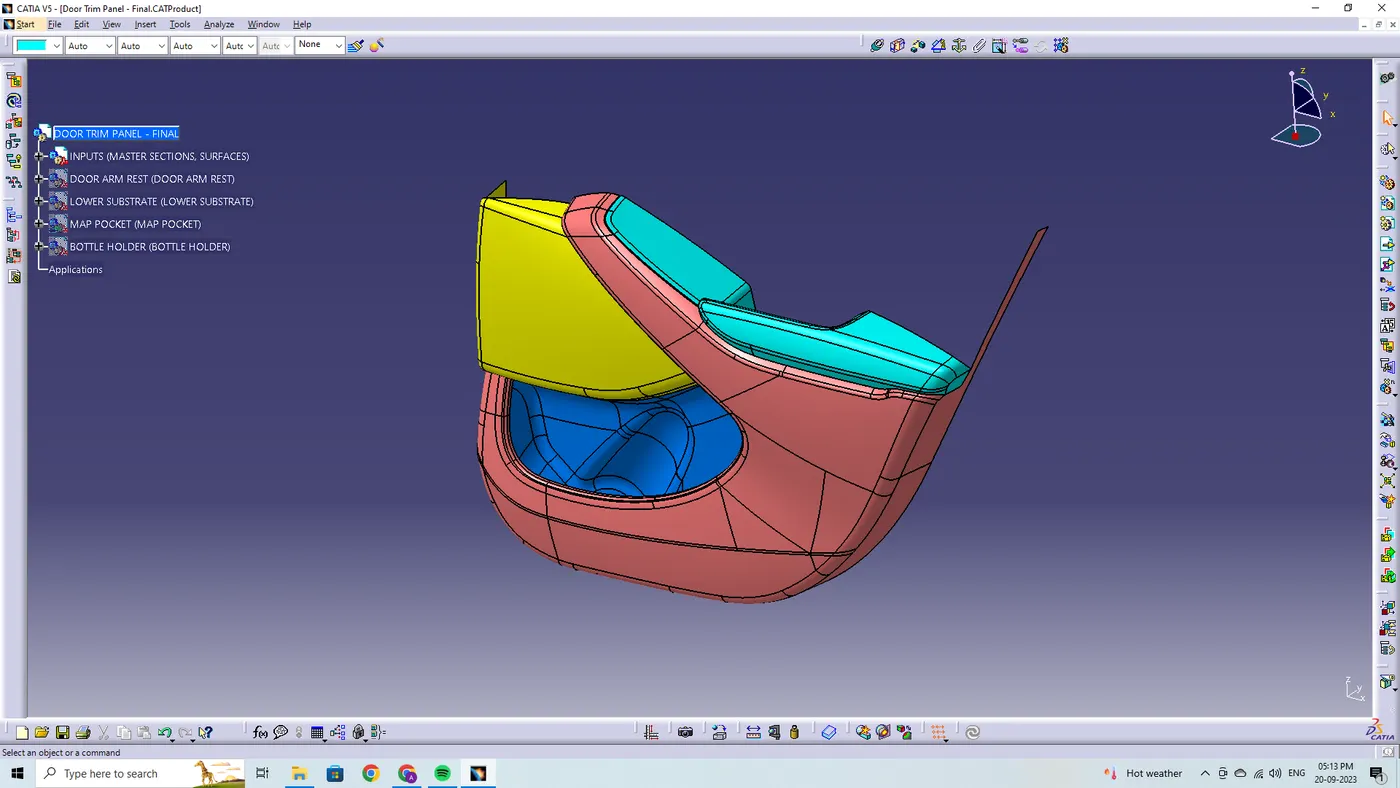
WITH MASTER SECTIONS:
DESIGN CHECK:
The class A surface is checked visually by using the join feature or by using the boundary feature the class A surface is selected and disassembled the surface to check the surface are created without the gaps. The class A surface should be created without boundary gaps. By using the join definition with the merging distance of 0.001 mm the class A surface is joined together to check the connectivity.
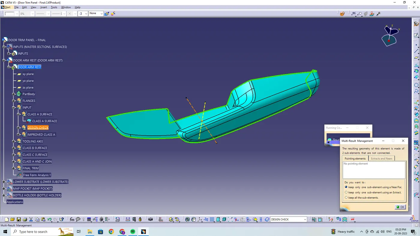
IMPROVED CLASS- A SURFACE:
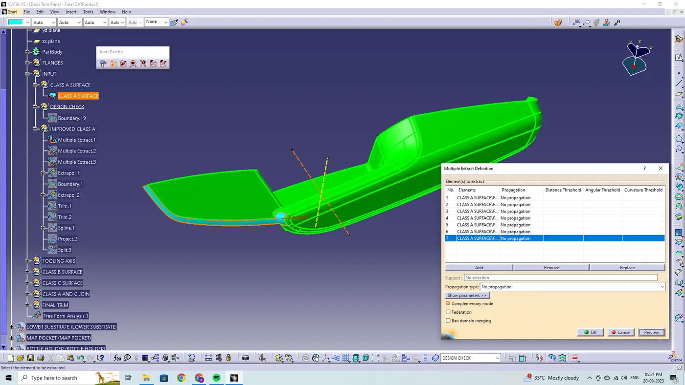
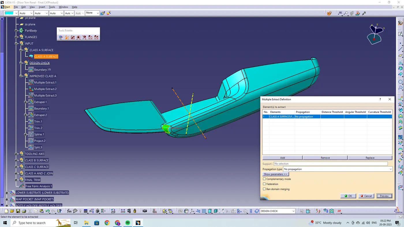
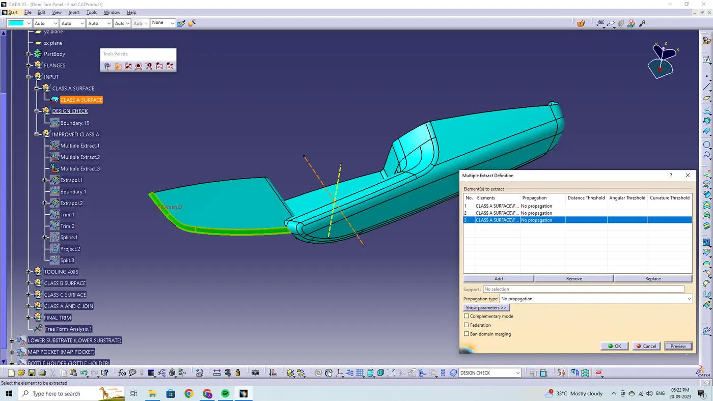
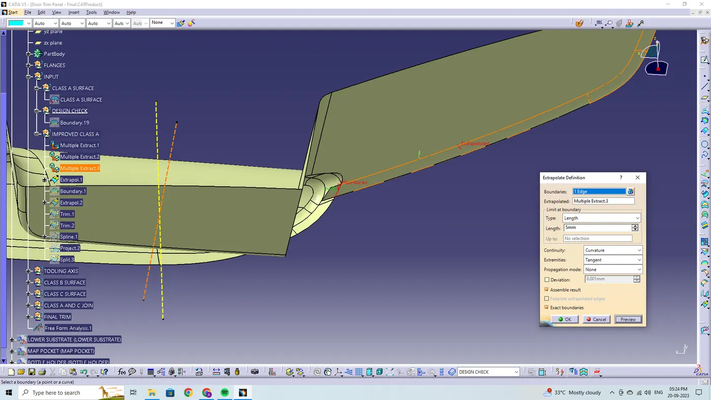
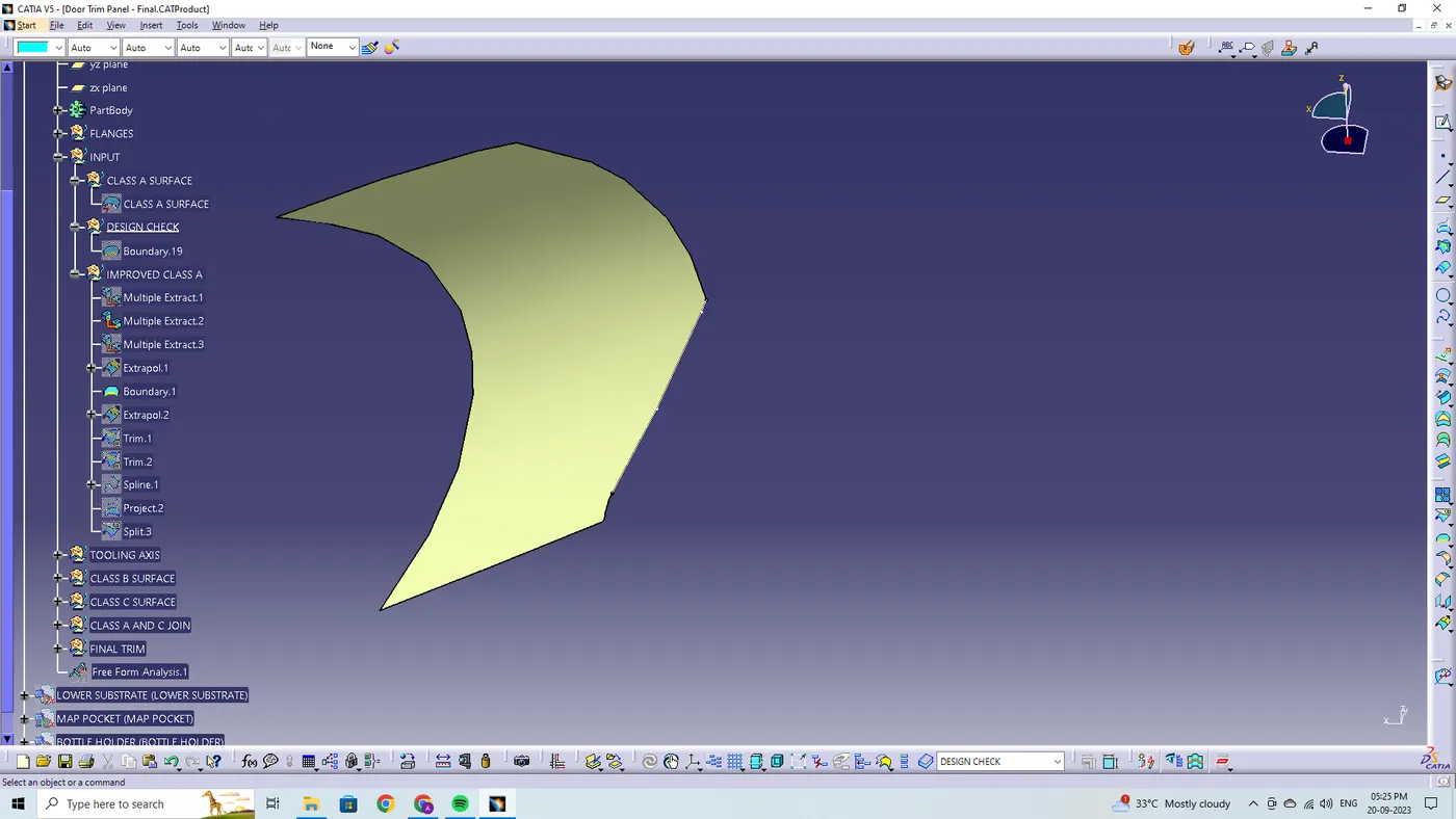
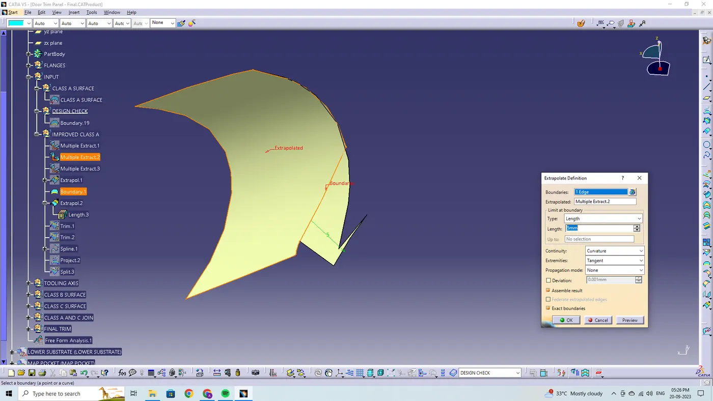
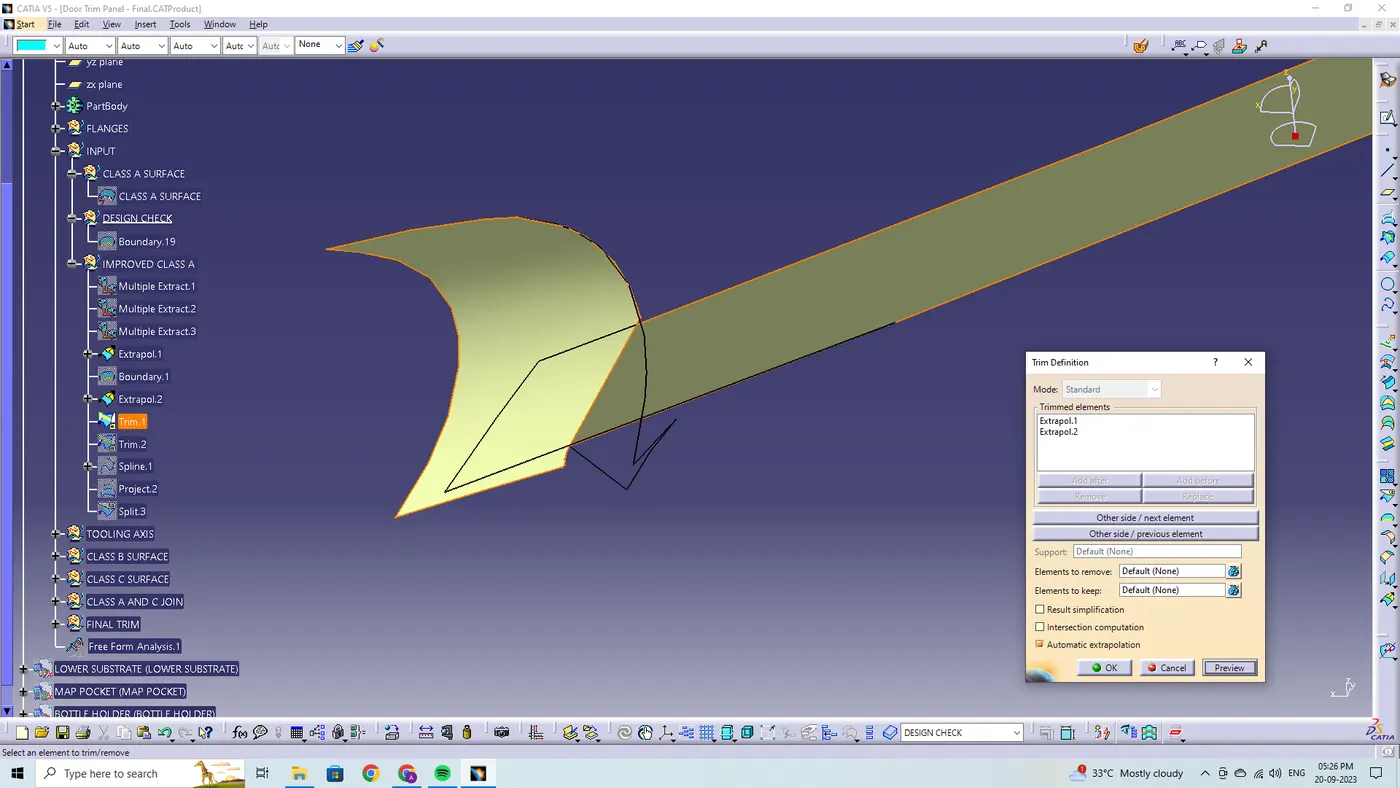
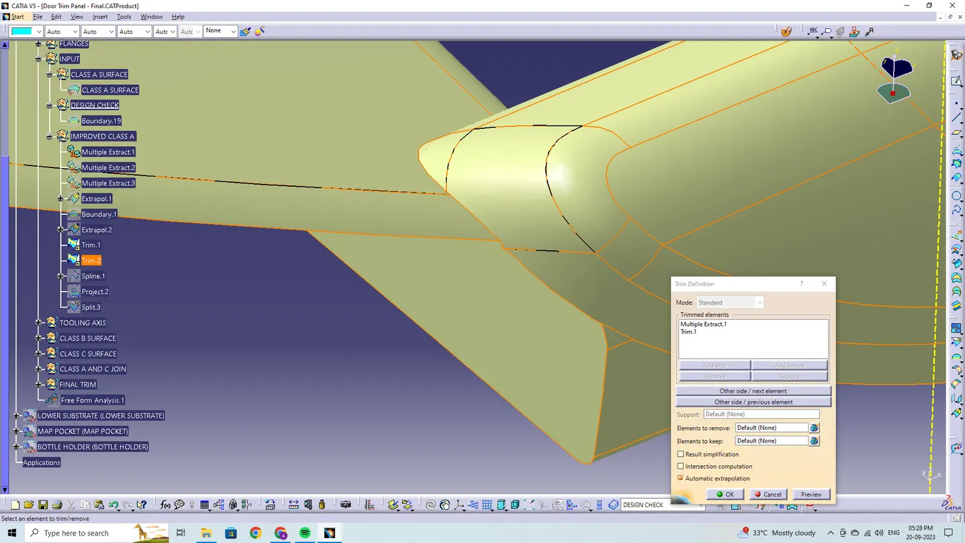
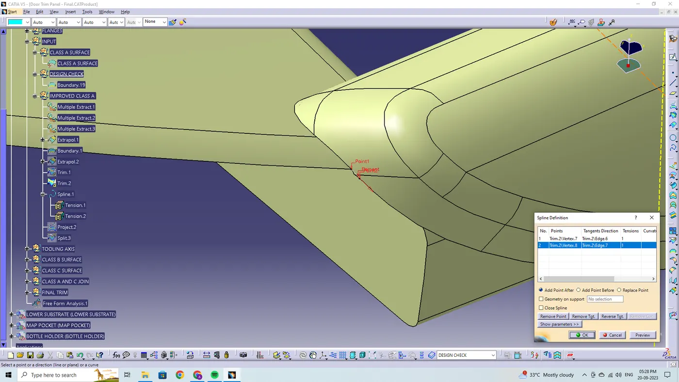
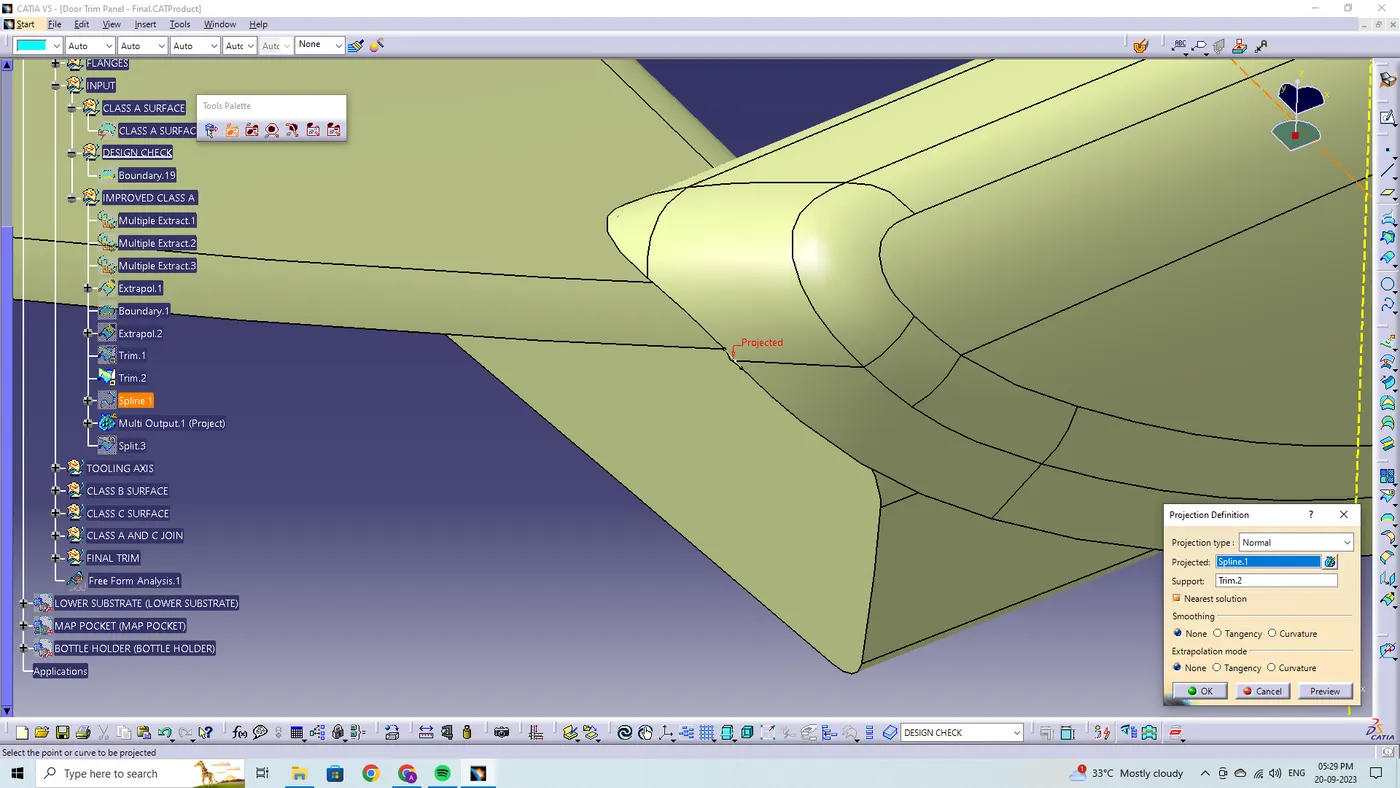
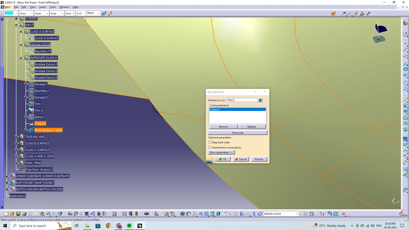
The class A surface is getting improved because of 2 sub-elements on the surface which was noticed in the design check phase.
CREATING TOOLING AXIS:
The tooling for the class A surface is created in the direction in which the parts are ejected from the tool. The tooling axis which defines the core and cavity pulls apart from the tooling direction.
By using the extract feature definition, along the x,y,z co-ordinate system the surfaces (Surfaces are likely to see visually) are selected and extracted.
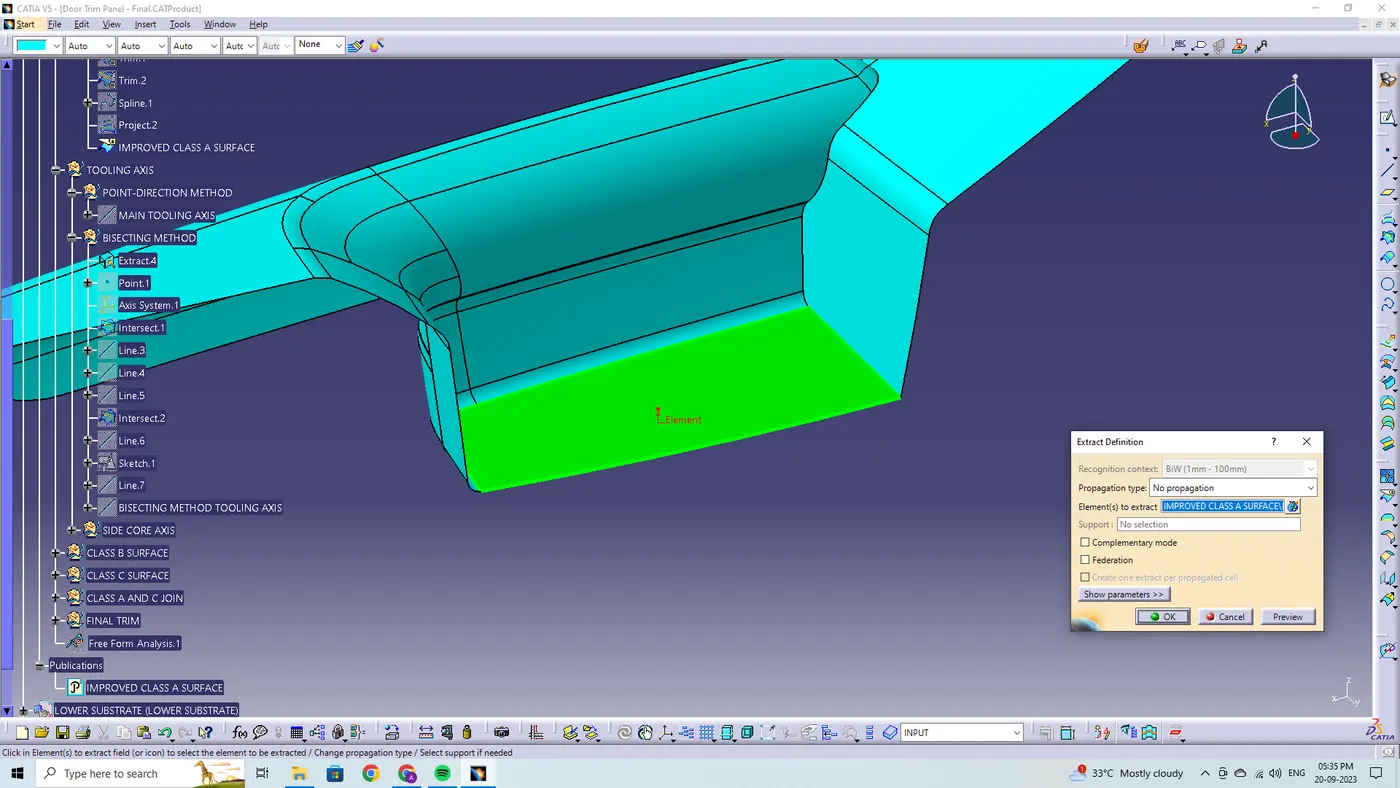
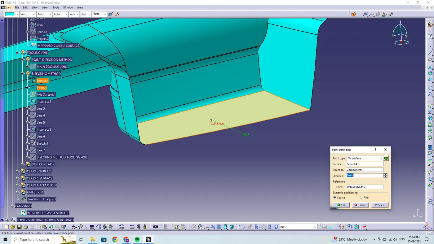
By using the point definition, the point has been created on surface midpoint along Y- direction.
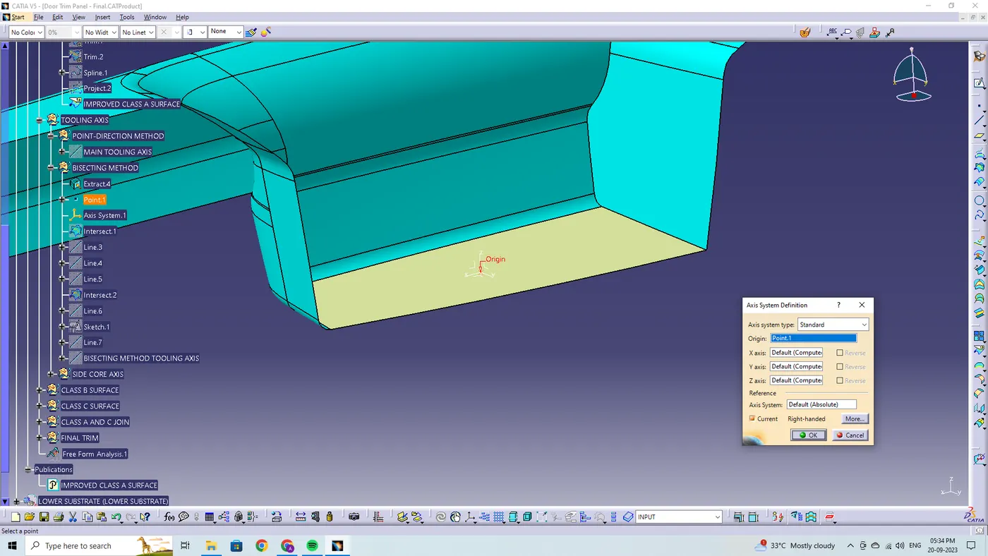
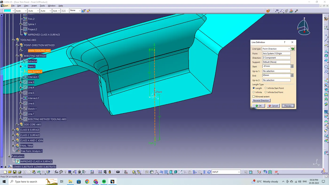
The main tooling axis has been created using the line definition feature. From the line type point direction, point has been selected and direction along Y component are selected to define the line.
SIDE CORE AXIS:
DRAFT ANAYSIS:
For a class A surface, the draft analysis is to be performed to meet the requirement of the draft angle to the required tooling axis. For plastic components the minimum angle required for the draft to be 3 degrees.
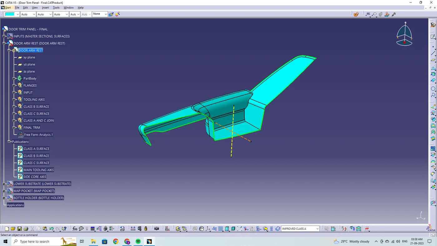
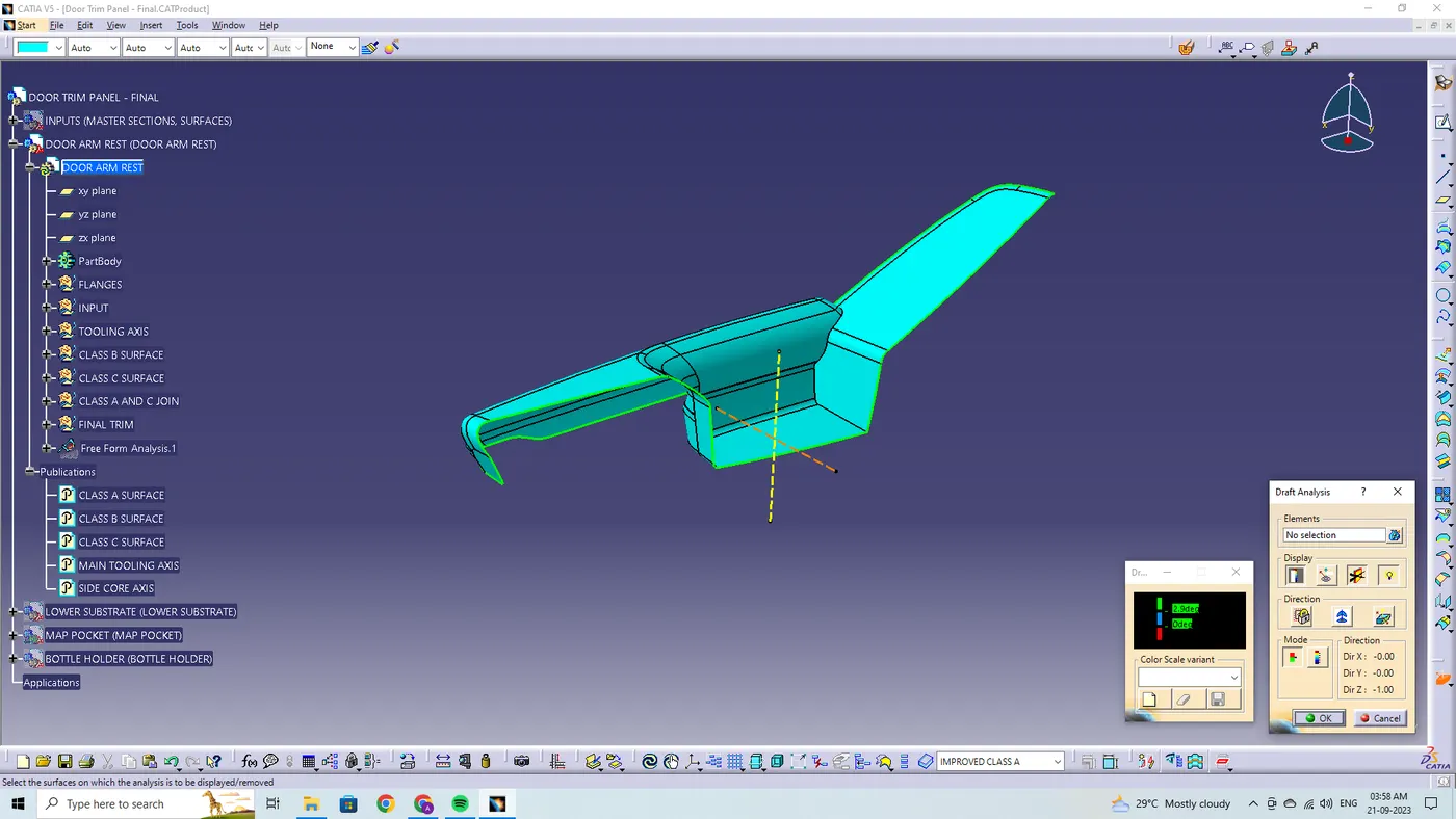
The direction compass is to be selected and placed on the main tooling axis line and the compass is being locked using the lock feature in the direction.
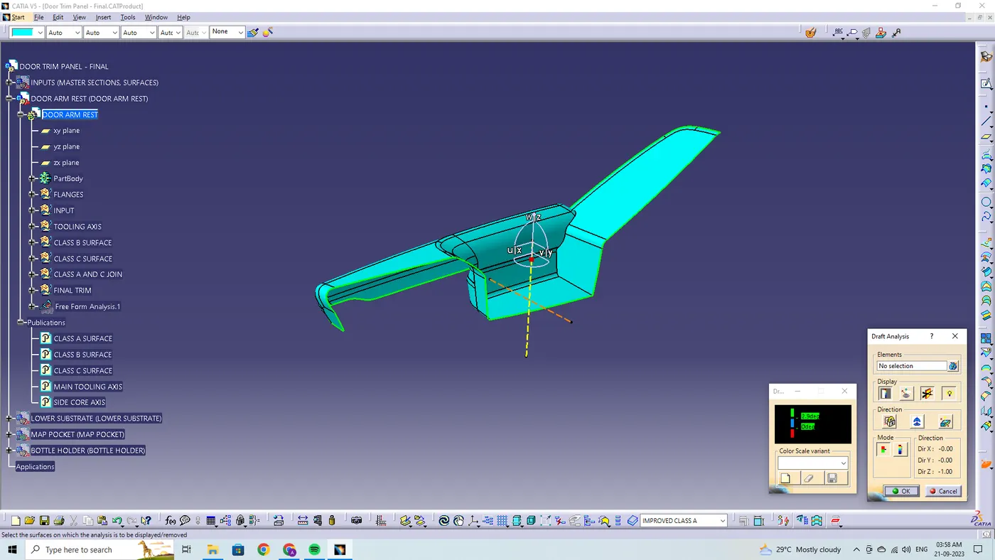
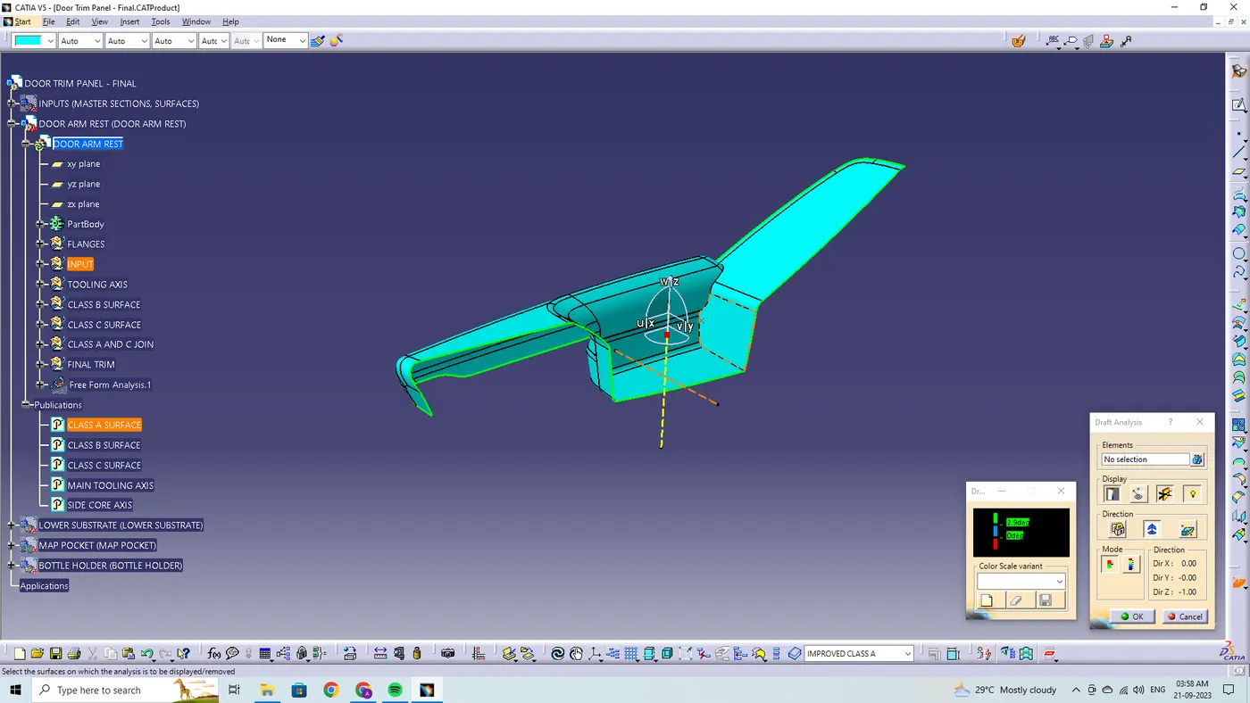
In the display window the color code variants are being selected, to know the range of the draft in the class A surface. In the display window the color variant shows,
- For 3 degree - Green color variant (Positive)
- For 0 degree - Blue color variant
- For <0>
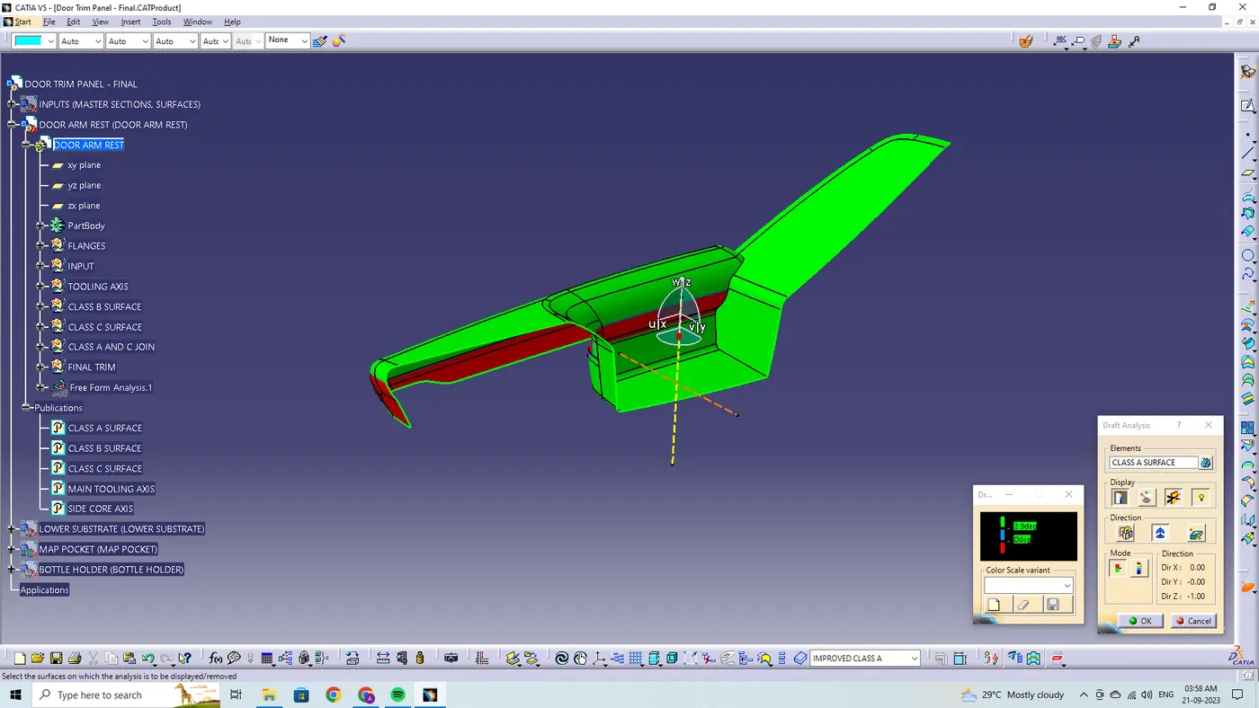
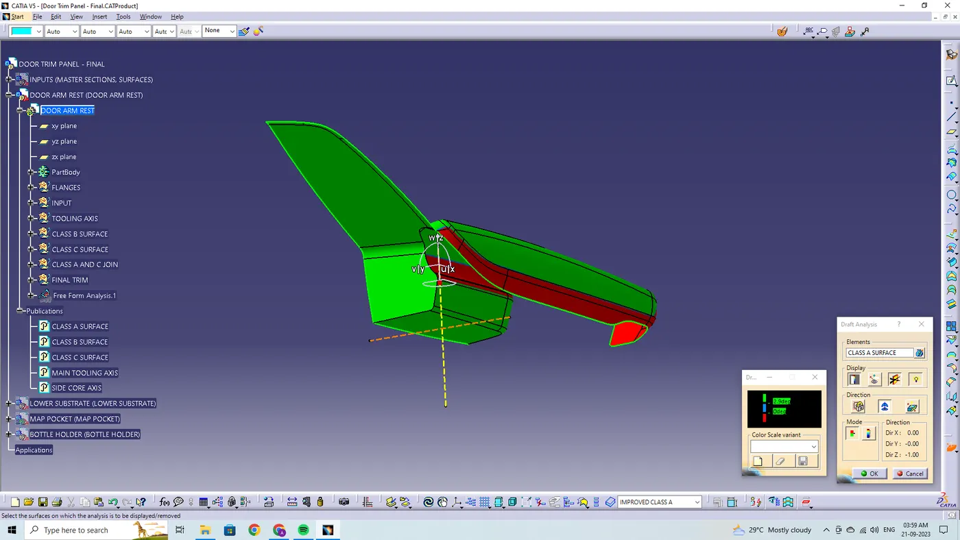
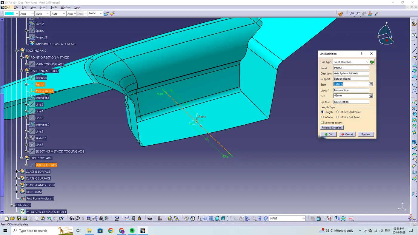
The side core tooling axis is created to clear the draft on the undercutted surfaces.
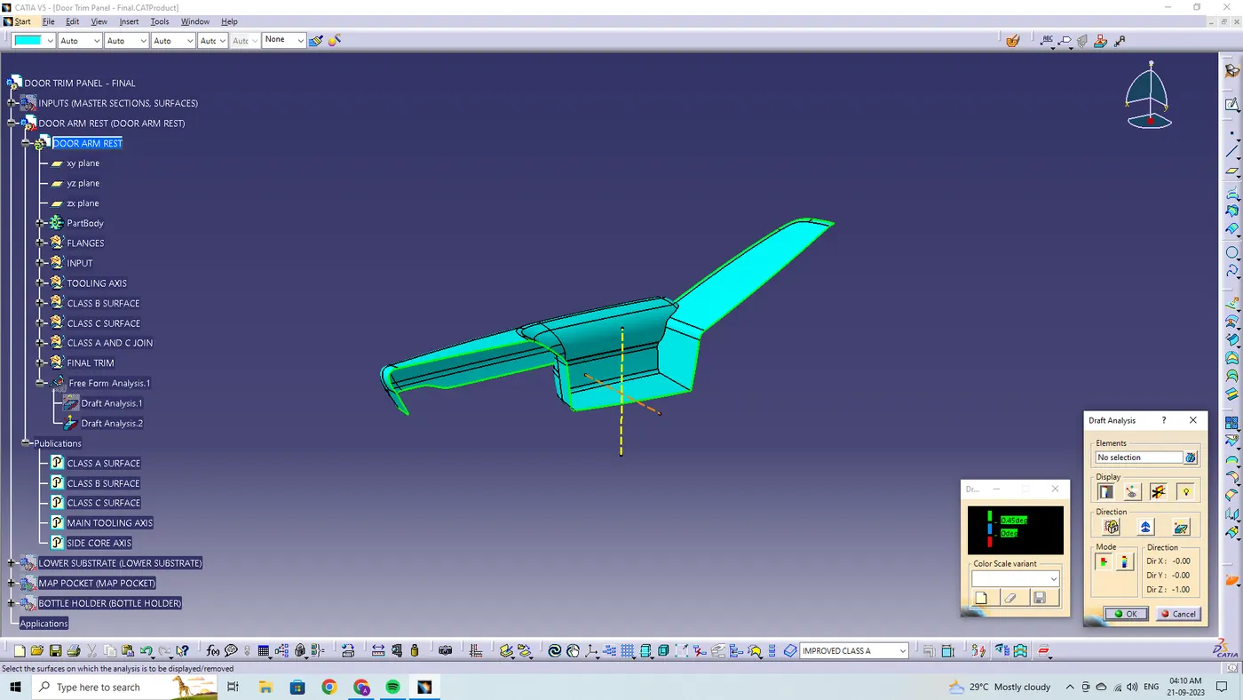
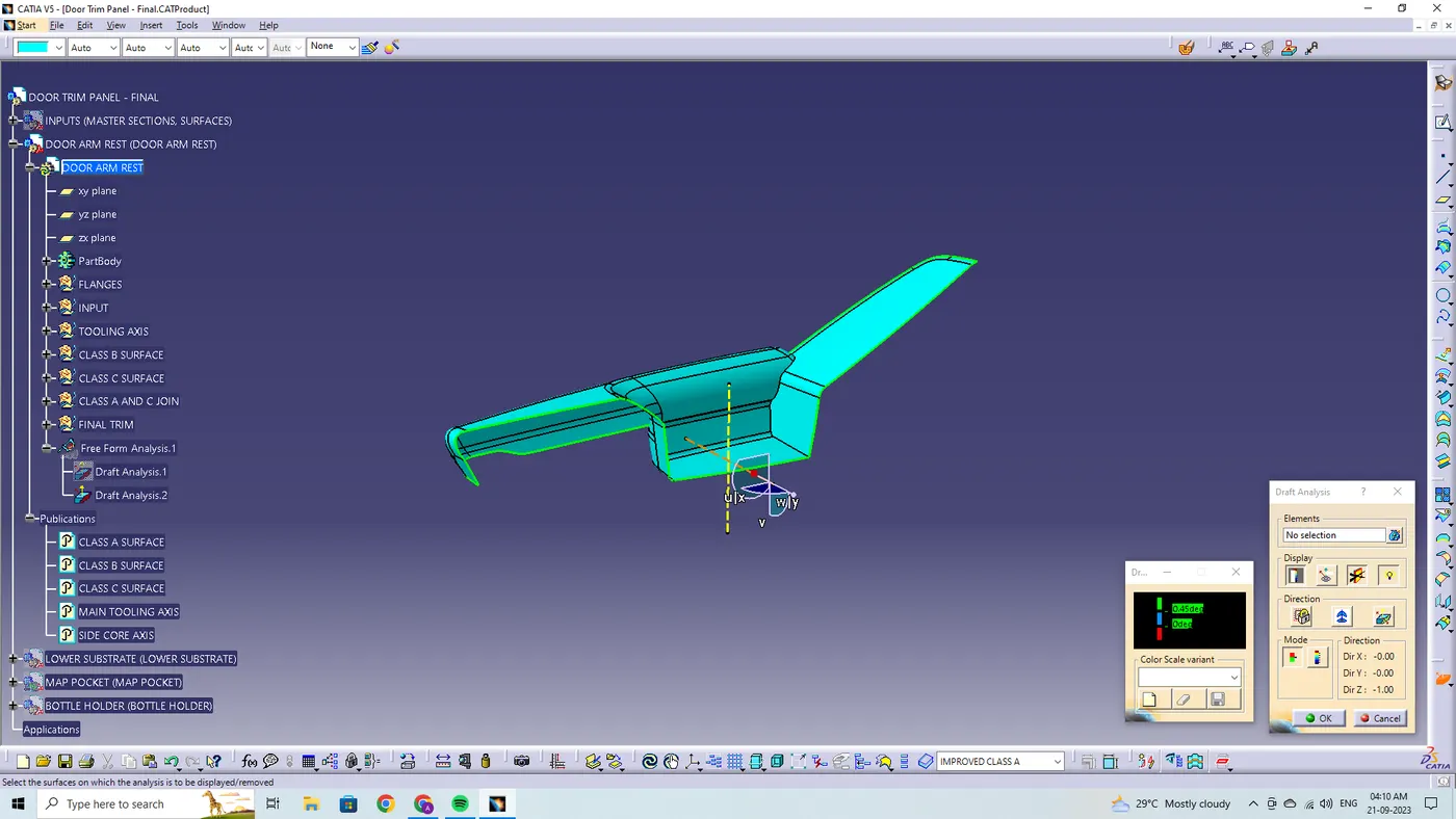
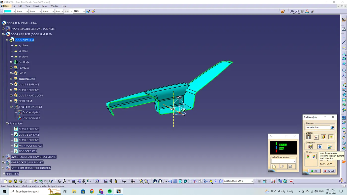
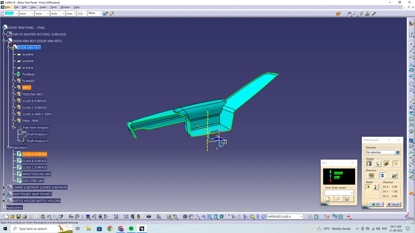
In the display window the colour code variants are being selected, to know the range of the draft in the class A surface. In the display window the colour variants show,
- For 3 degree - Green color variant (Positive)
- For 0 degree - Blue color variant
- For <0>
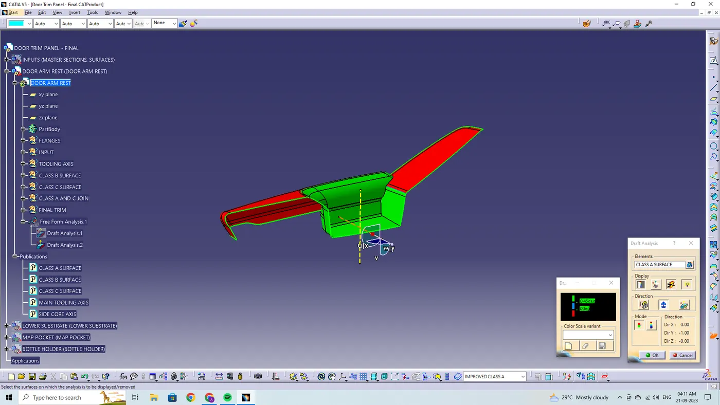
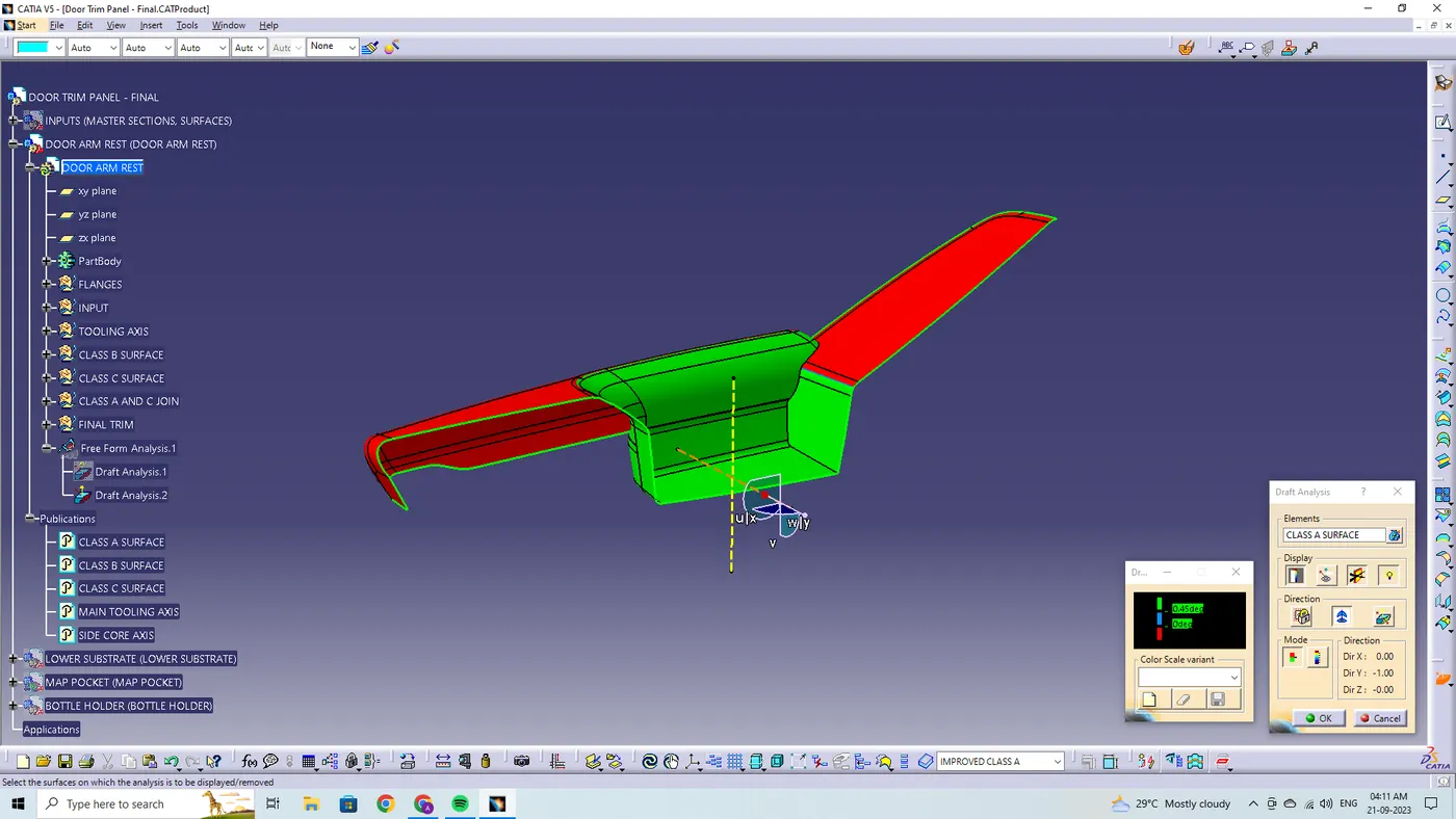
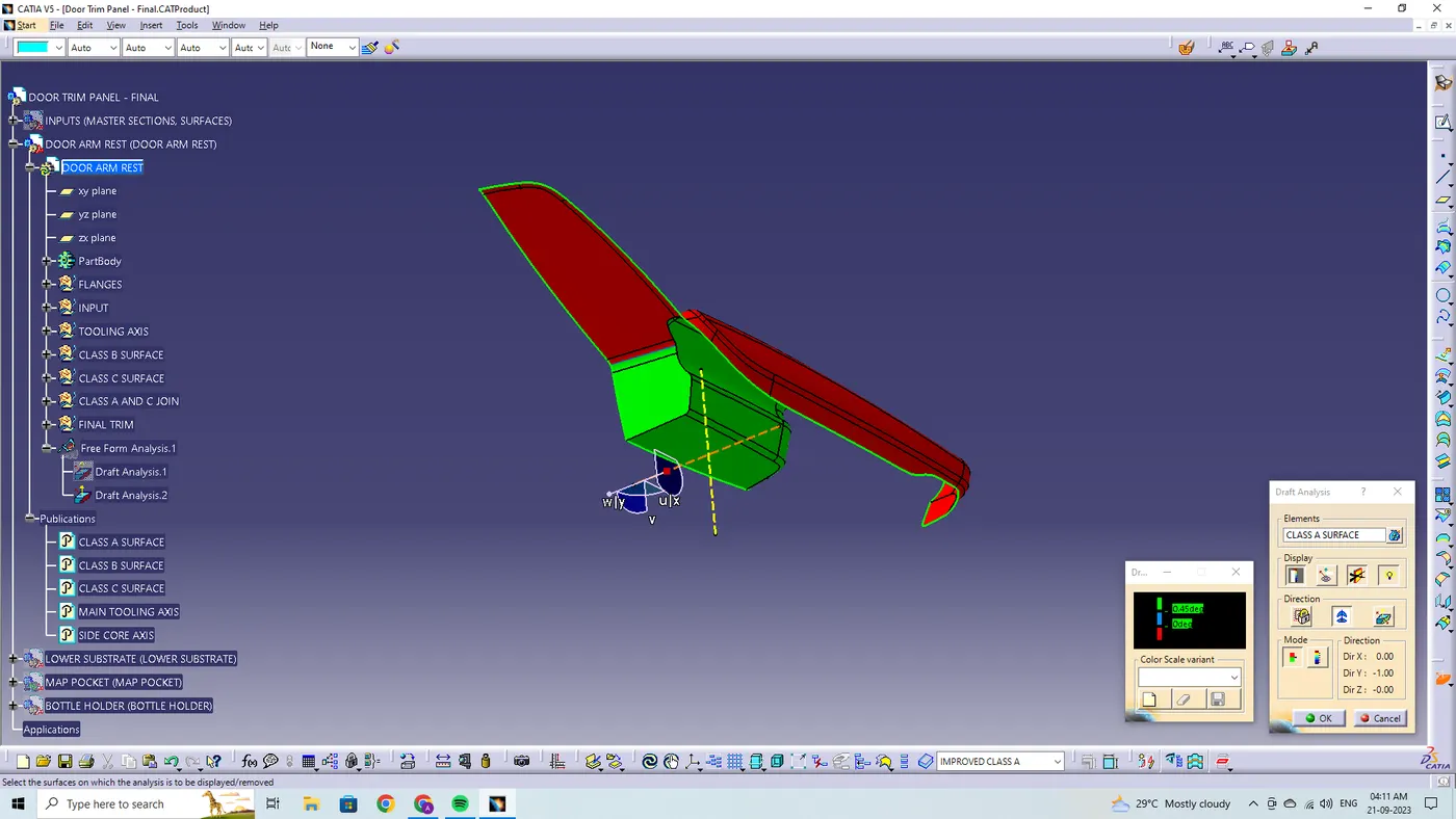
The draft analysis is being performed in both the core and cavity side of solid body. The green colour implies the draft angle are in the positive region. If the draft angle is being inverted the colour of the surface are implied as blue colour.
CREATION OF CLASS 'B' SURFACE:
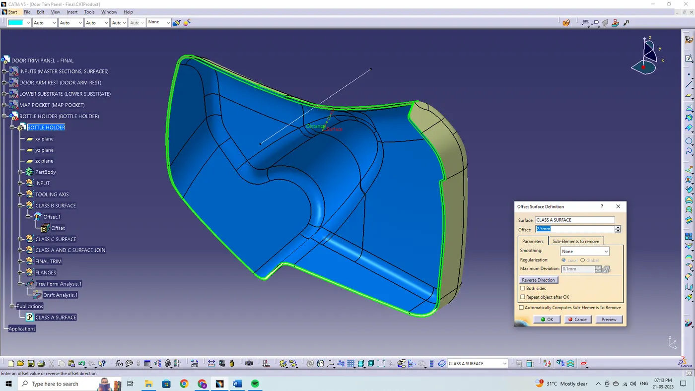
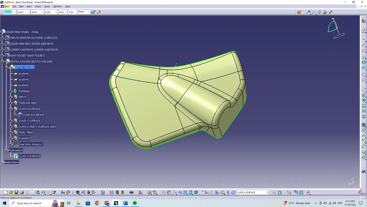
By using the class A surface, the class B surface is created by offsetting to the respective length to the respective direction. By using the offset surface definition the class A surface is being offset to the length of 2.5 mm to the respective direction.
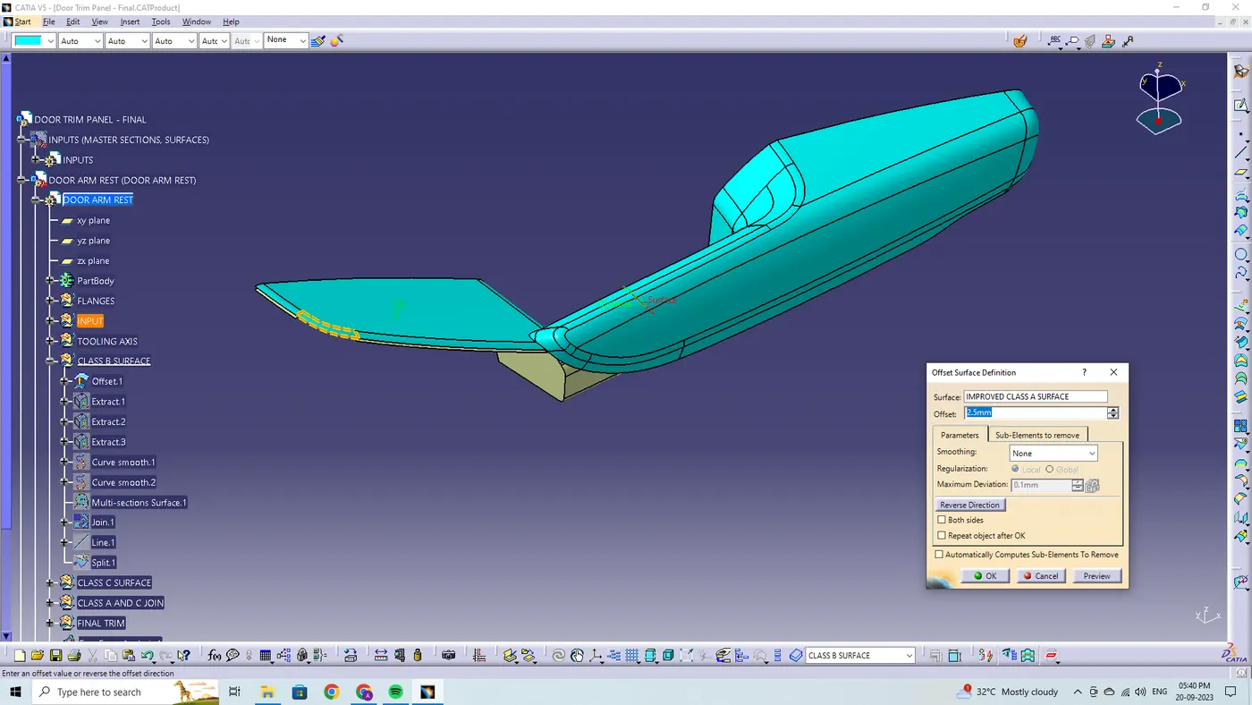
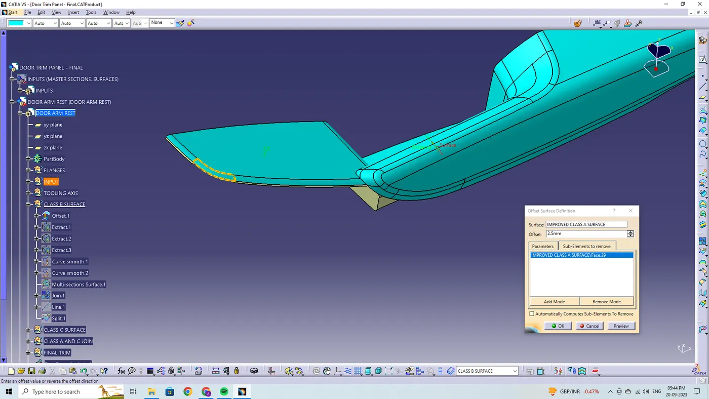
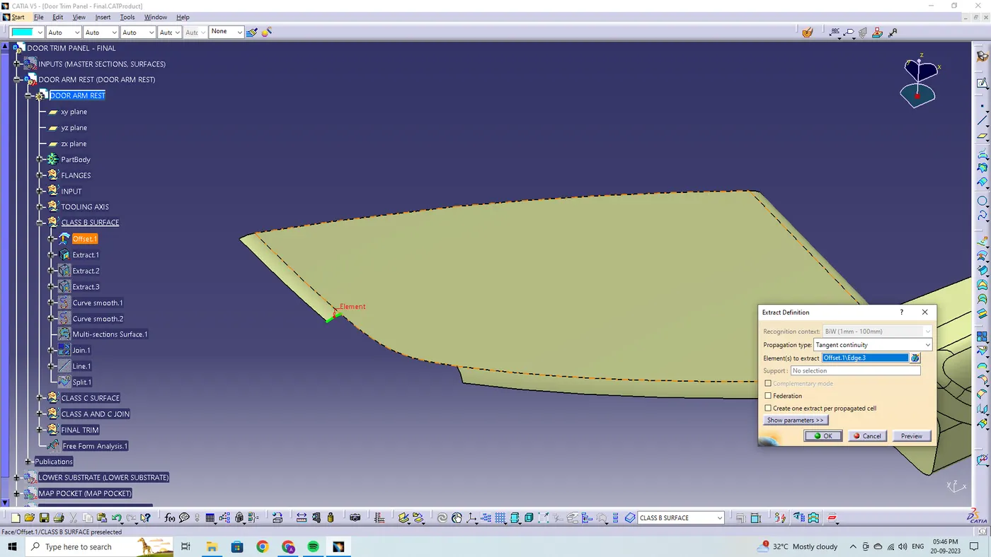
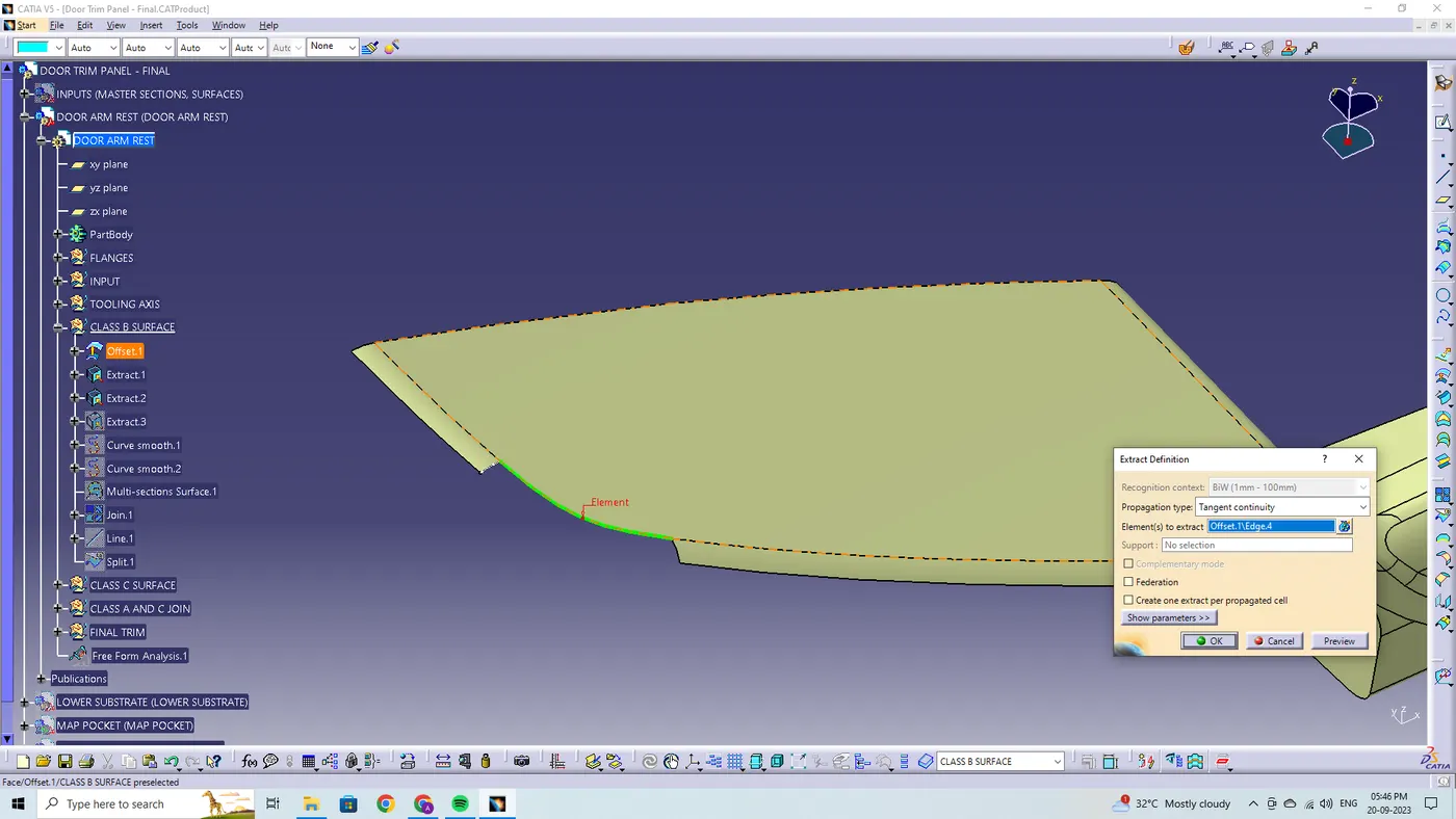
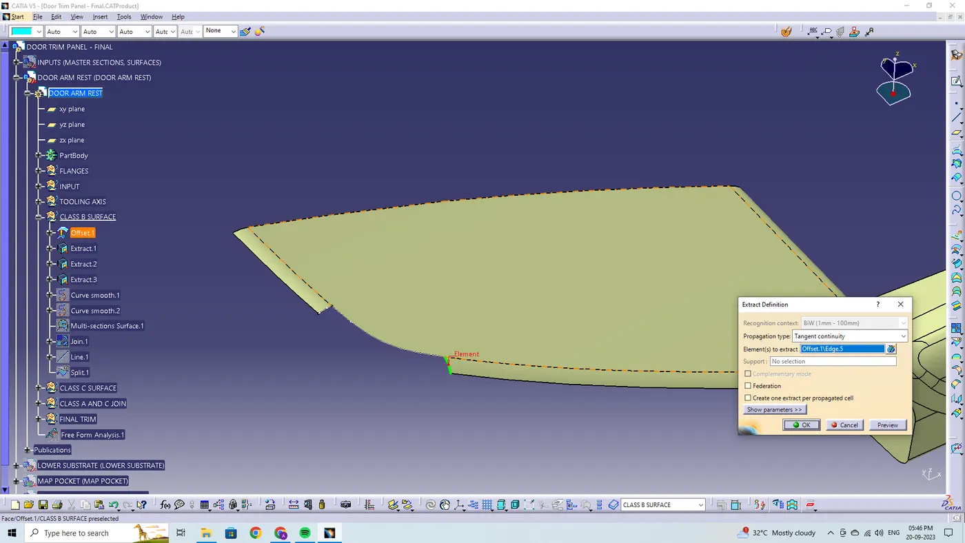
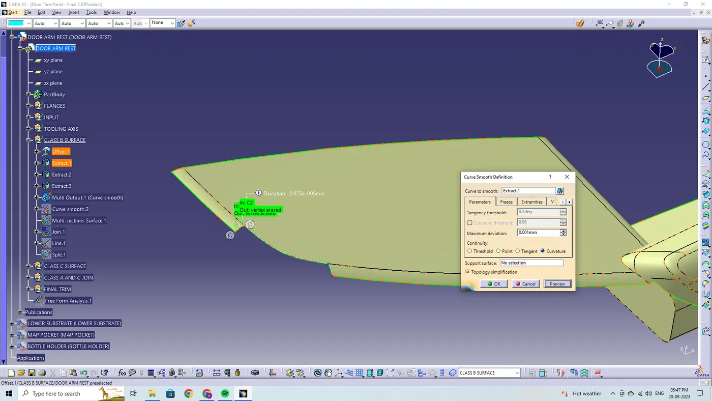
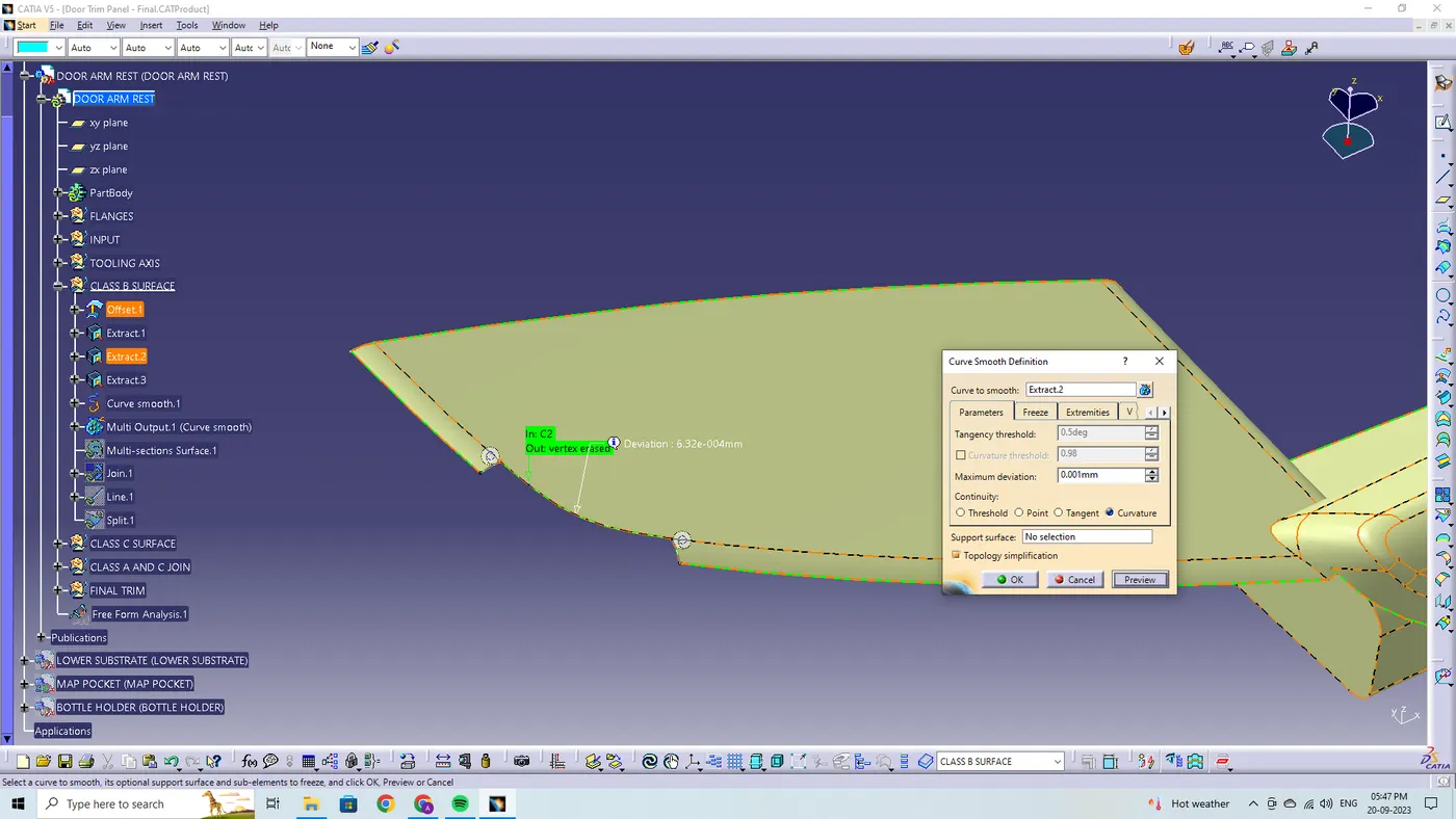
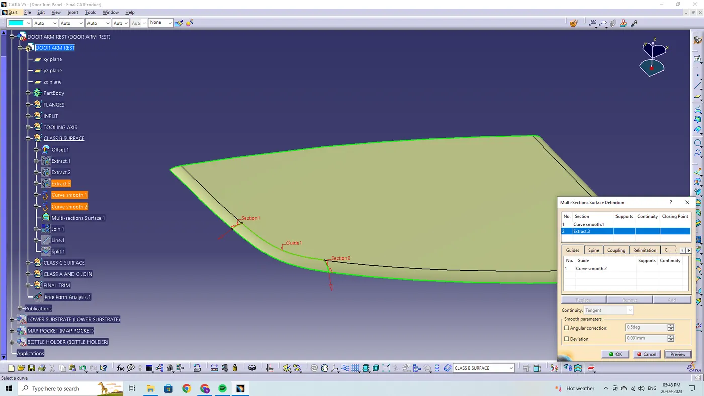
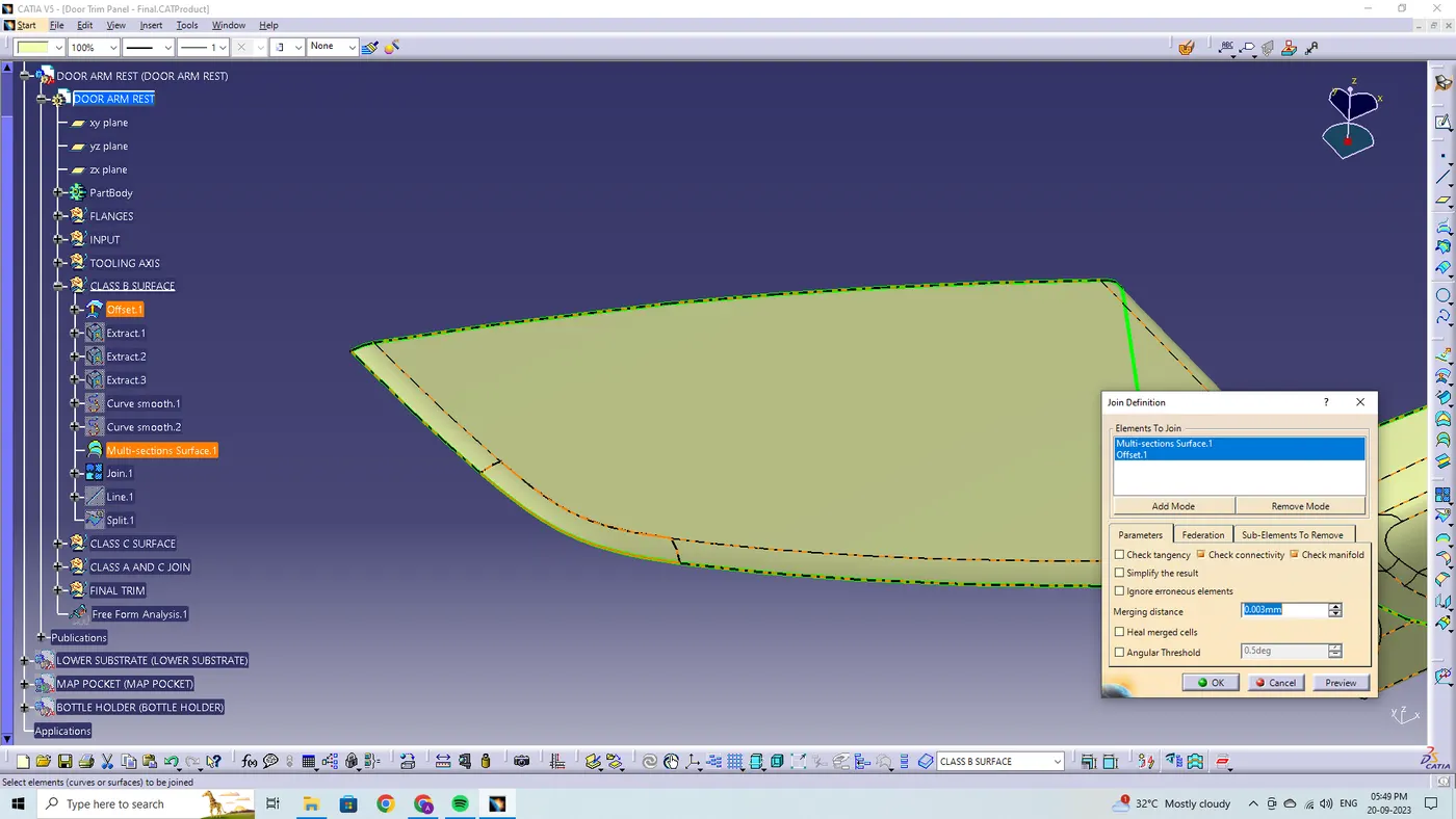
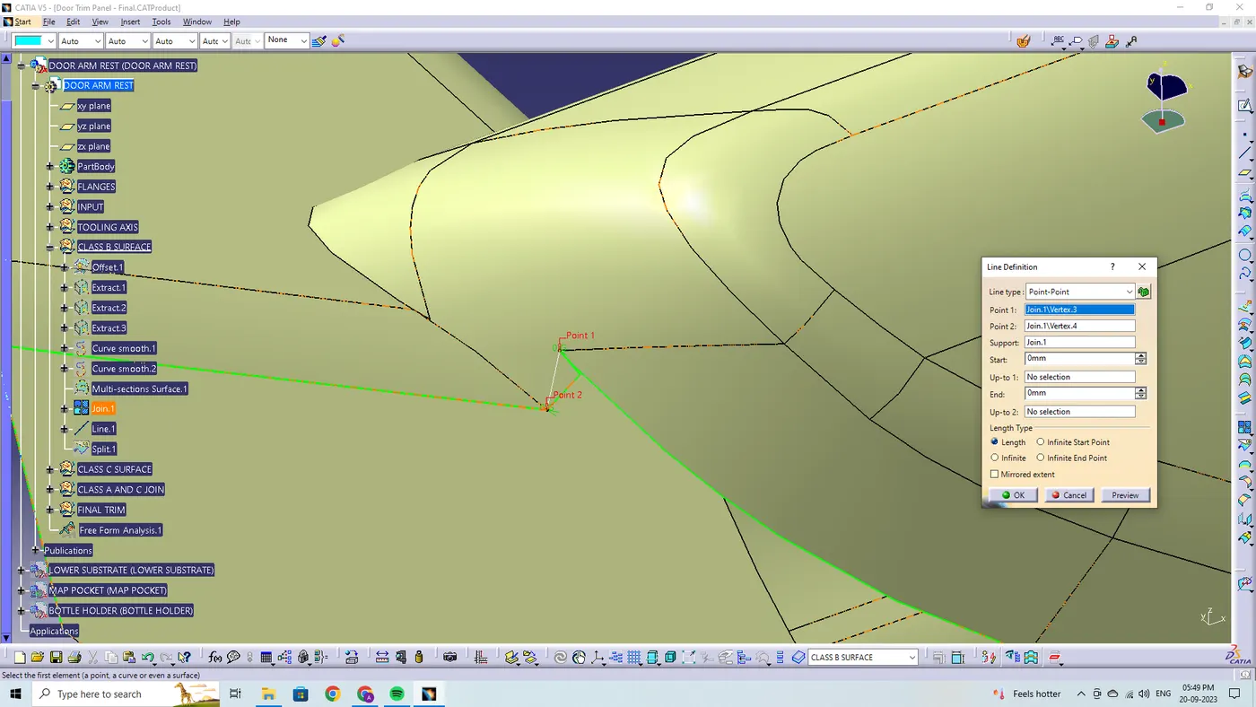
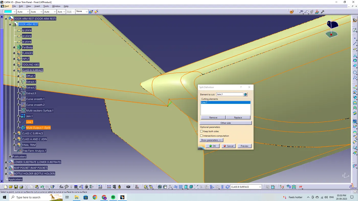
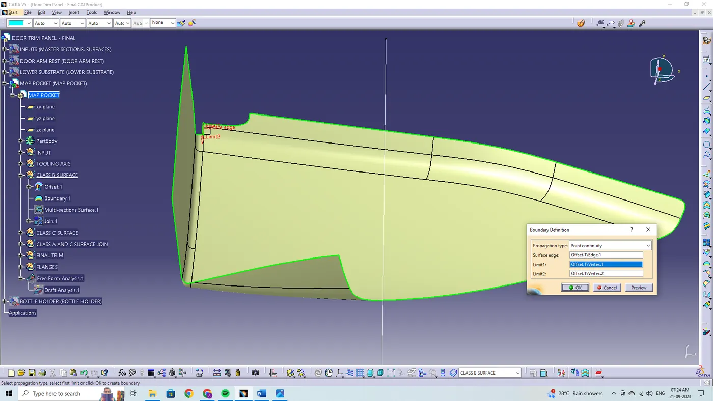
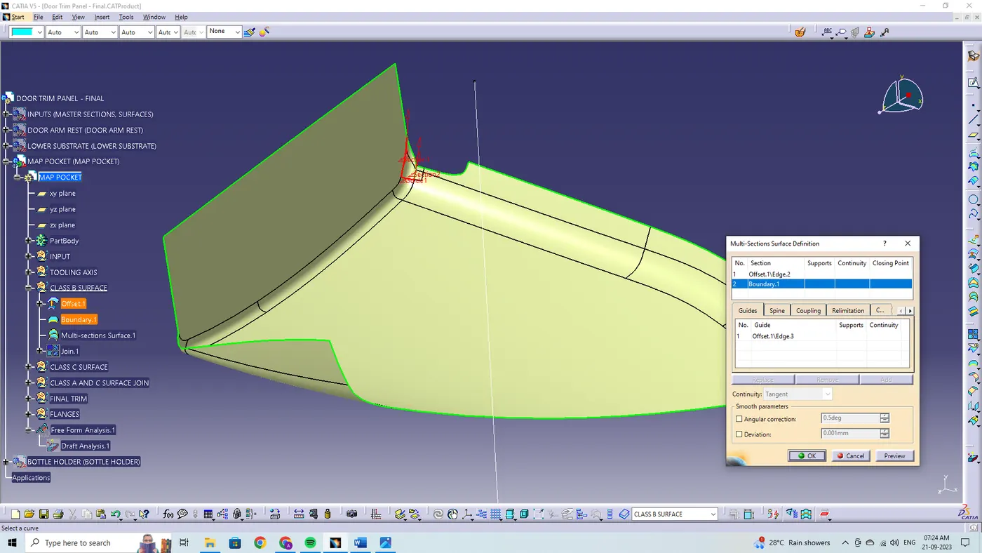
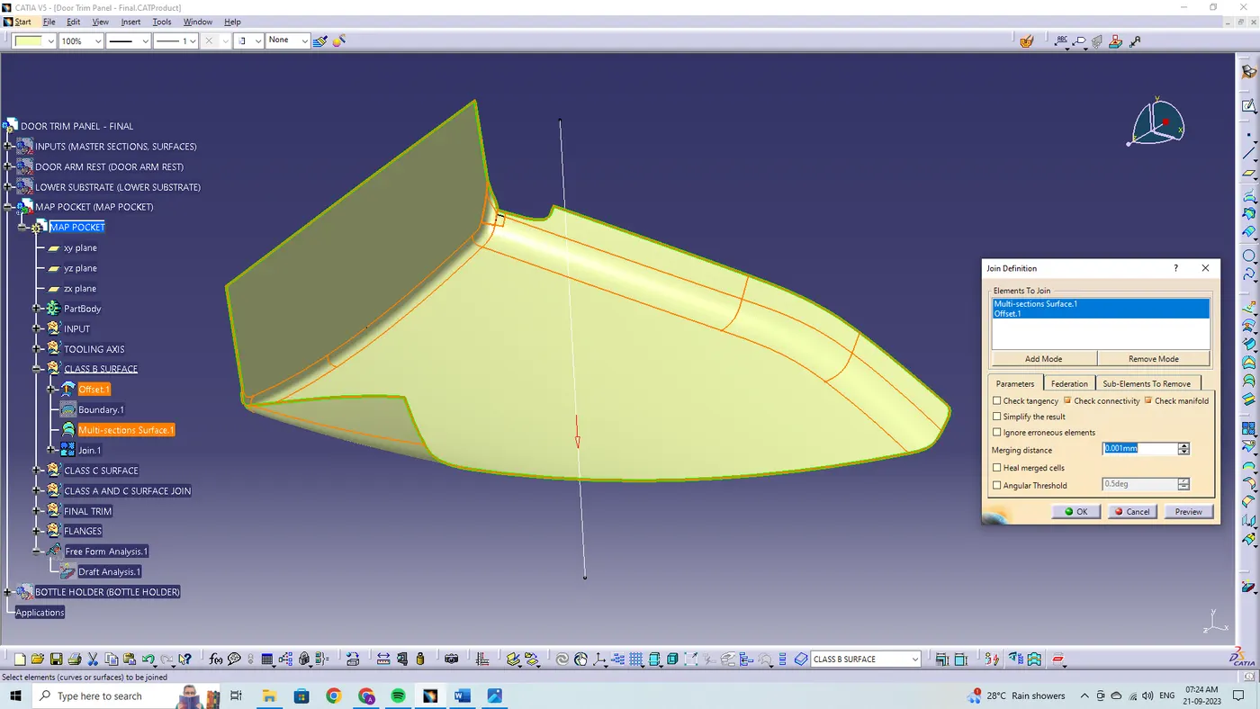
The class B surface is checked visually by using the join feature or by using the boundary feature. The class B surface is selected and disassembled the surface to check the surface is created without the gaps and to check the connectivity.
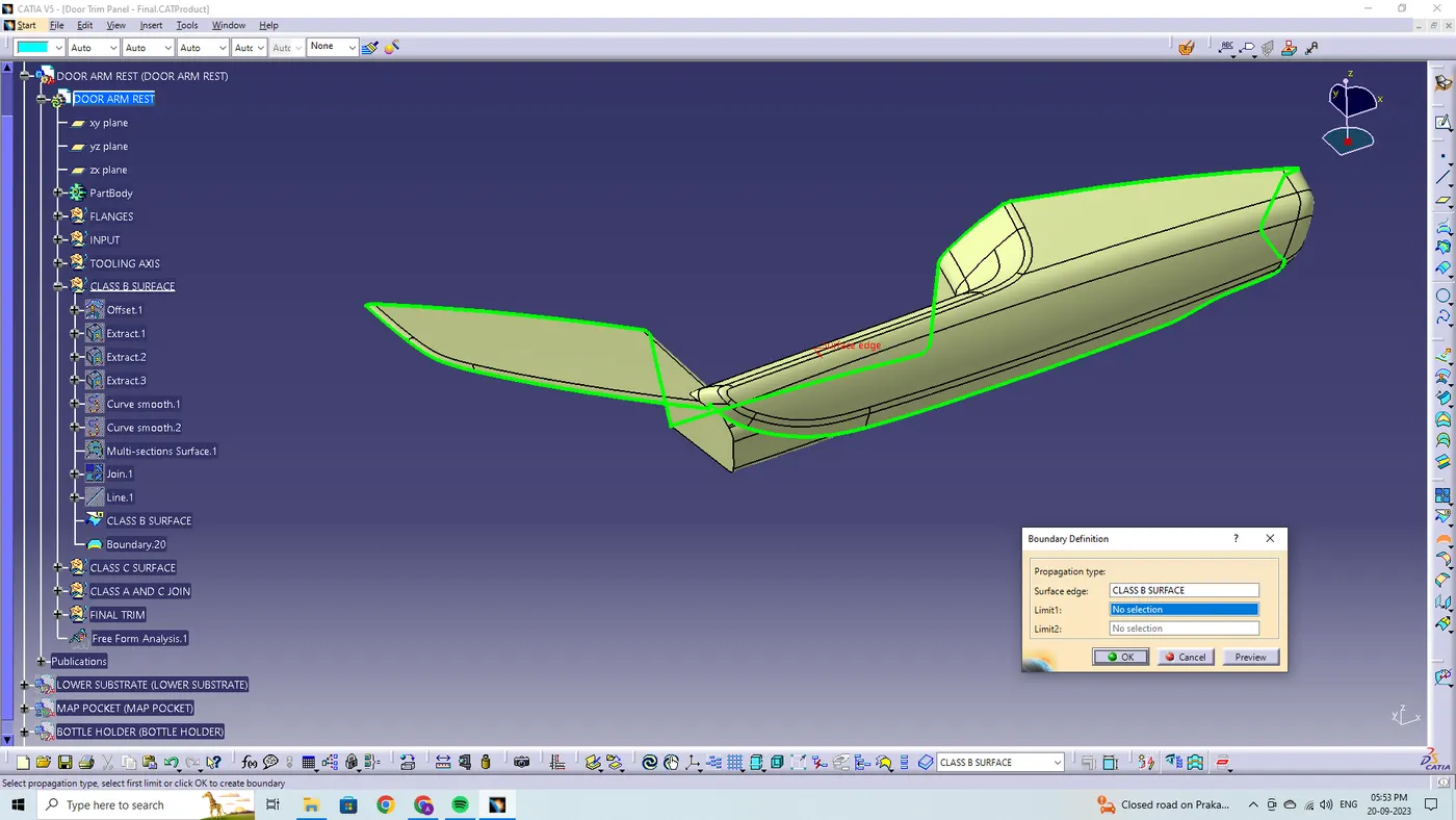
CREATING CLASS 'C' SURFACE:
To make the class C surface, the boundaries are extracted from the class A surface. The outer boundary is being extracted using the boundary feature/extract definitions.
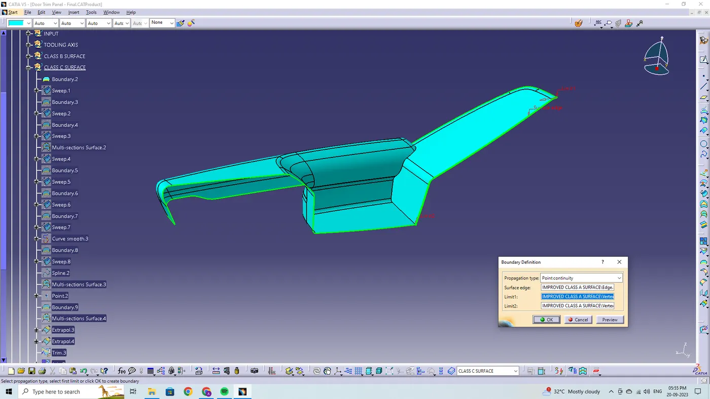
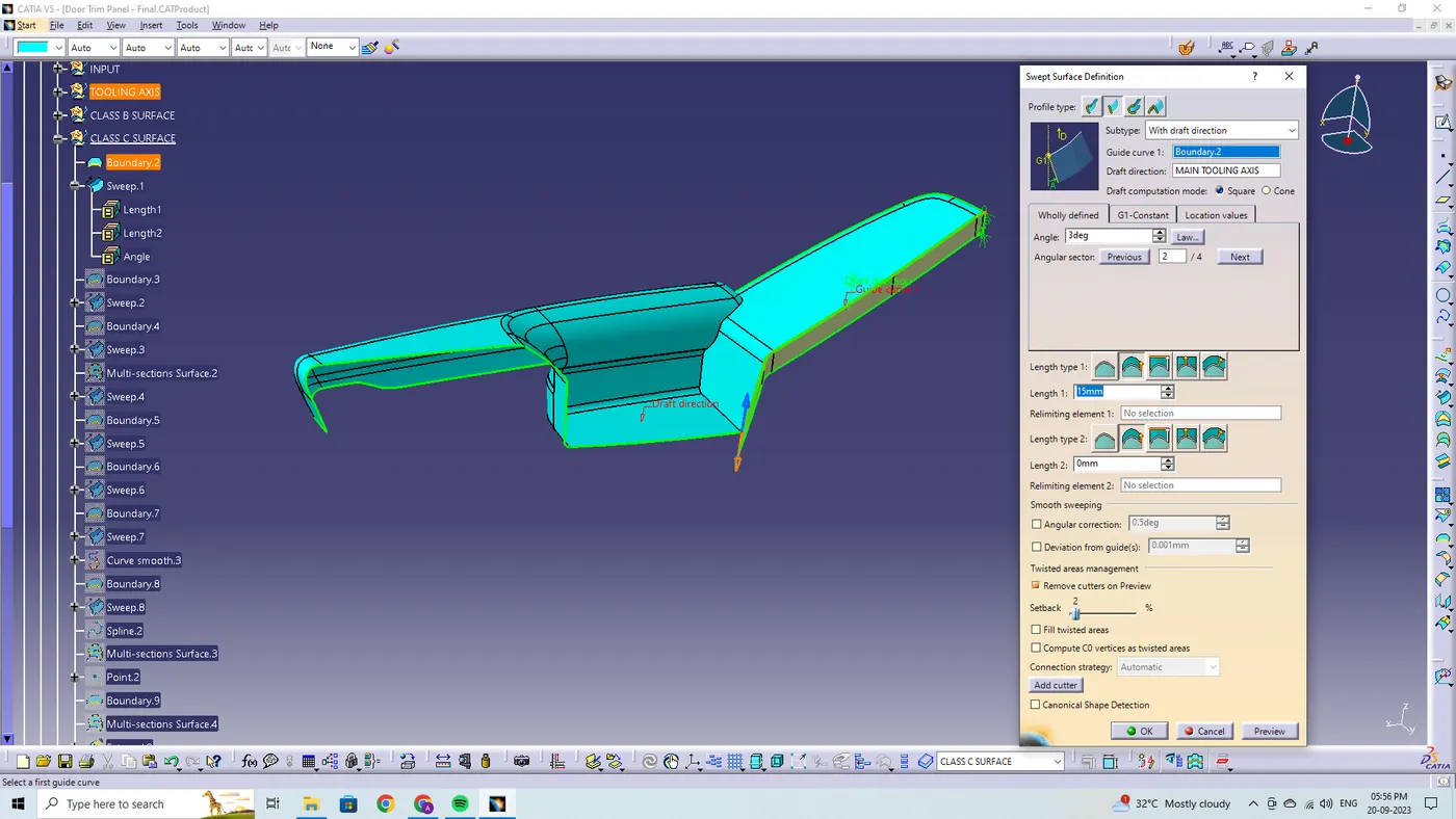
By using the sweep surface creation definition, the respective profile types are being selected and subtype with reference surface are being selected. In that the guide curve is selected as the boundary in the class A surface, and reference surface are selected, and the class C surface are being created to the respective length.
By using the join definition feature the created class C surfaces are being joined together, and by using the extrapolation and trimming feature the edges are being extrapolated and trimmed together to form the class C surfaces.
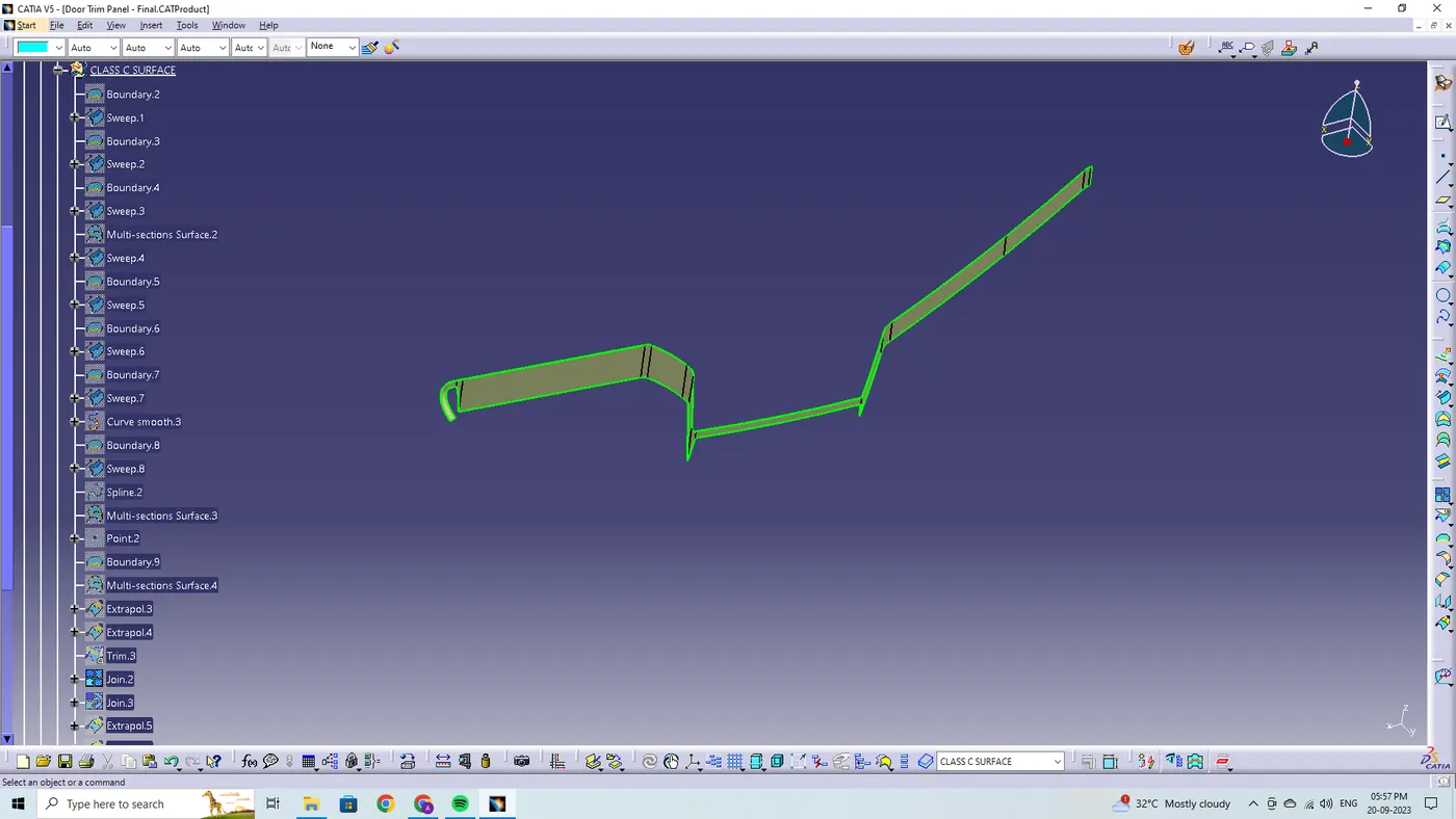
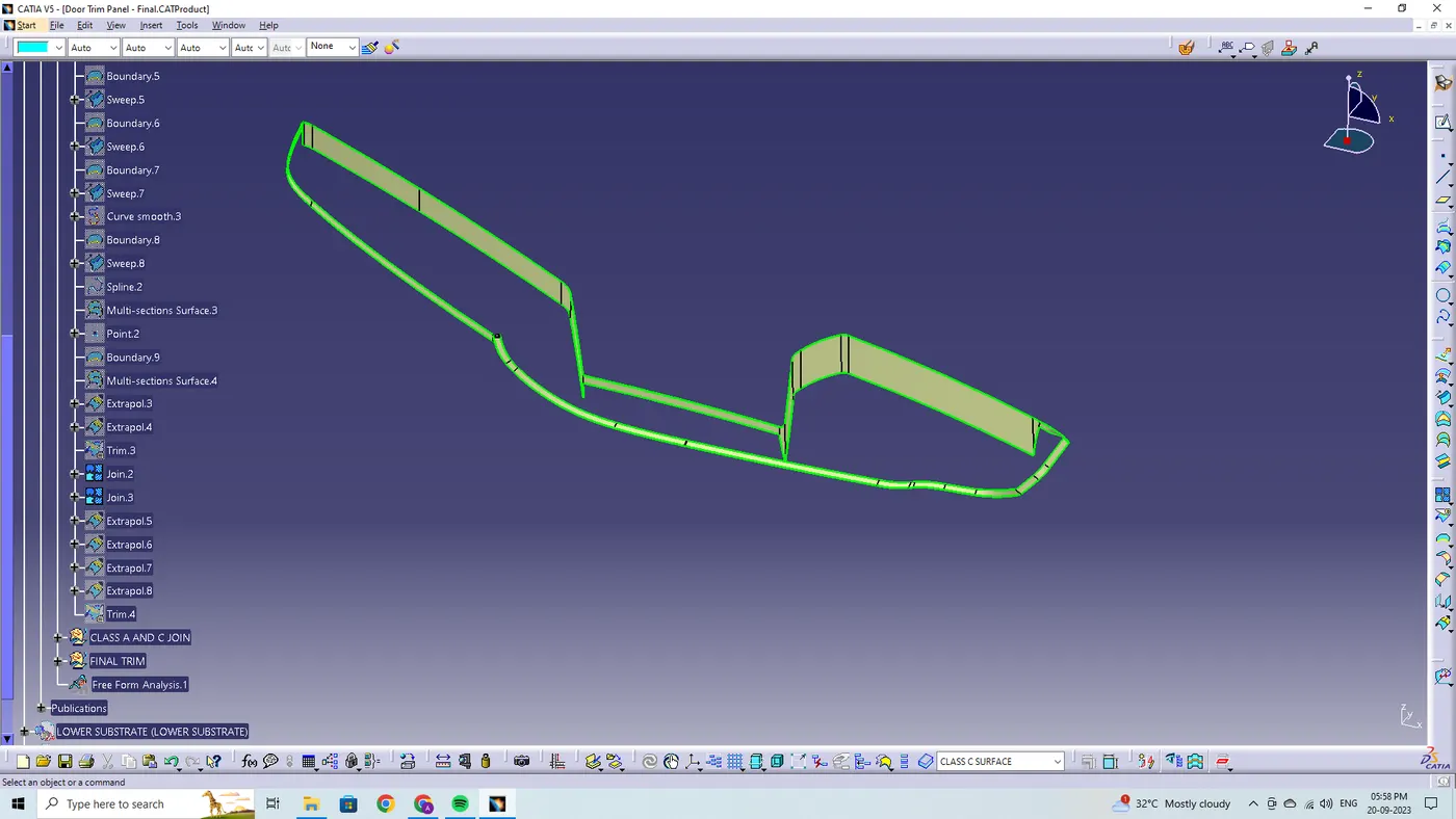
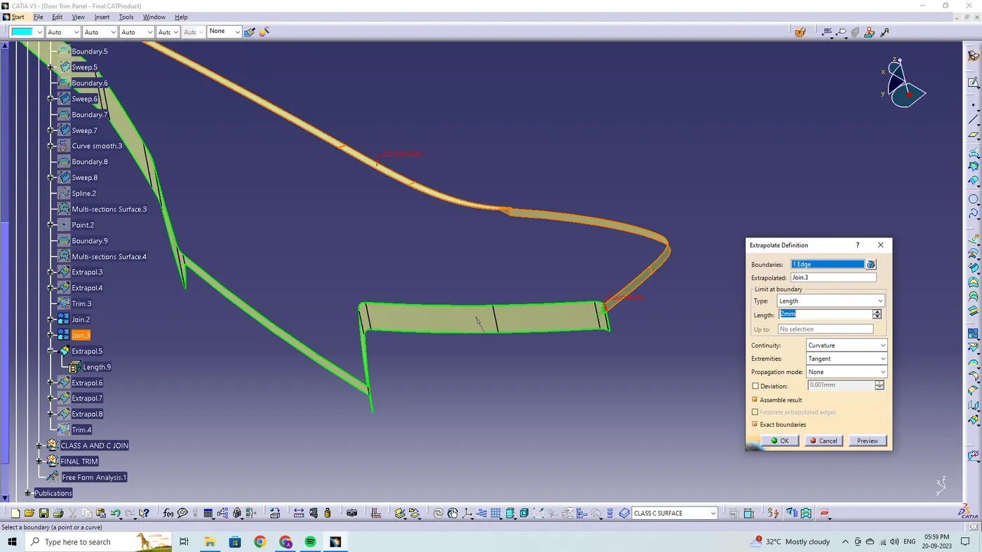
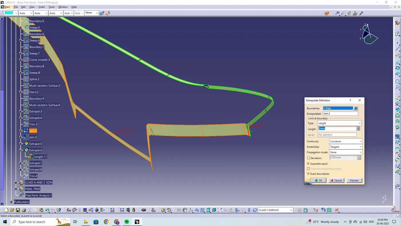
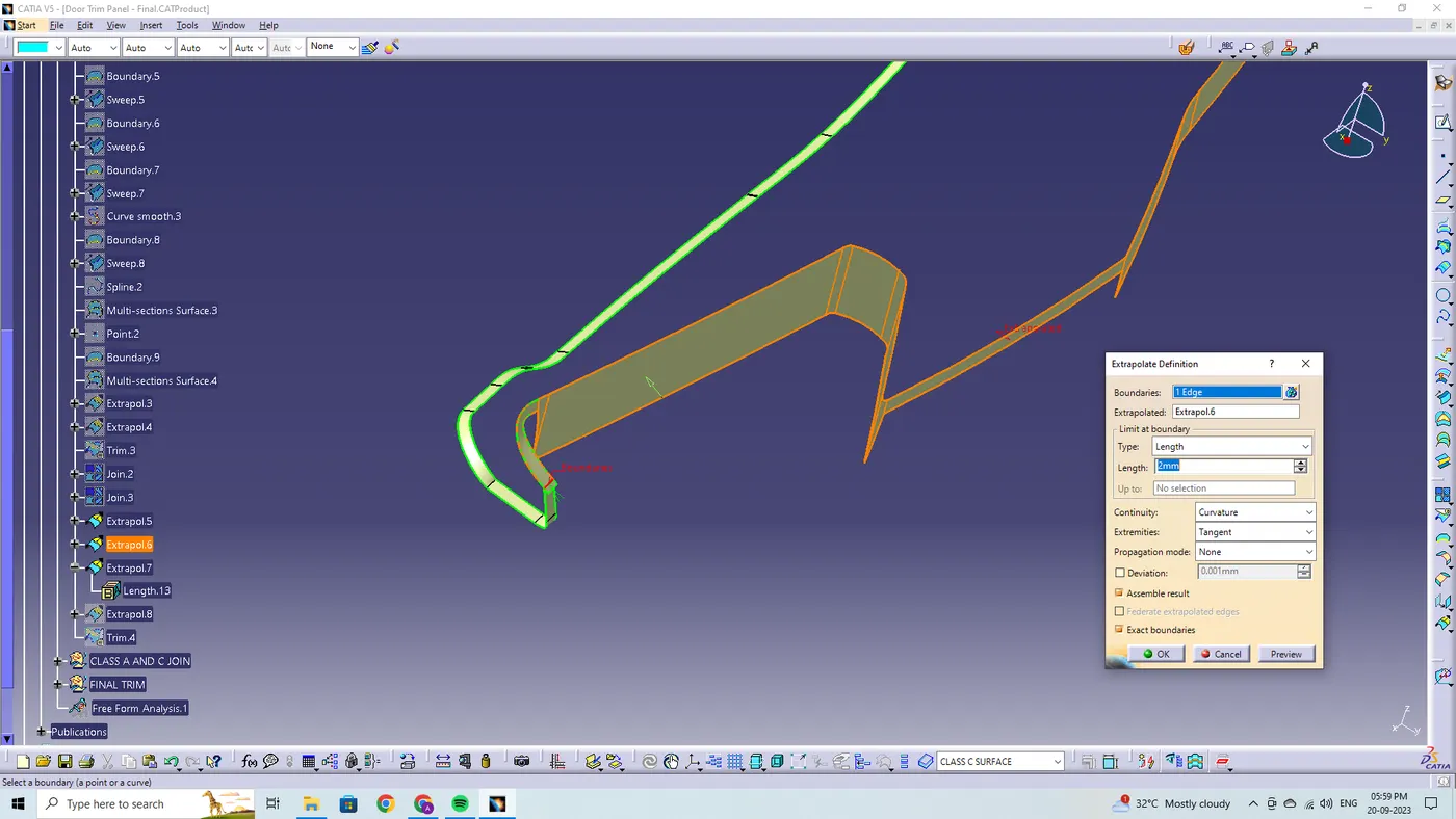
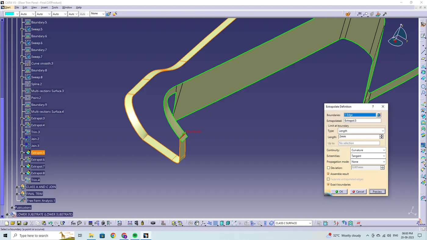
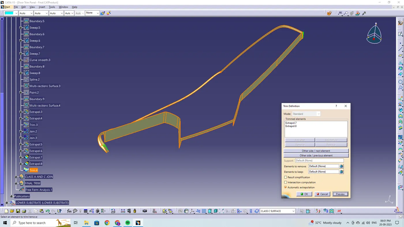
The class C surfaces are being created by using the sweep feature and the direction along the tooling direction and the reference with the surface and guide curve are being selected to form the class C surfaces.
JOINING THE CLASS A AND CLASS C SURFACES:
By using the join feature the class A and class C surface are joined together with the merging distance of 0.001 mm.
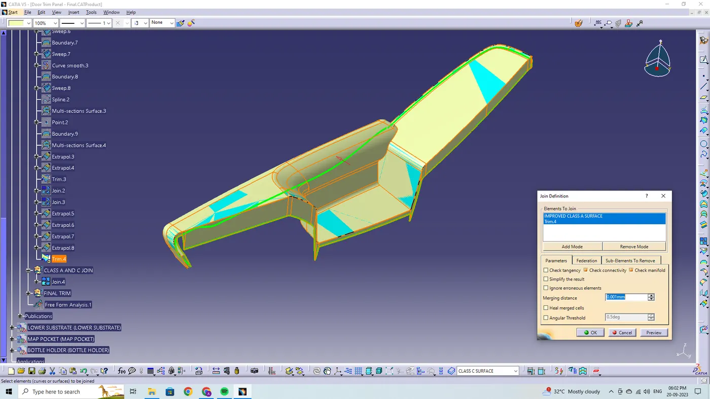
FINAL TRIMMING:
By using the intersection feature the first element and second element are being selected to check the intersection between the created class B and joined class (A+C).
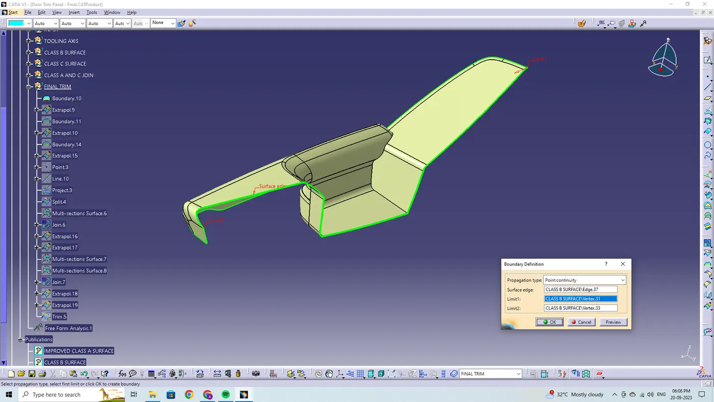
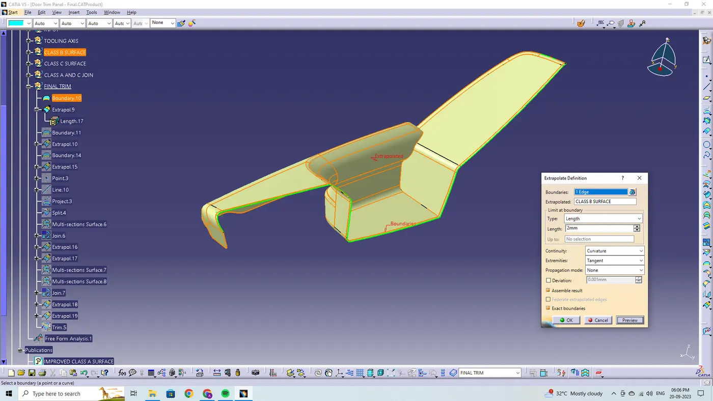
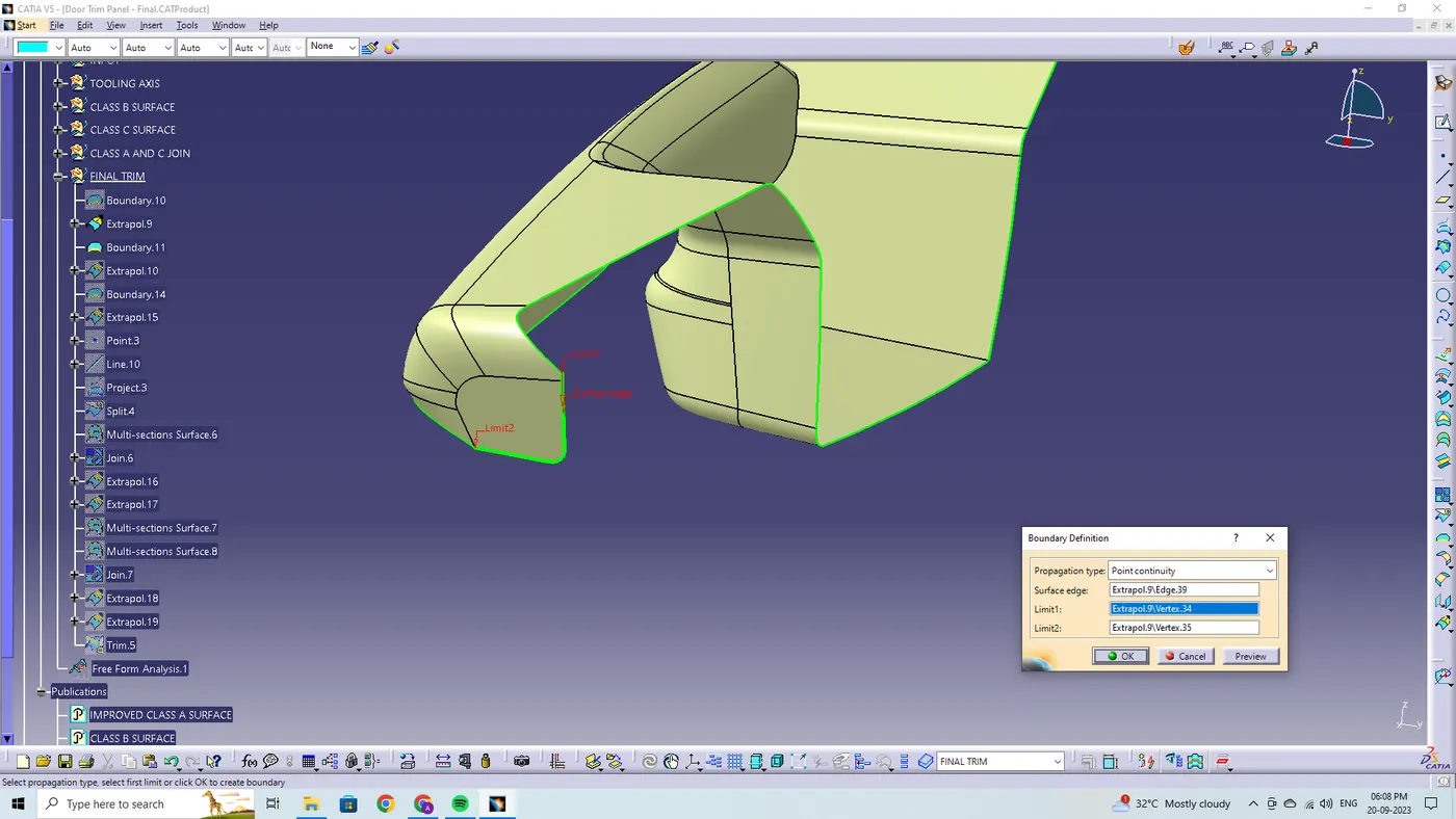
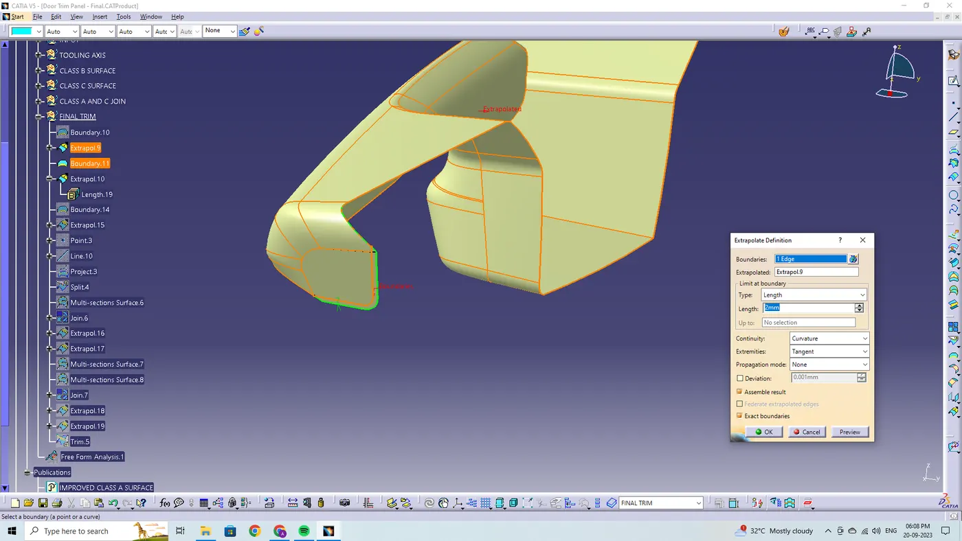
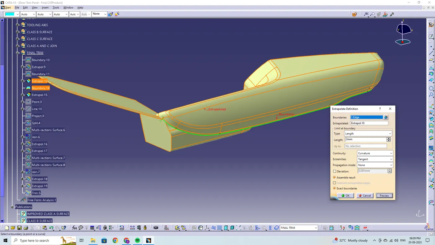
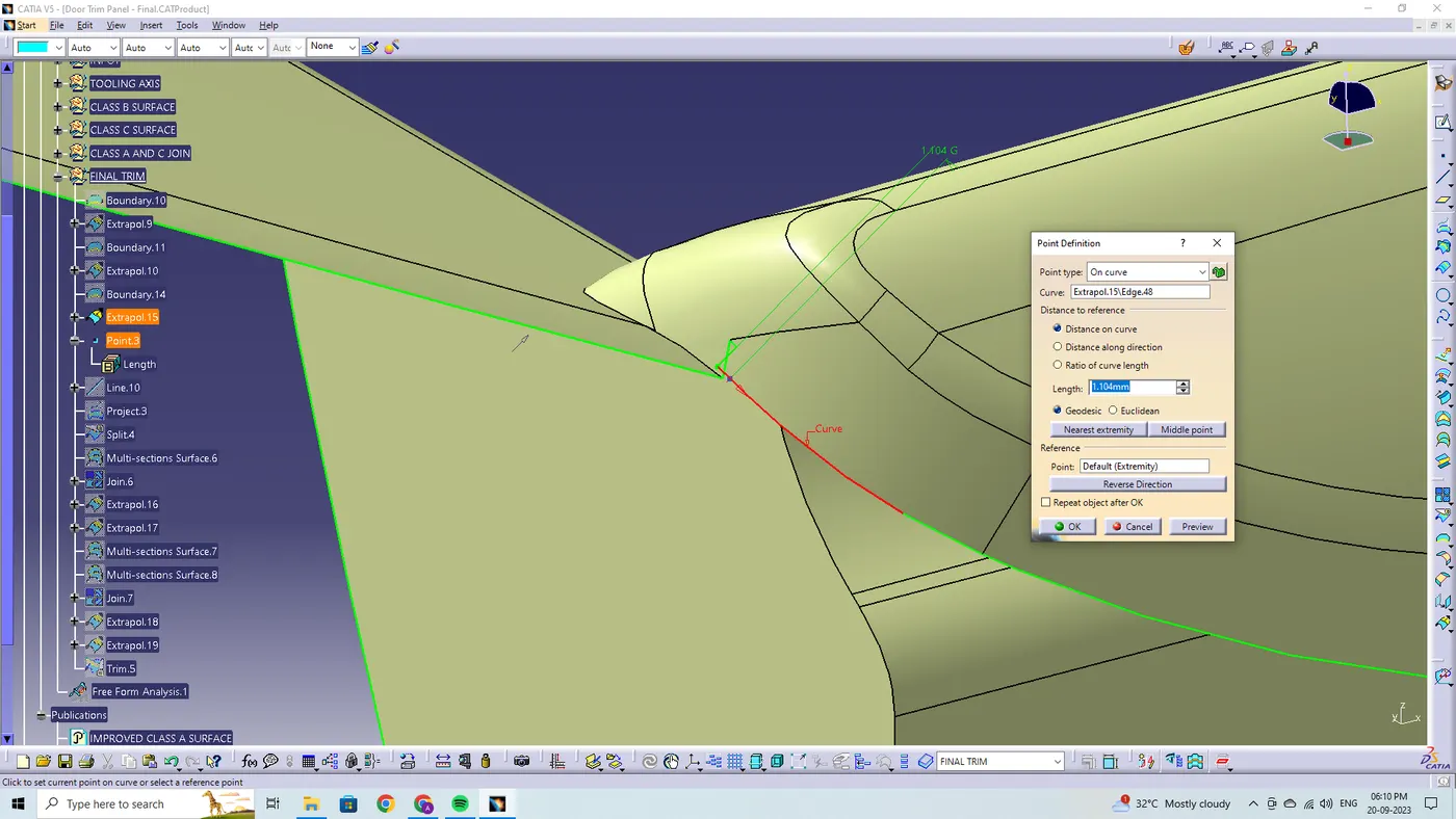
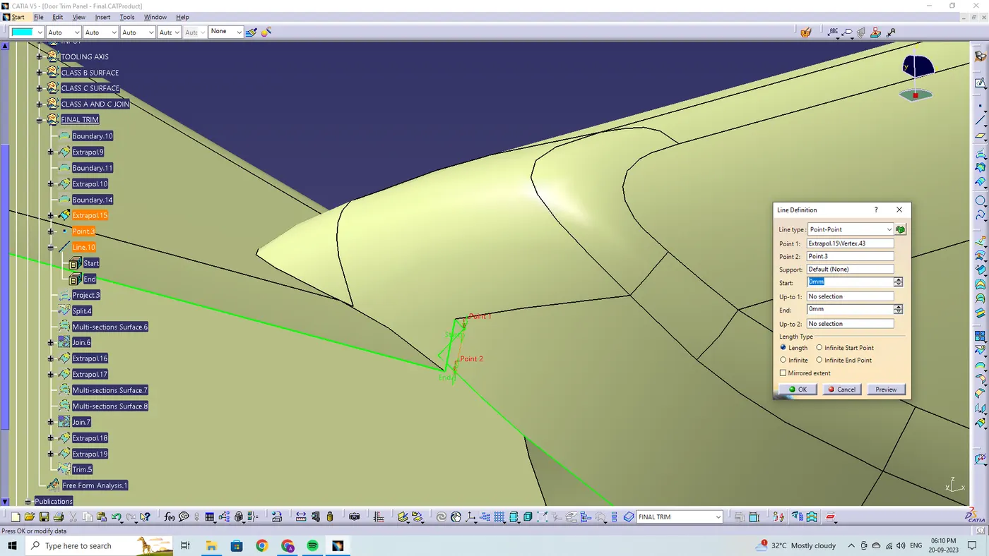
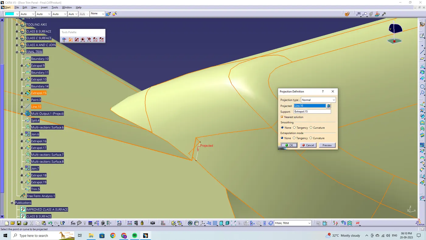
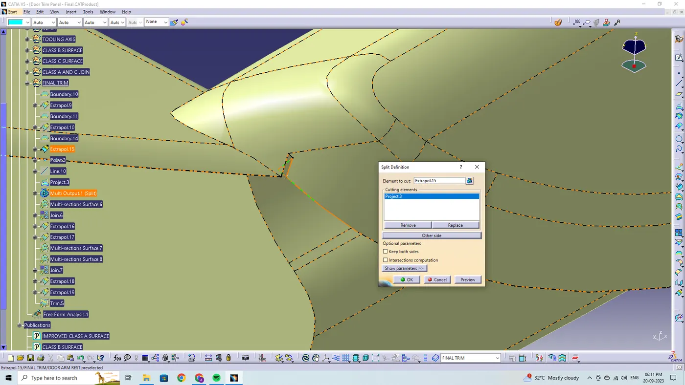
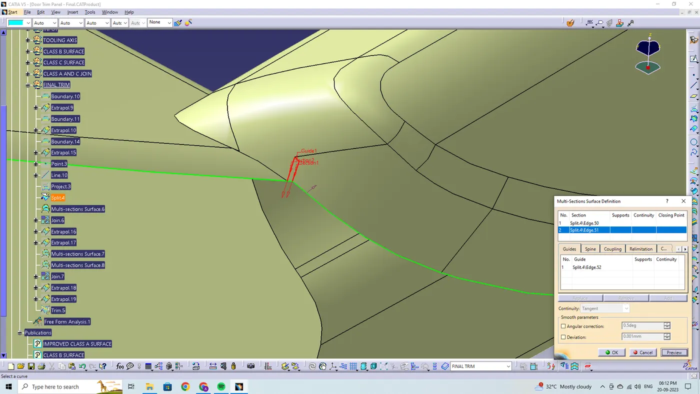
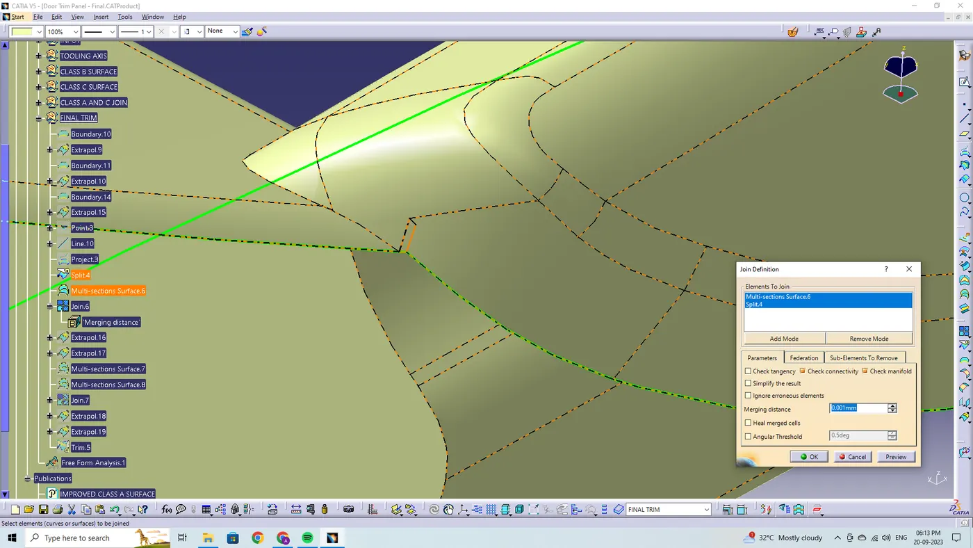
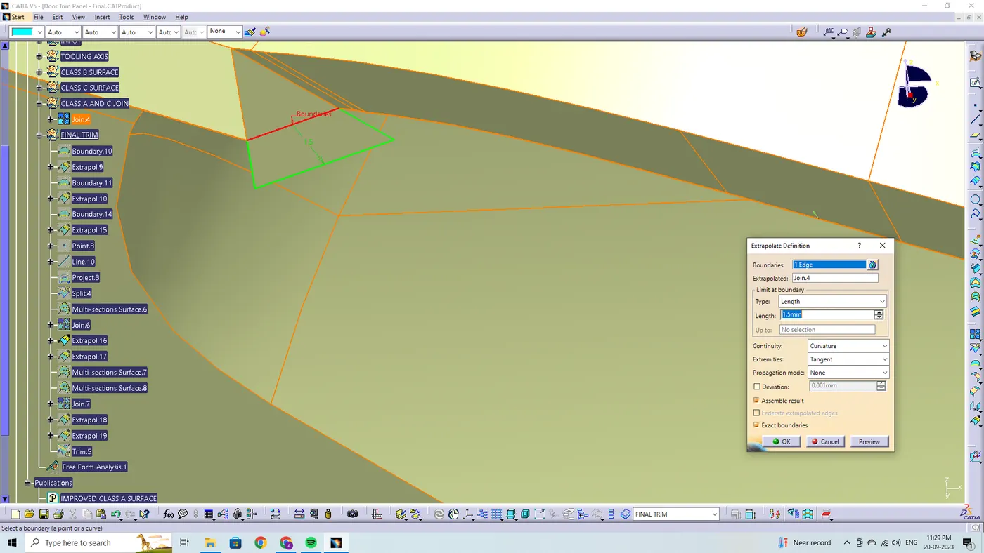
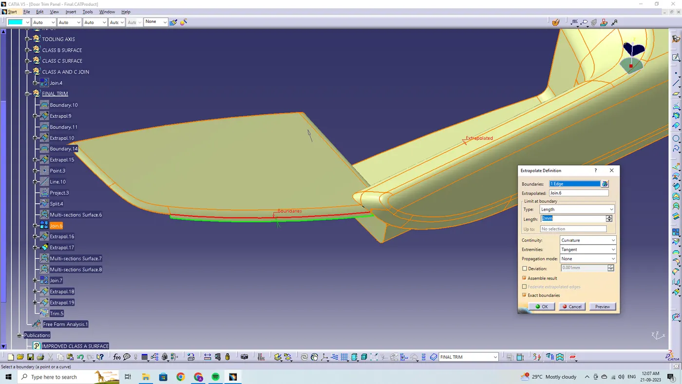
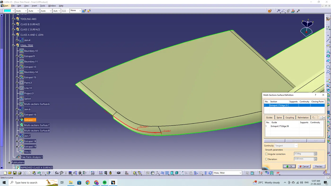
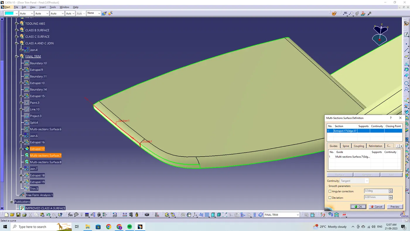
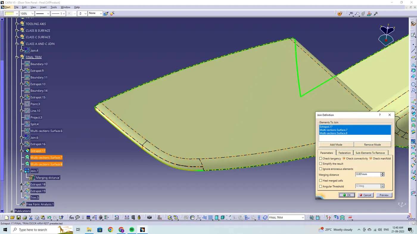
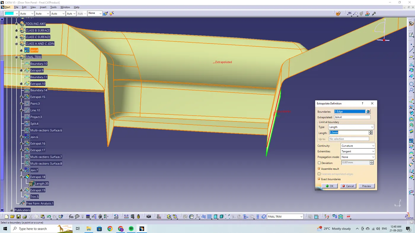
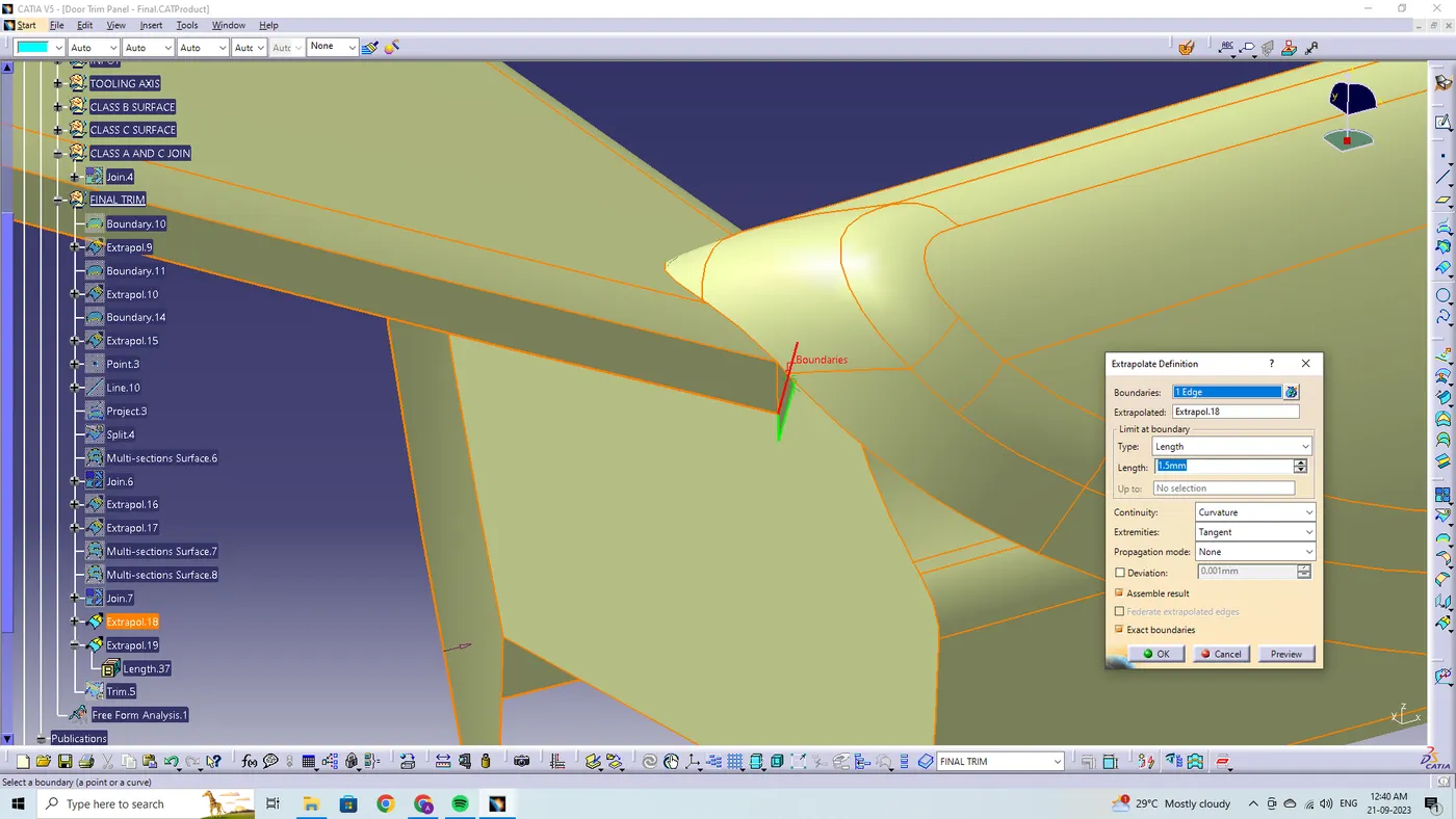
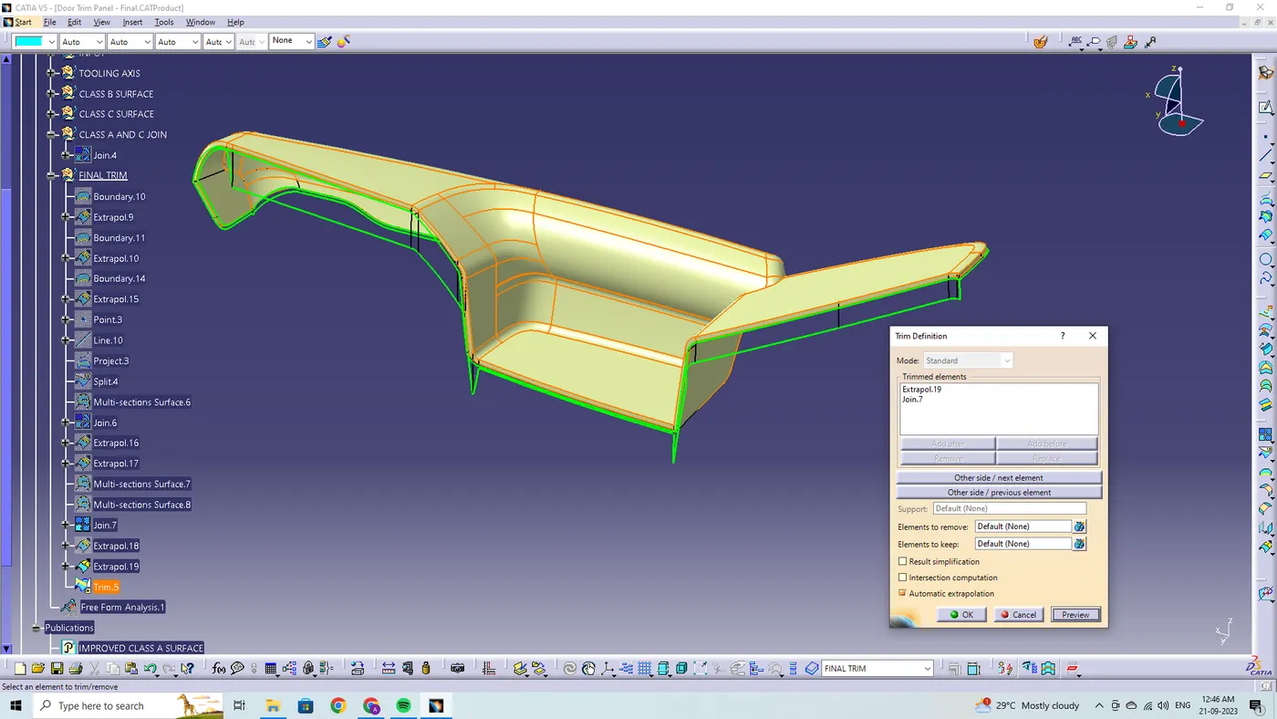
The final trimming has been performed on class B and joined class A and C surfaces. The trimming has been performed.
CLOSED SURFACE:
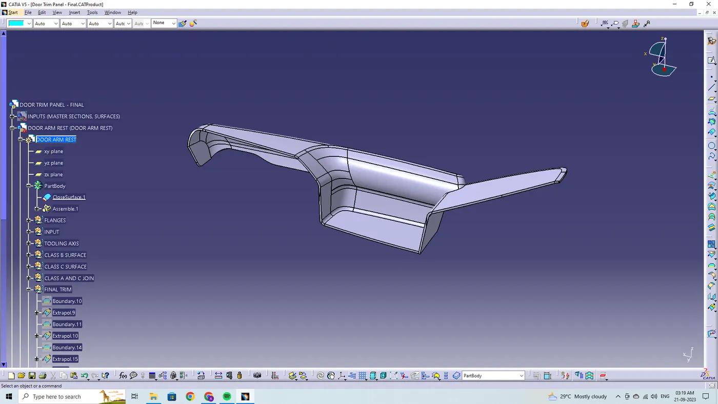
By using the close surface definition, the part surface is selected to make them into solid part from the part workbench.
DRAFT ANALYSIS:
The draft analysis has been performed on the final component created as a closed body using the part design closed surface feature. For plastic components the minimum angle required for the draft to be 3 degrees.
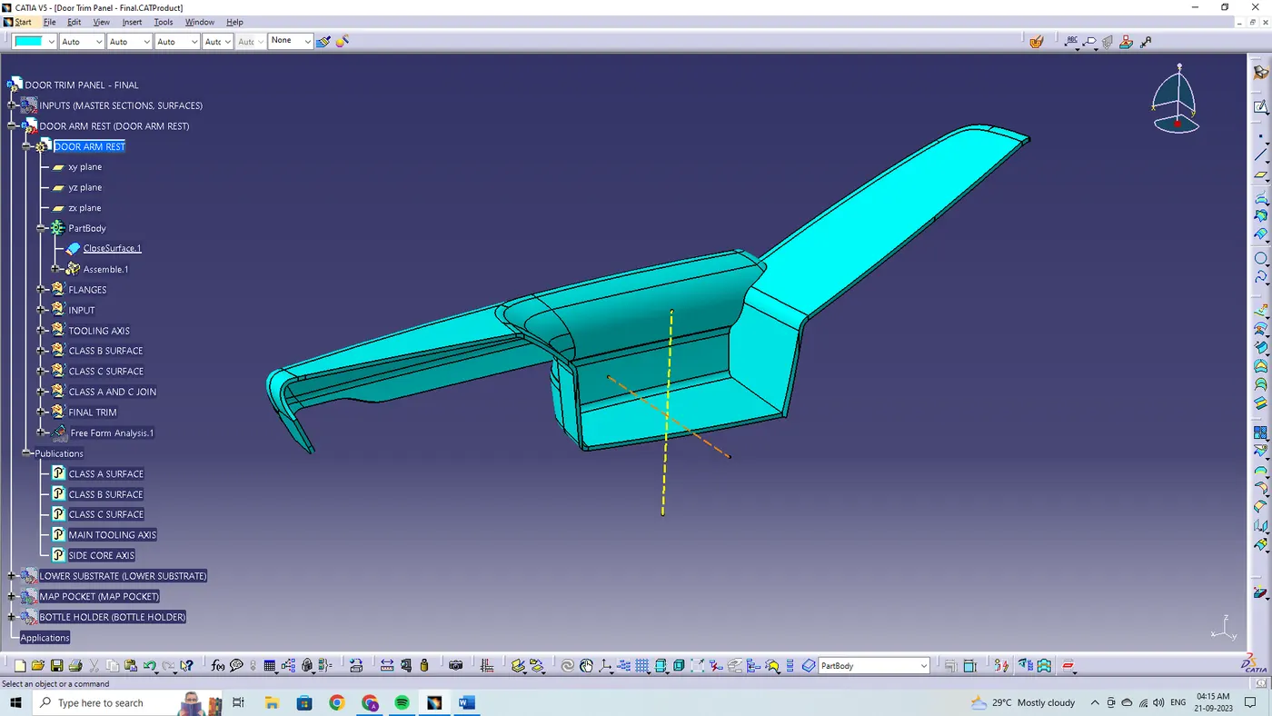
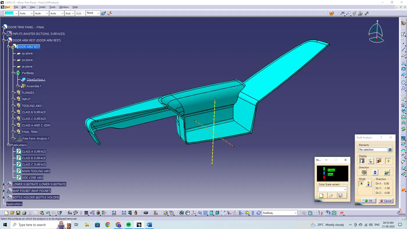
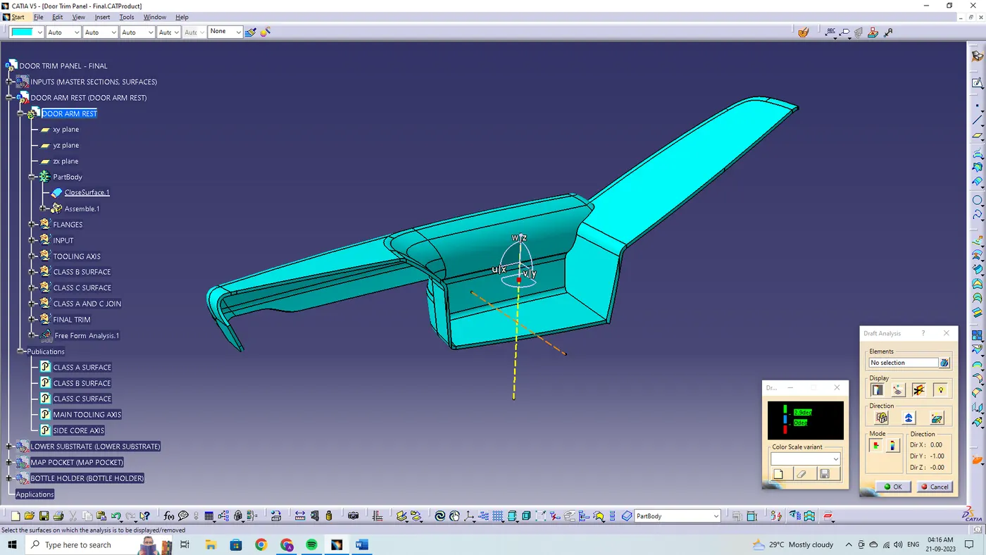
The direction compass is to be selected and placed it on the main tooling axis line and the compass is being locked using the lock feature in the directions.
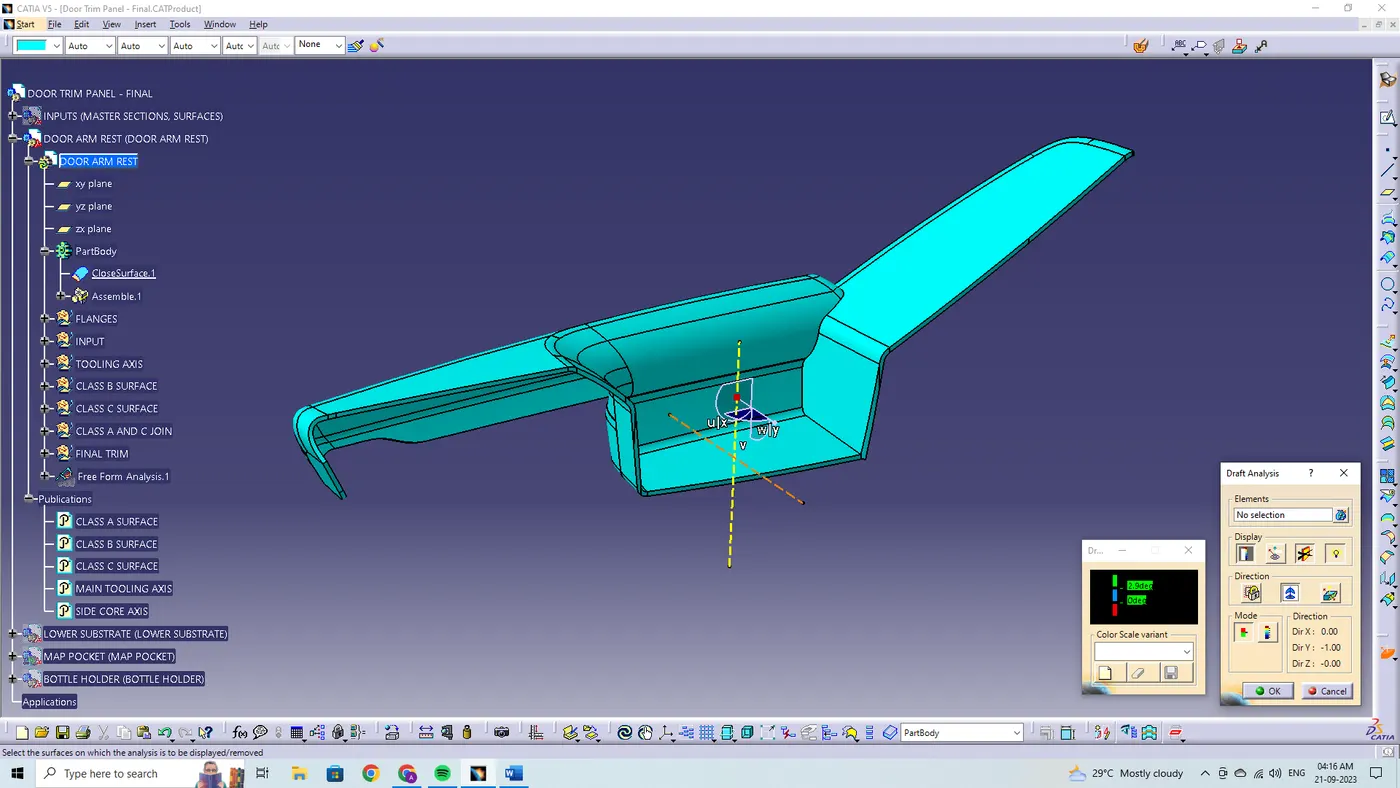
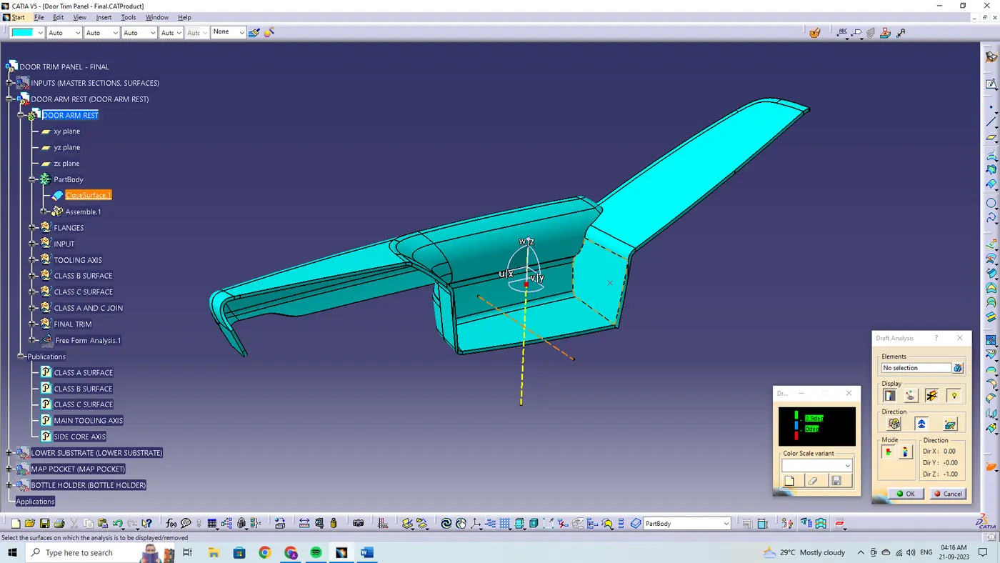
In the display window the colour code variants are being selected, to know the range of the draft in the class A surface. In the display window the colour variants show,
- For 3 degree - Green color variant (Positive)
- For 0 degree - Blue color variant
- For <0>
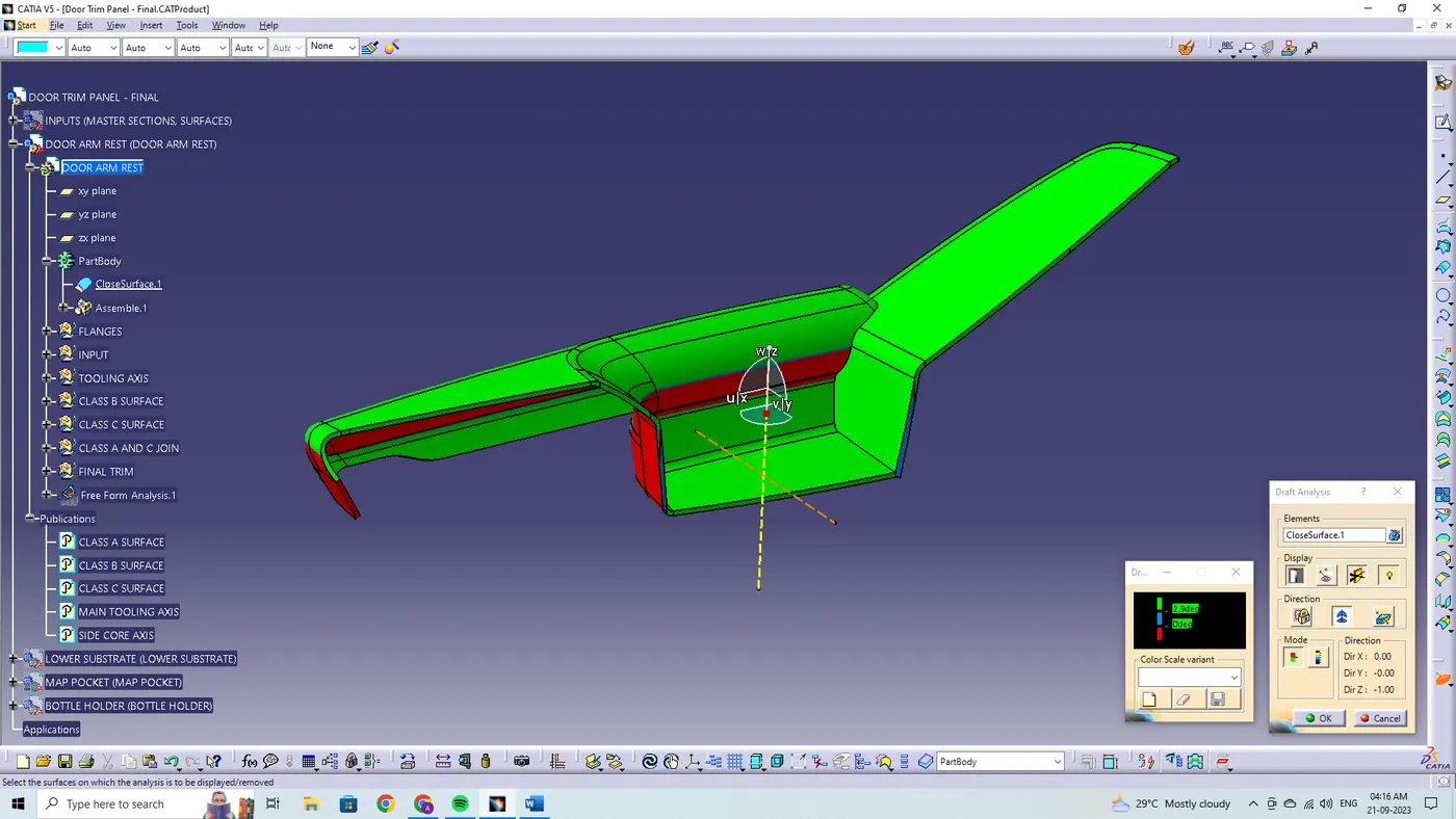
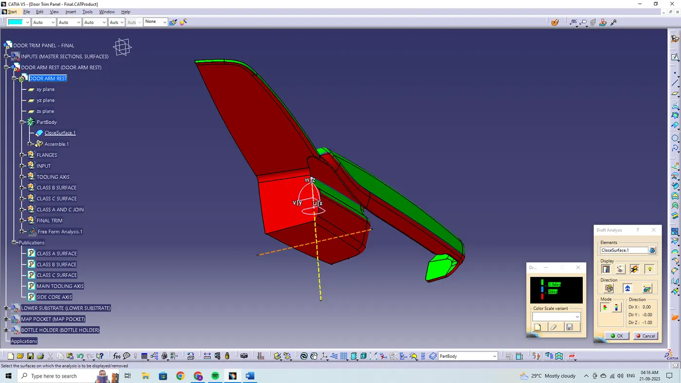
The side core tooling axis is created to clear the draft on the undercutted surfaces.
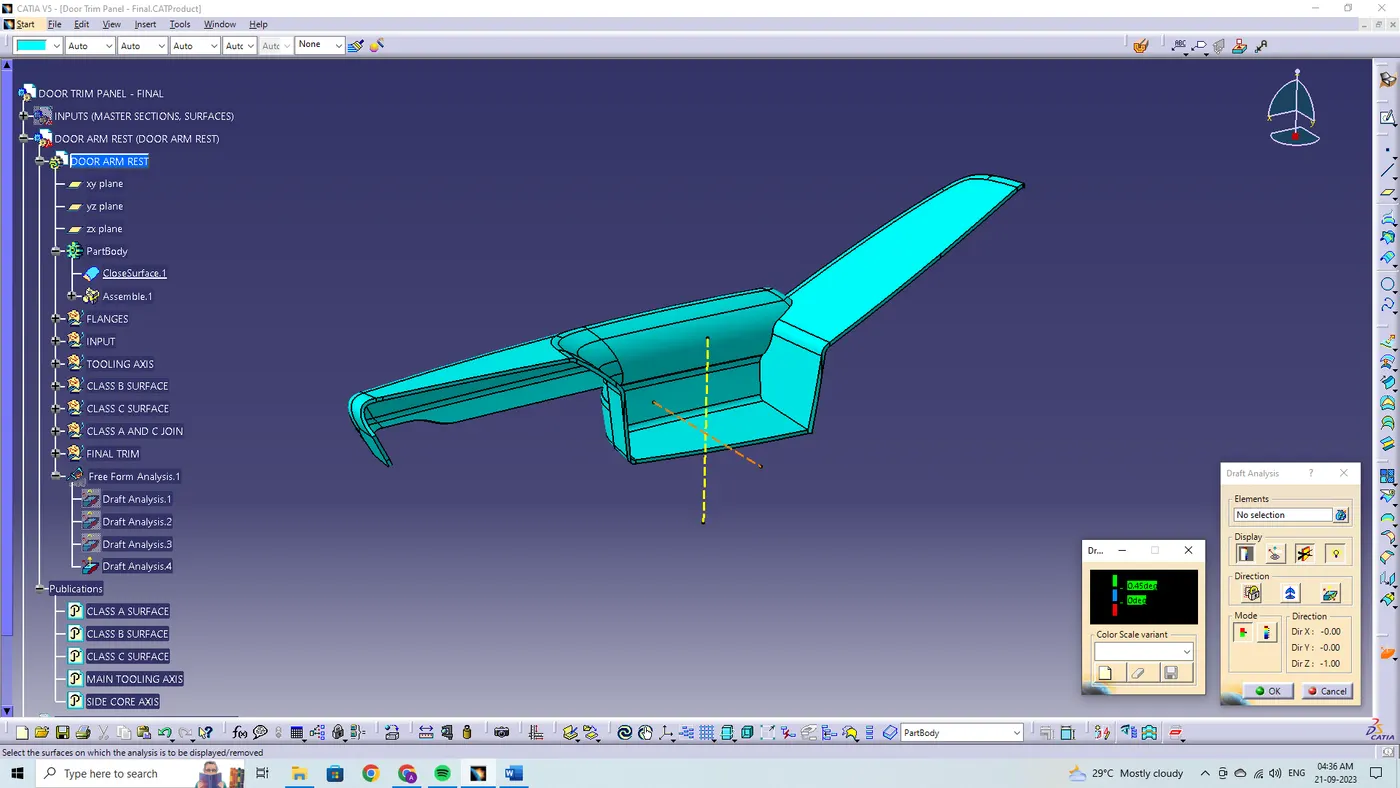
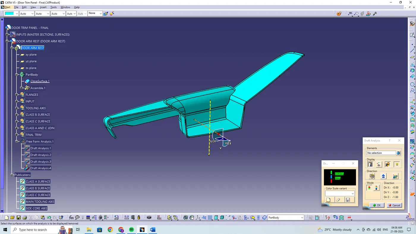
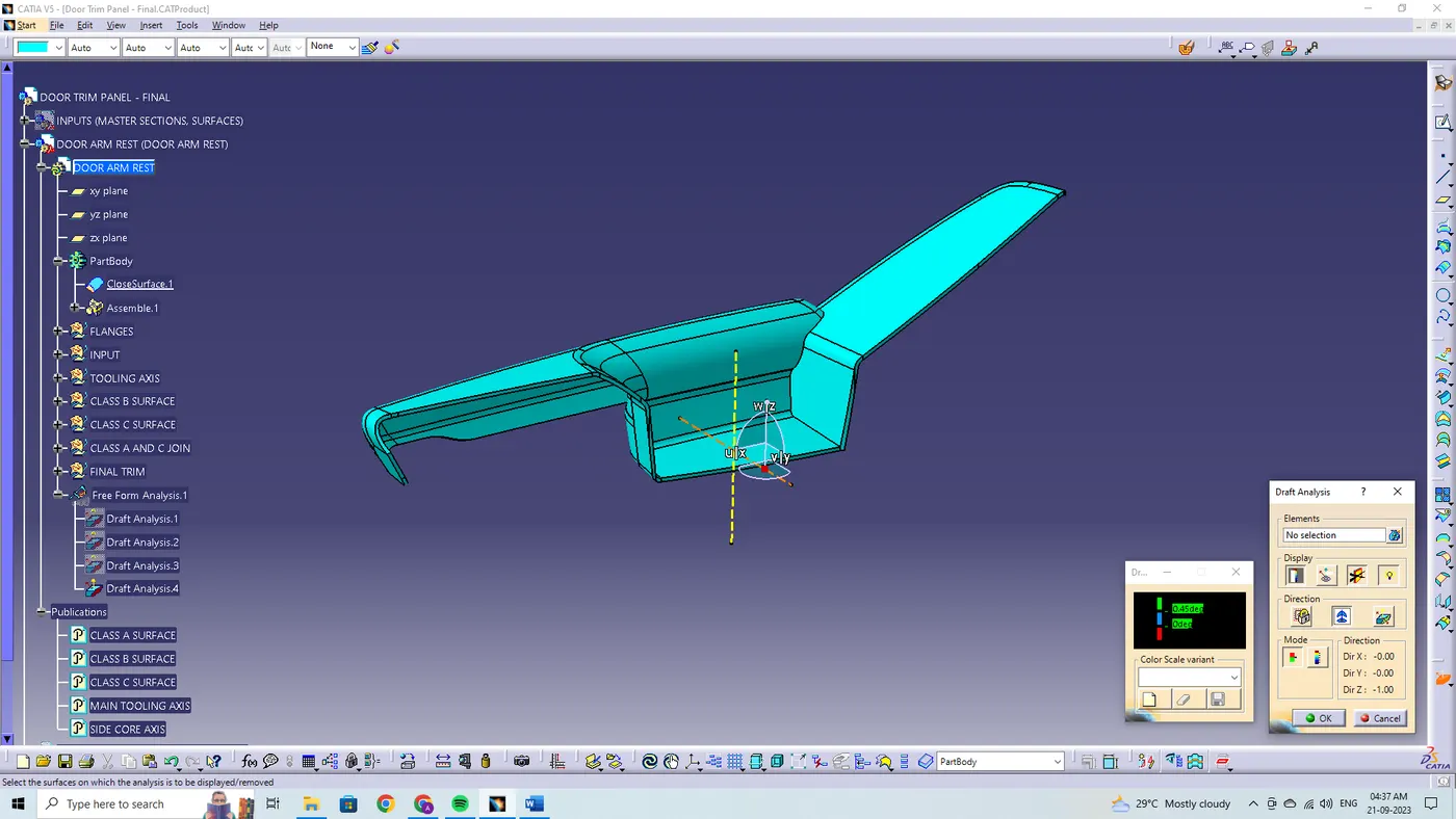
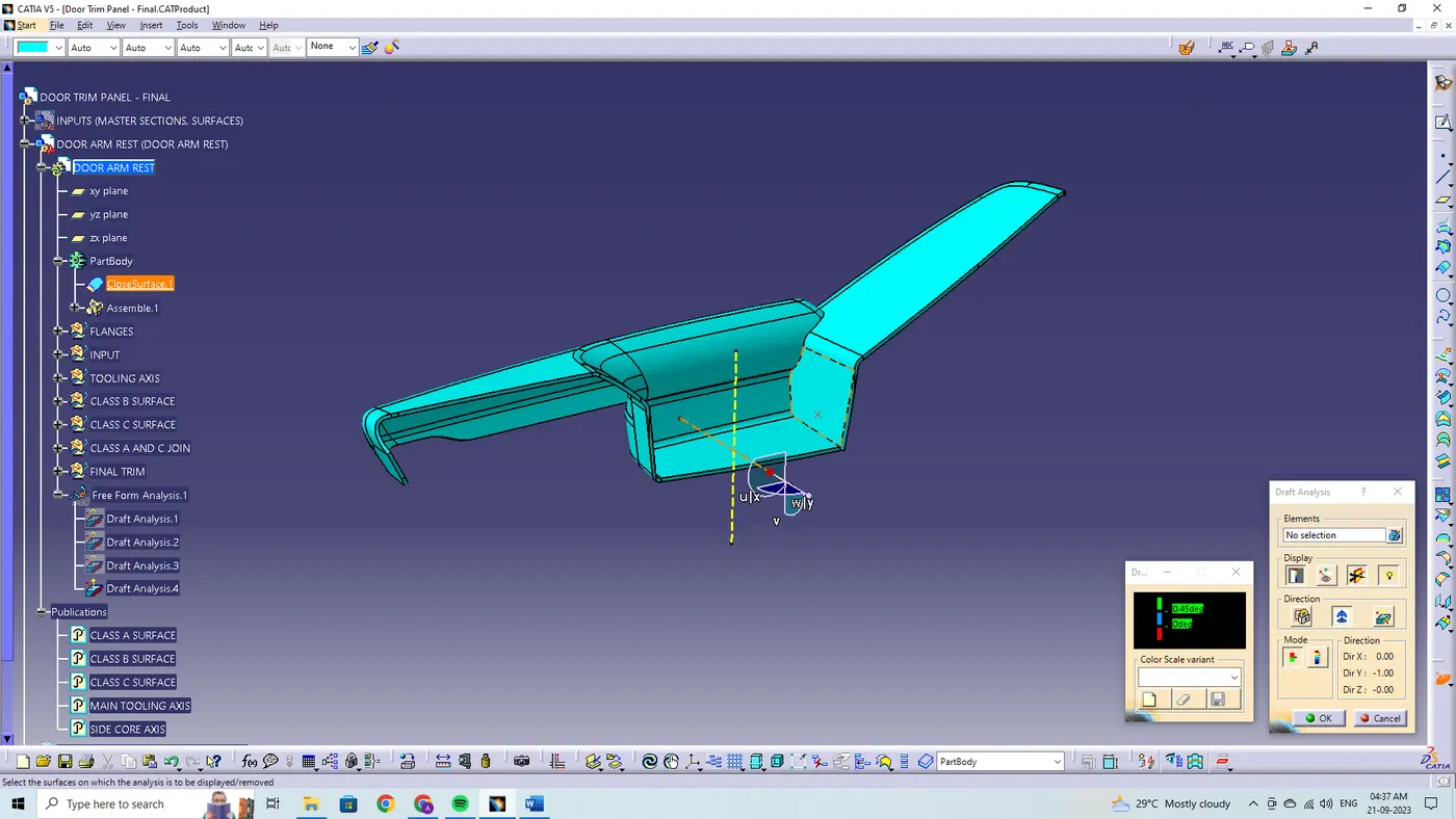
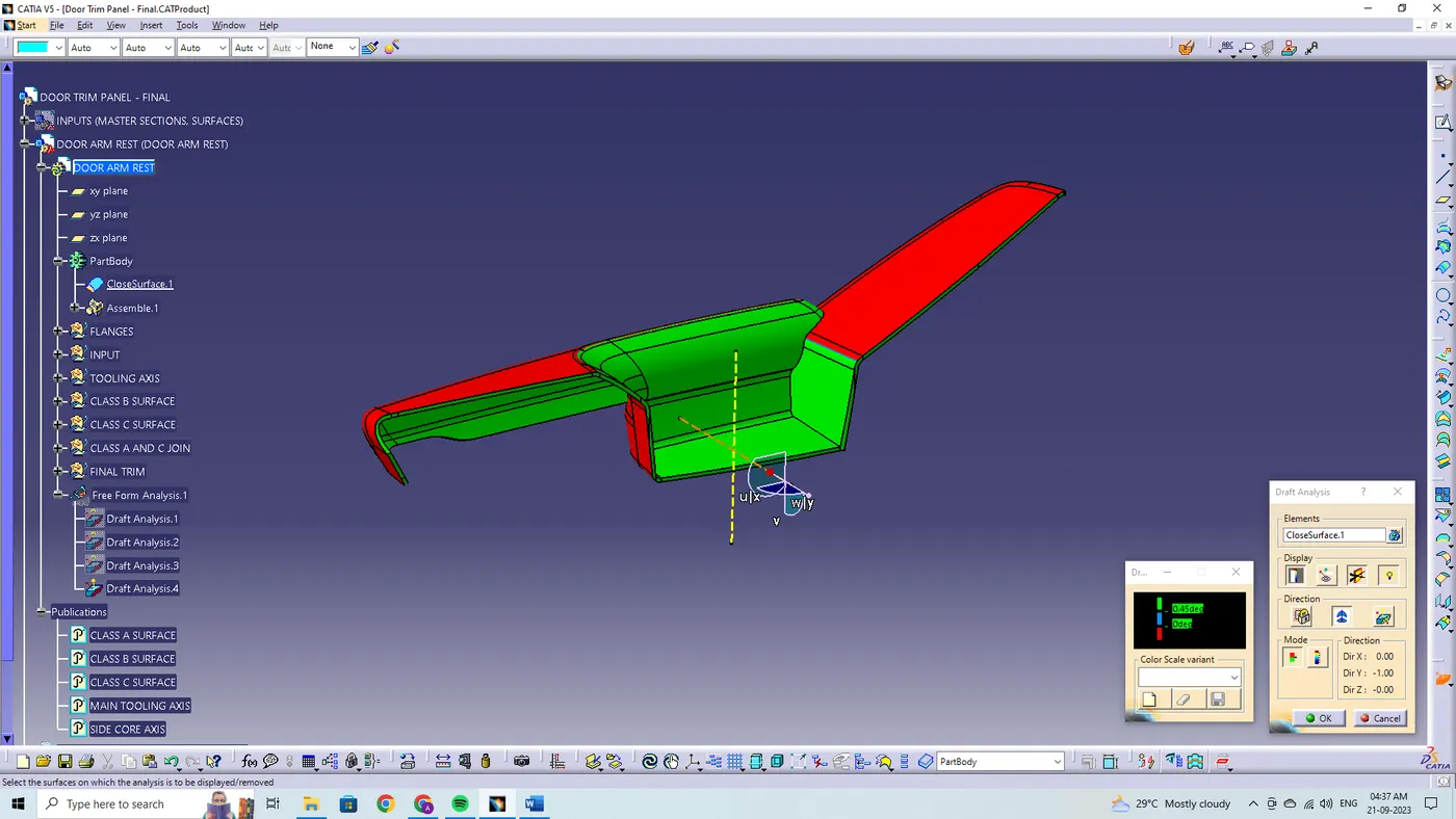
The draft analysis is being performed in both the core and cavity side of solid body. The green colour implies the draft angle are in the positive region. If the draft angle is being inverted the colour of the surface are implied as blue colour.
LOWER SUBSTRATE
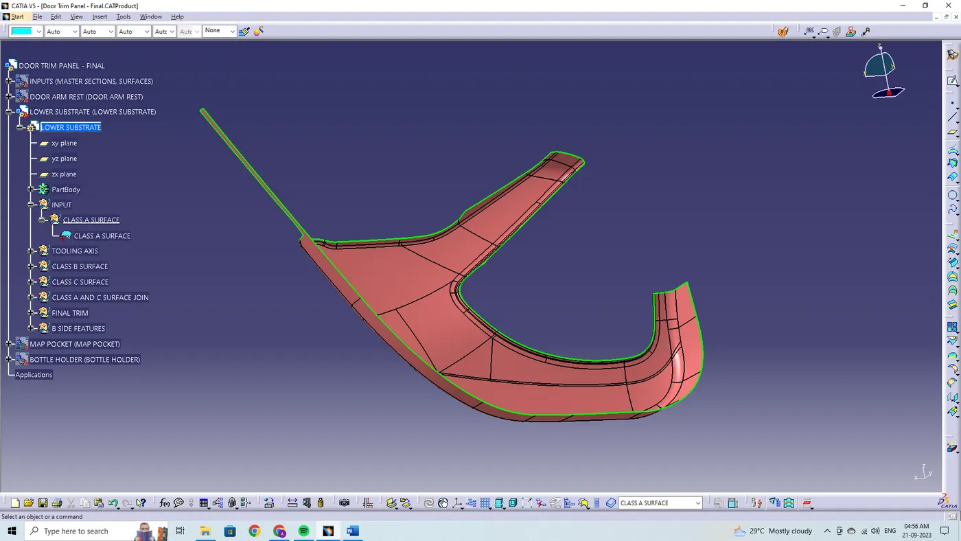
CLASS A SURFACES:
DESIGN CHECK:
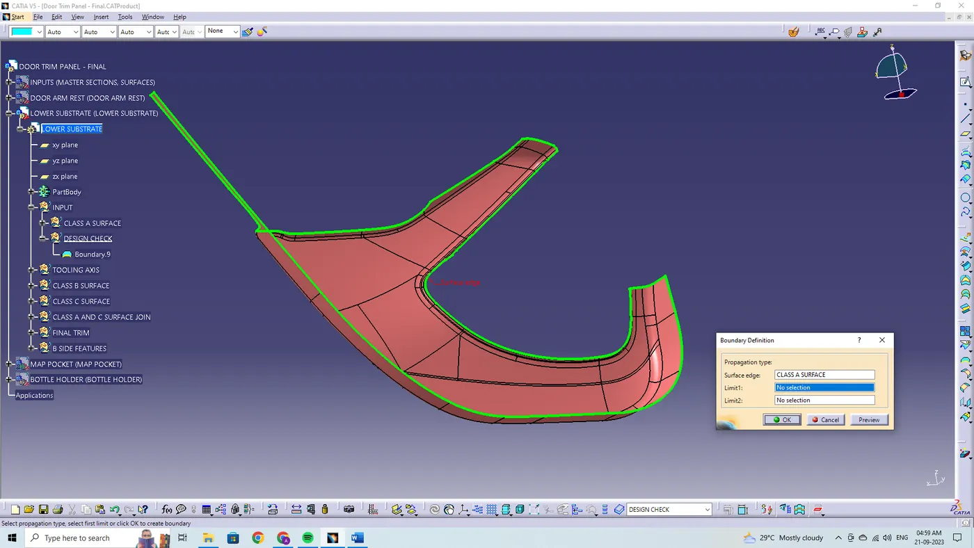
The class A surface is checked visually by using the join feature or by using the boundary feature the class A surface is selected and disassembled the surface to check the surface are created without the gaps. The class A surface should be created without boundary gaps. By using the join definition with the merging distance of 0.001 mm the class A surface is joined together to check the connectivity.
CREATING TOOLING AXIS:
The tooling for the class A surface is created in the direction in which the parts are ejected from the tool. The tooling axis which defines the core and cavity pulls apart from the tooling direction.
Along the x,y,z co-ordinate system the surfaces (Surfaces are likely to see visually) are selected.
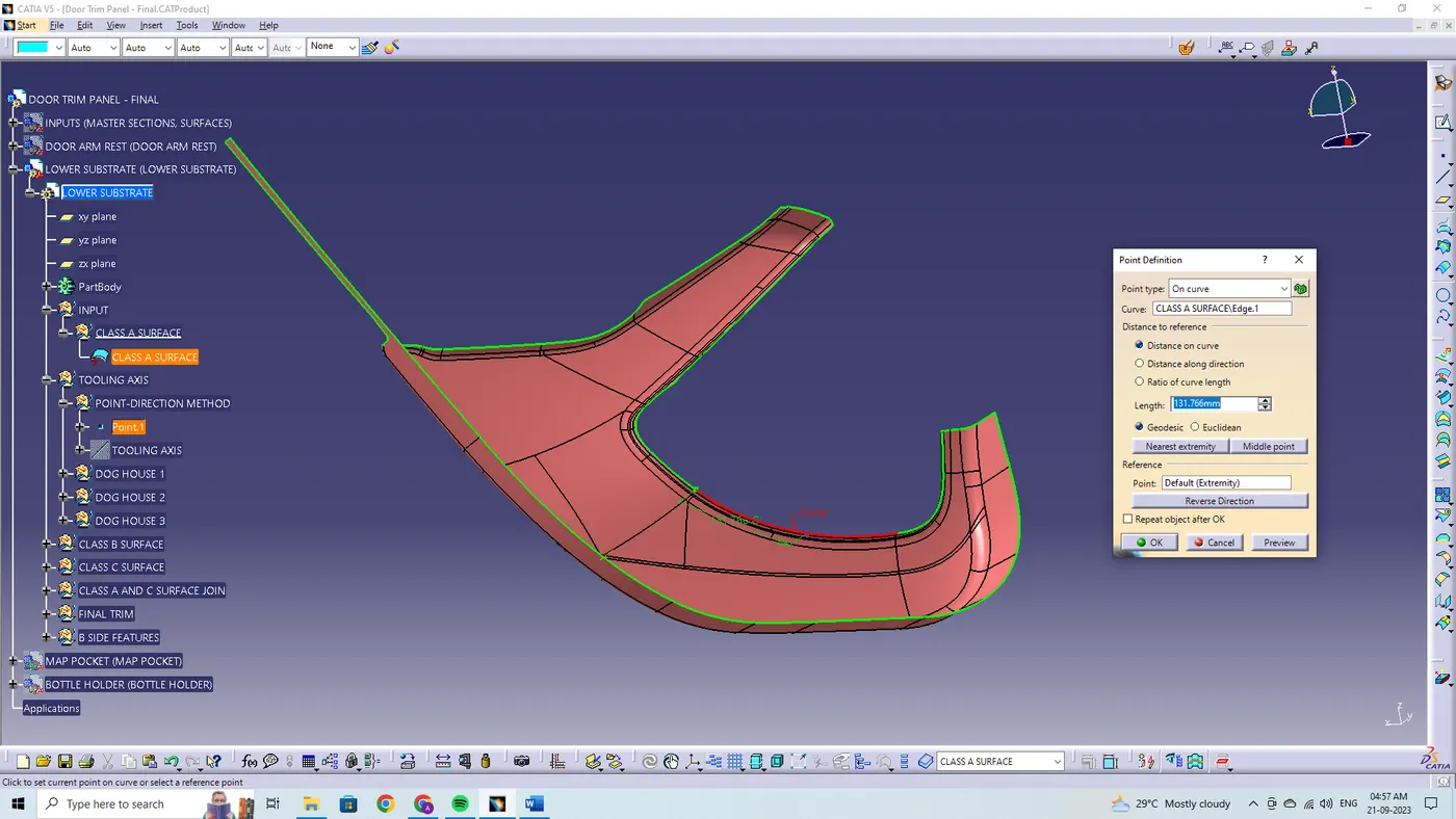
By using the point definition, the point has been created on surface midpoint along Y- direction.
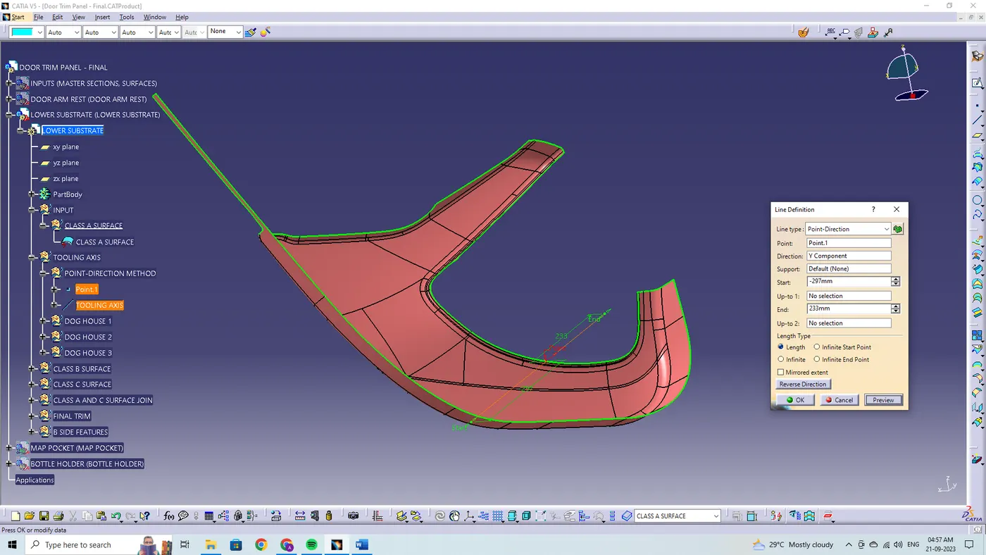
The main tooling axis has been created using the line definition feature. From the line type point direction, point has been selected and direction along Y component are selected to define the line.
DRAFT ANAYSIS:
For a class A surface, the draft analysis is to be performed to meet the requirement of the draft angle to the required tooling axis. For plastic components the minimum angle required for the draft to be 3 degrees.
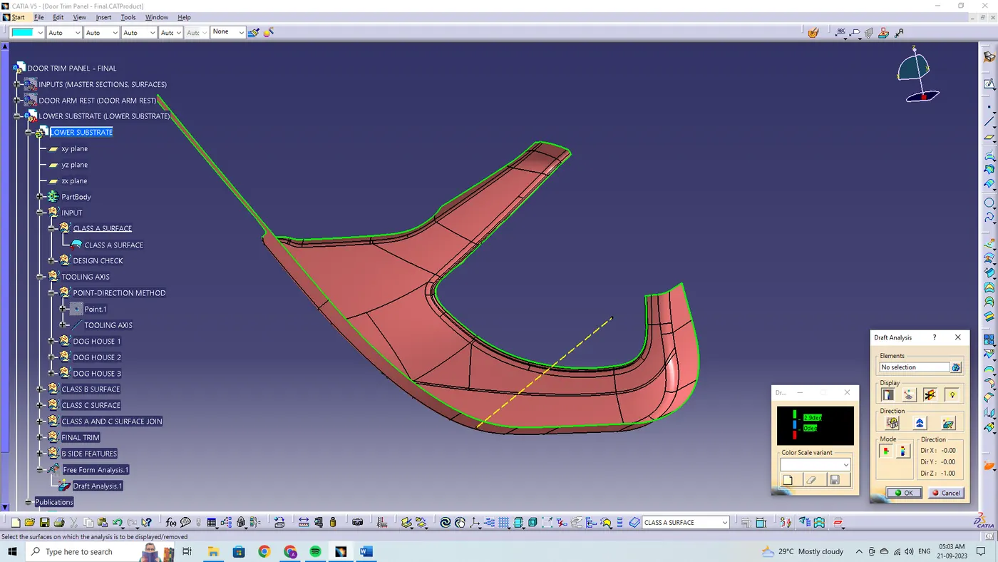
The direction compass is to be selected and placed on the main tooling axis line and the compass is being locked using the lock feature in the direction.
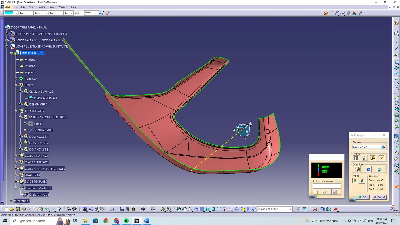
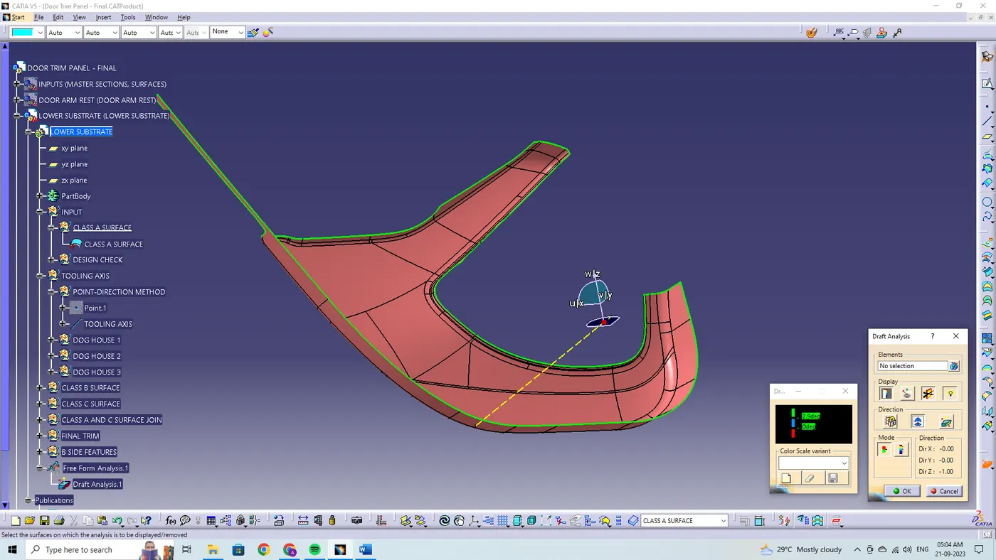
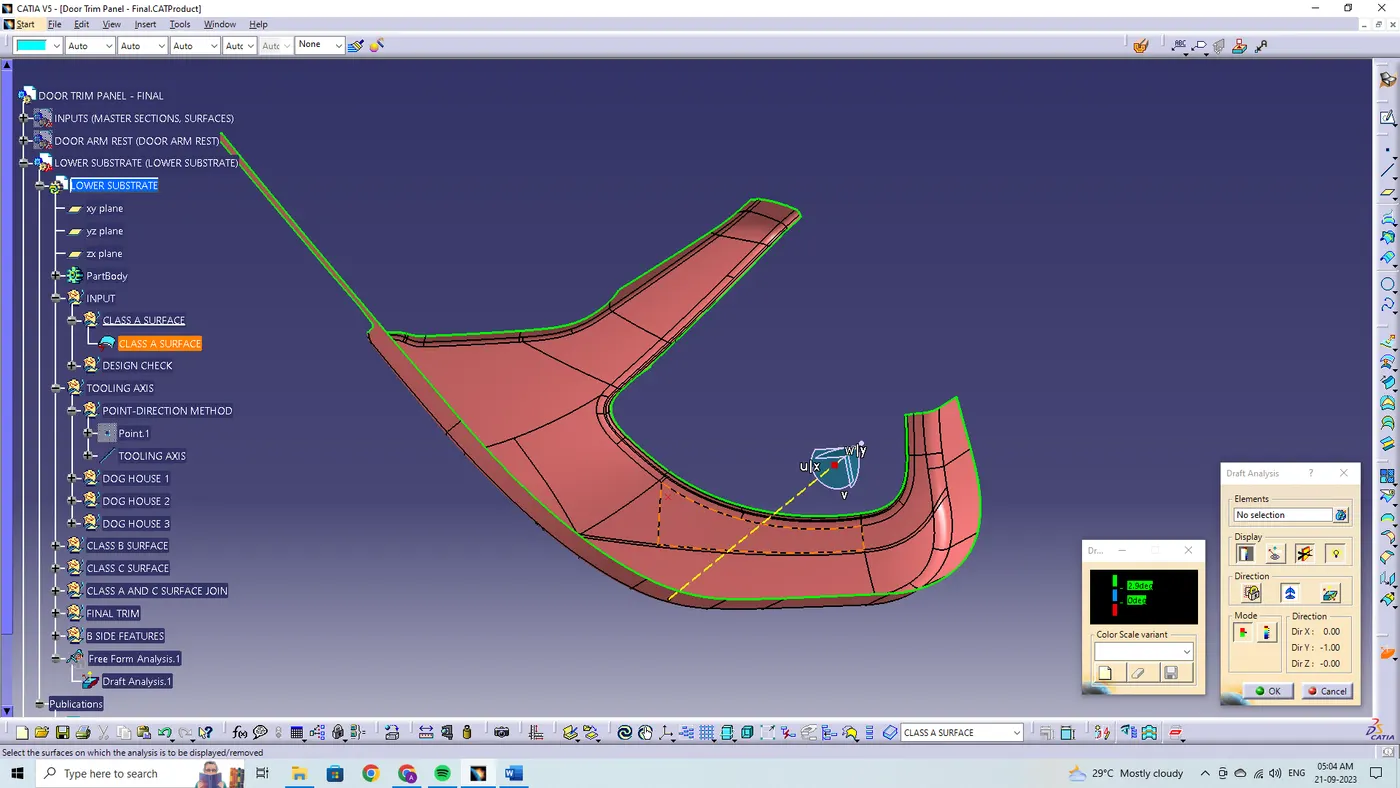
In the display window the colour code variants are being selected, to know the range of the draft in the class A surface. In the display window the colour variants show,
- For 3 degree - Green color variant (Positive)
- For 0 degree - Blue color variant
- For <0>
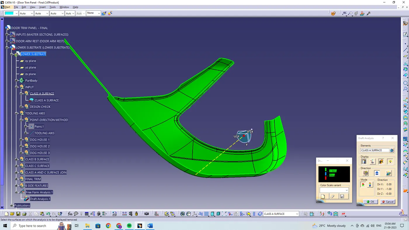
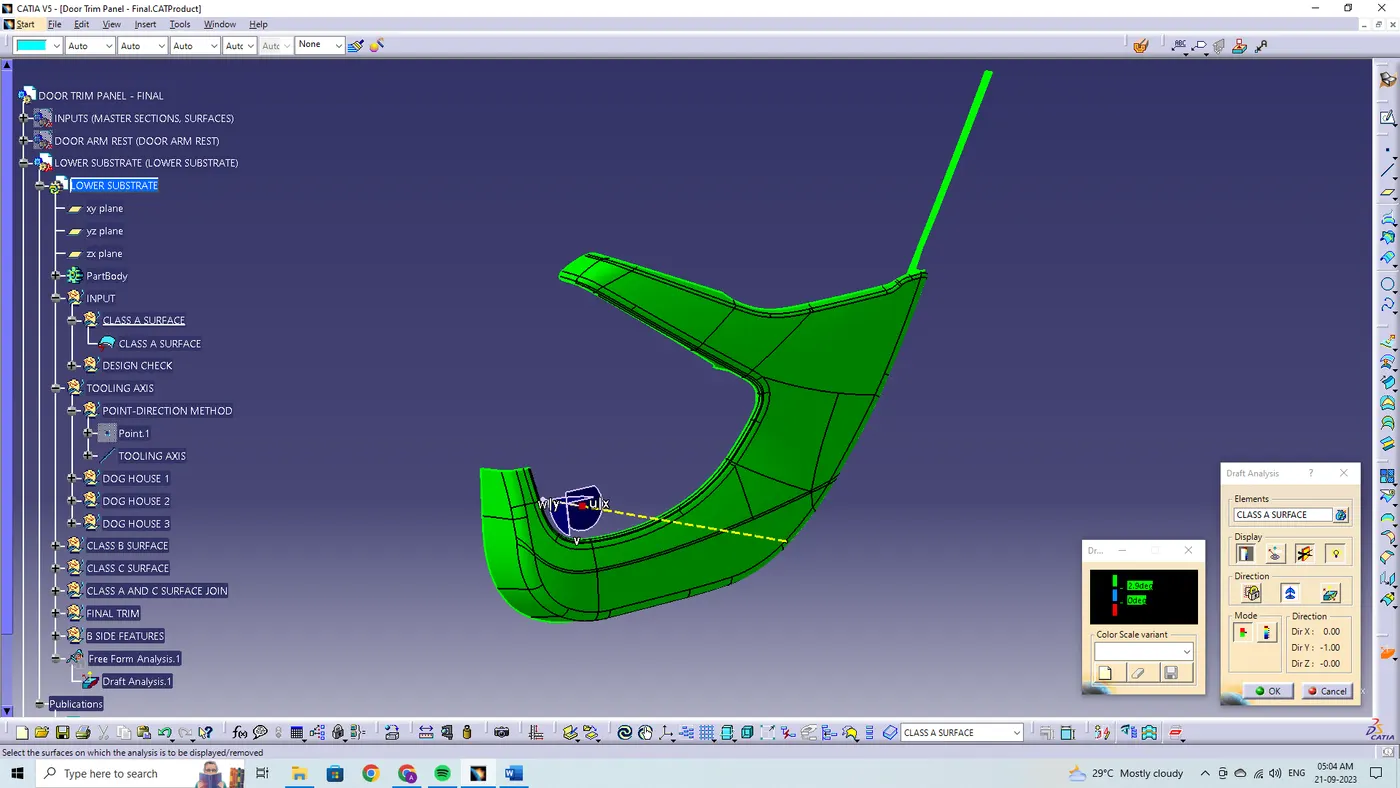
The draft analysis is being performed in both the core and cavity side of solid body. The green colour implies the draft angle are in the positive region. If the draft angle is being inverted the colour of the surface are implied as blue colour.
CREATION OF CLASS 'B' SURFACE:
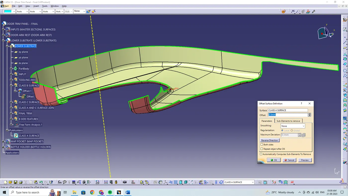
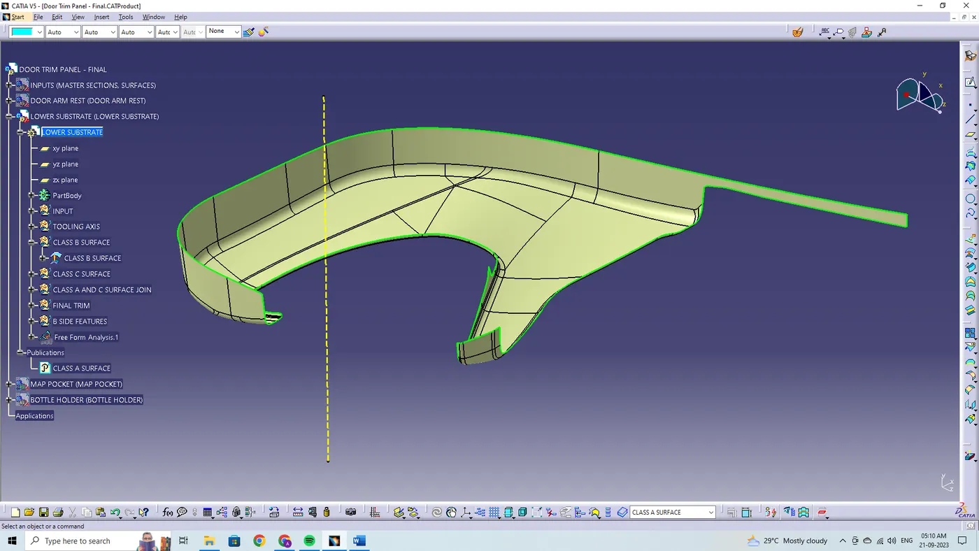
By using the class A surface, the class B surface is created by offsetting to the respective length to the respective direction. By using the offset surface definition the class A surface are been offset to the length of 2.5 mm to the respective direction.
CREATING CLASS 'C' SURFACE:
To make the class C surface, the boundaries are extracted from the class A surface. The outer boundary is being extracted using the boundary feature/extract definitions.
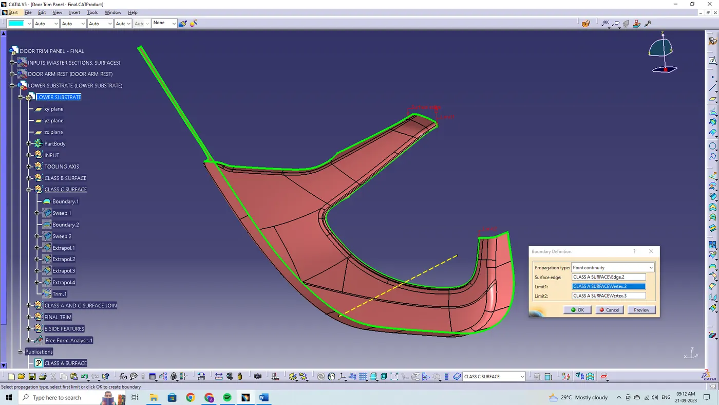
By using the sweep surface creation definition, the respective profile types are being selected and subtype with reference surface are being selected. In that the guide curve are selected as the boundary in the class A surface, and reference surface are selected, and the class C surface are being created to the respective length.
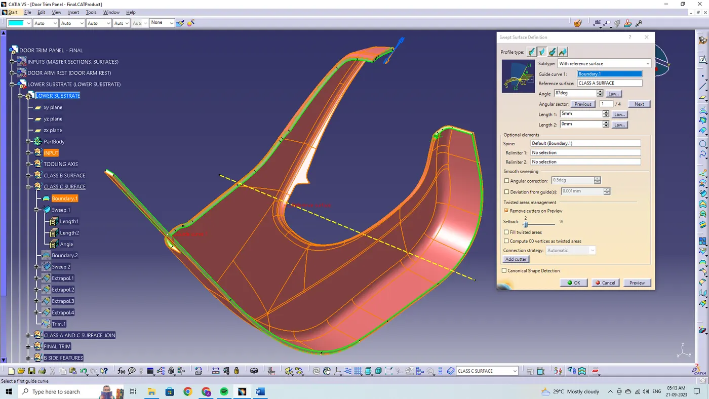
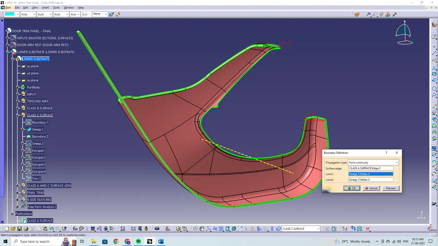
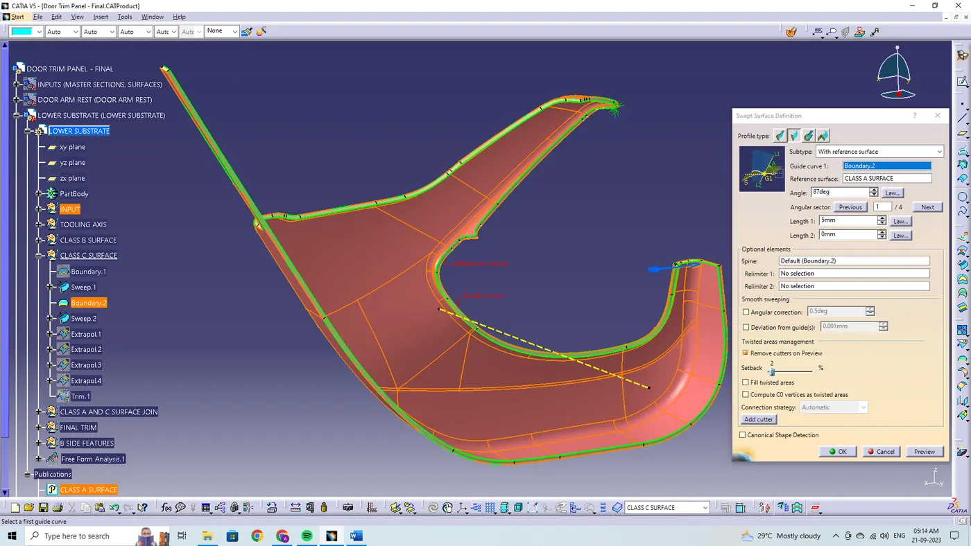
By using the join definition feature the created class C surfaces are being joined together, and by using the extrapolation and trimming feature the edges are being extrapolated and trimmed together to form the class C surfaces.
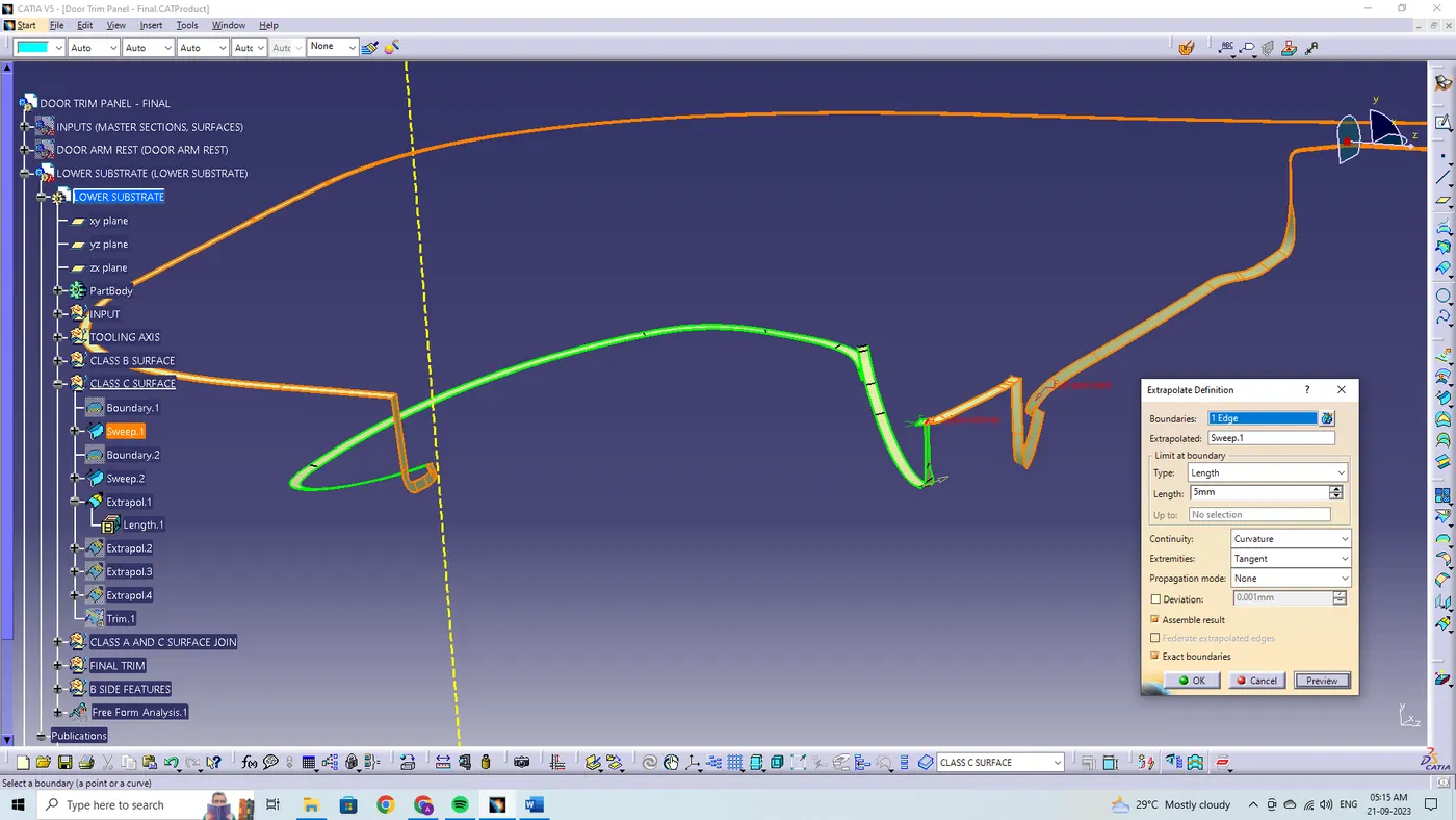
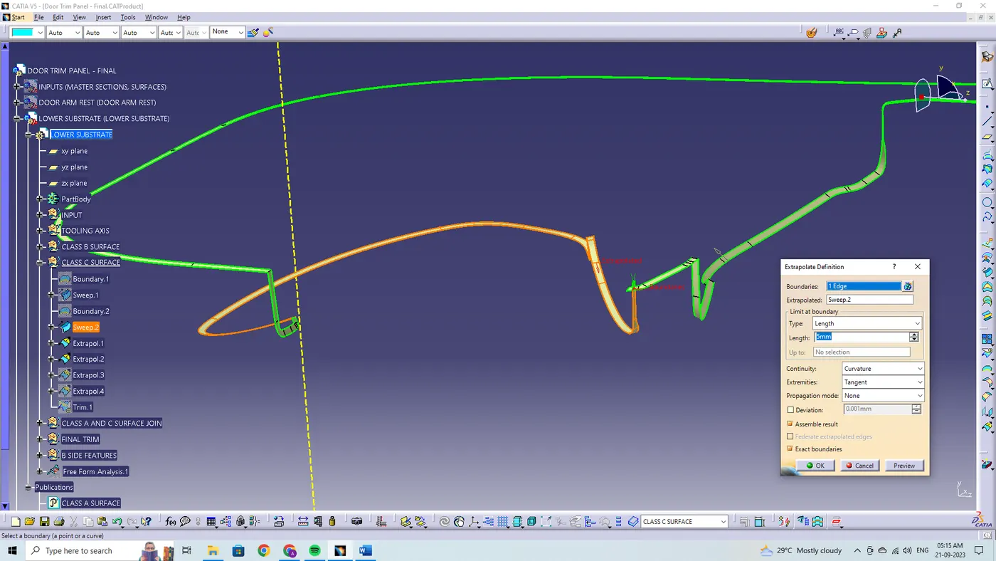
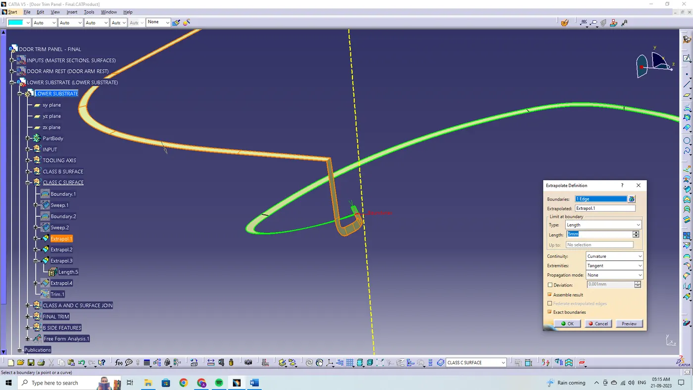
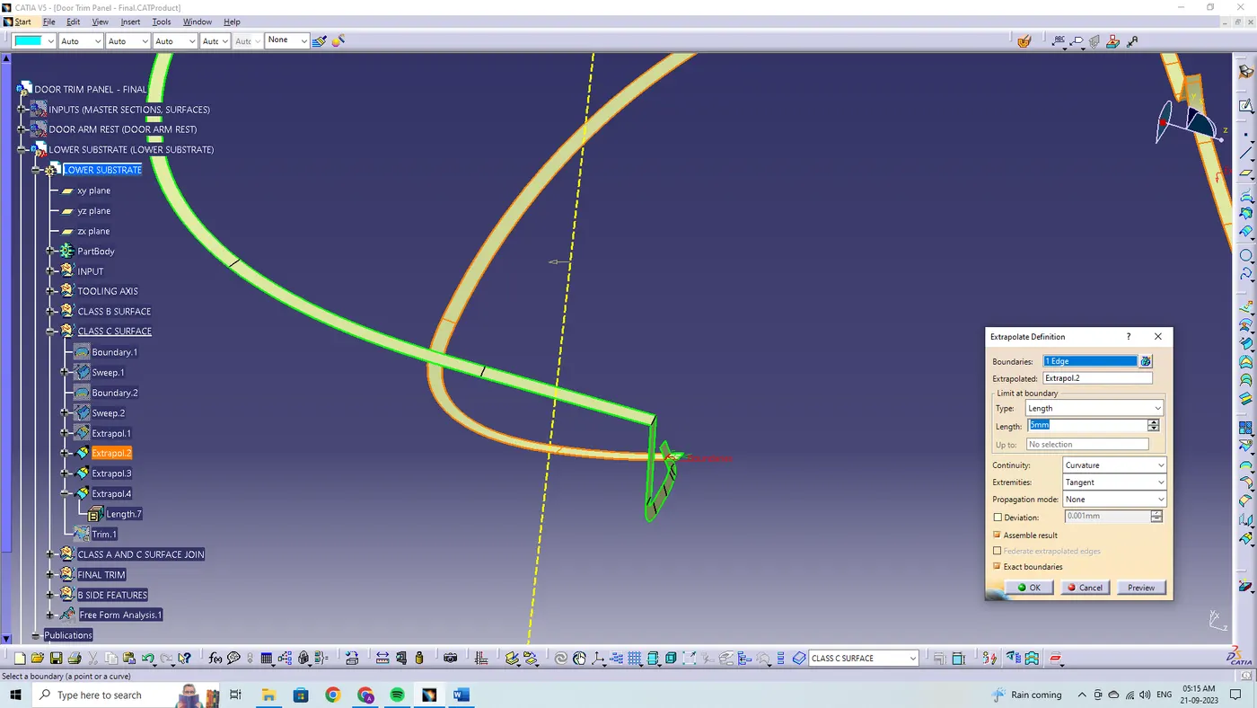
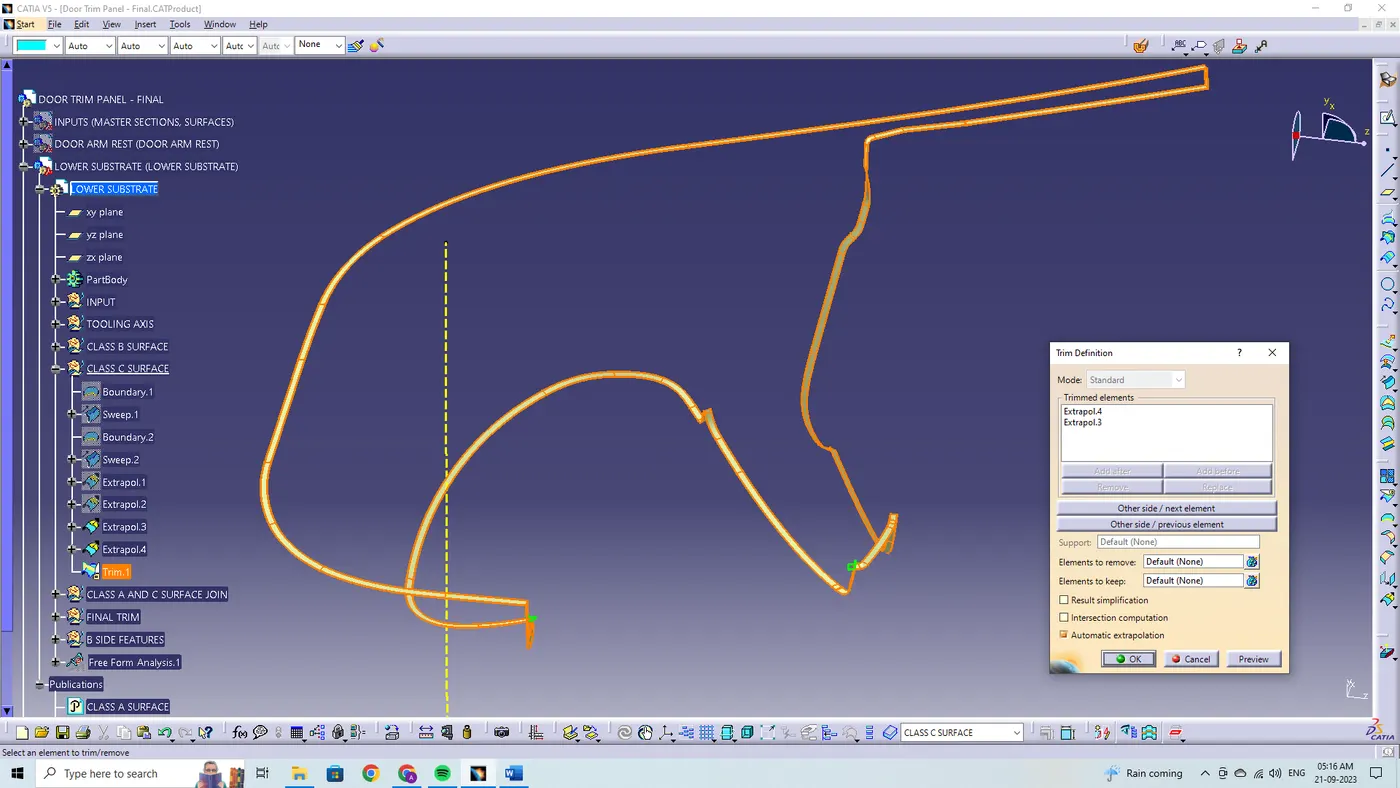
The class C surfaces are being created by using the sweep feature and the direction along the tooling direction and the reference with the surface and guide curve are being selected to form the class C surfaces.
JOINING THE CLASS A AND CLASS C SURFACES:
By using the join feature the class A and class C surface are joined together with the merging distance of 0.001 mm.
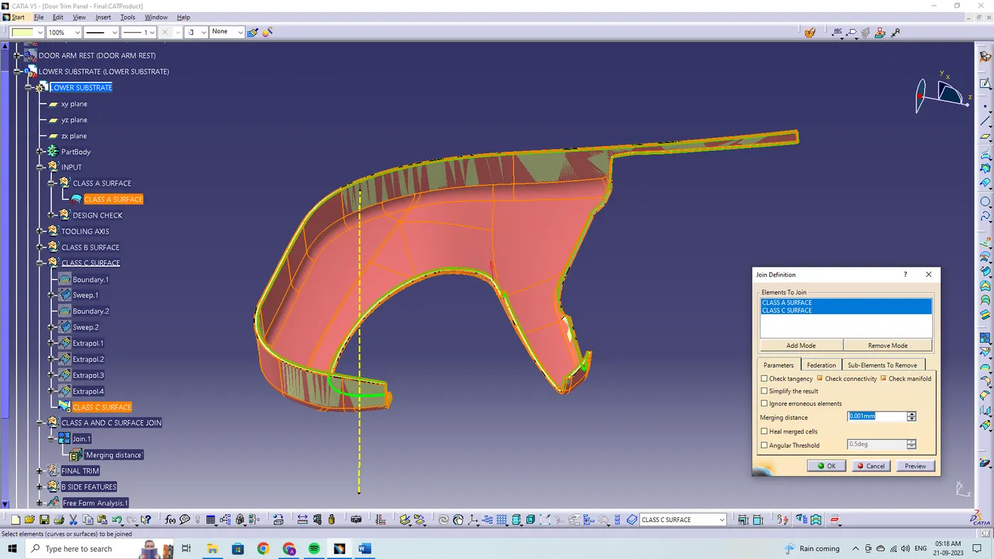
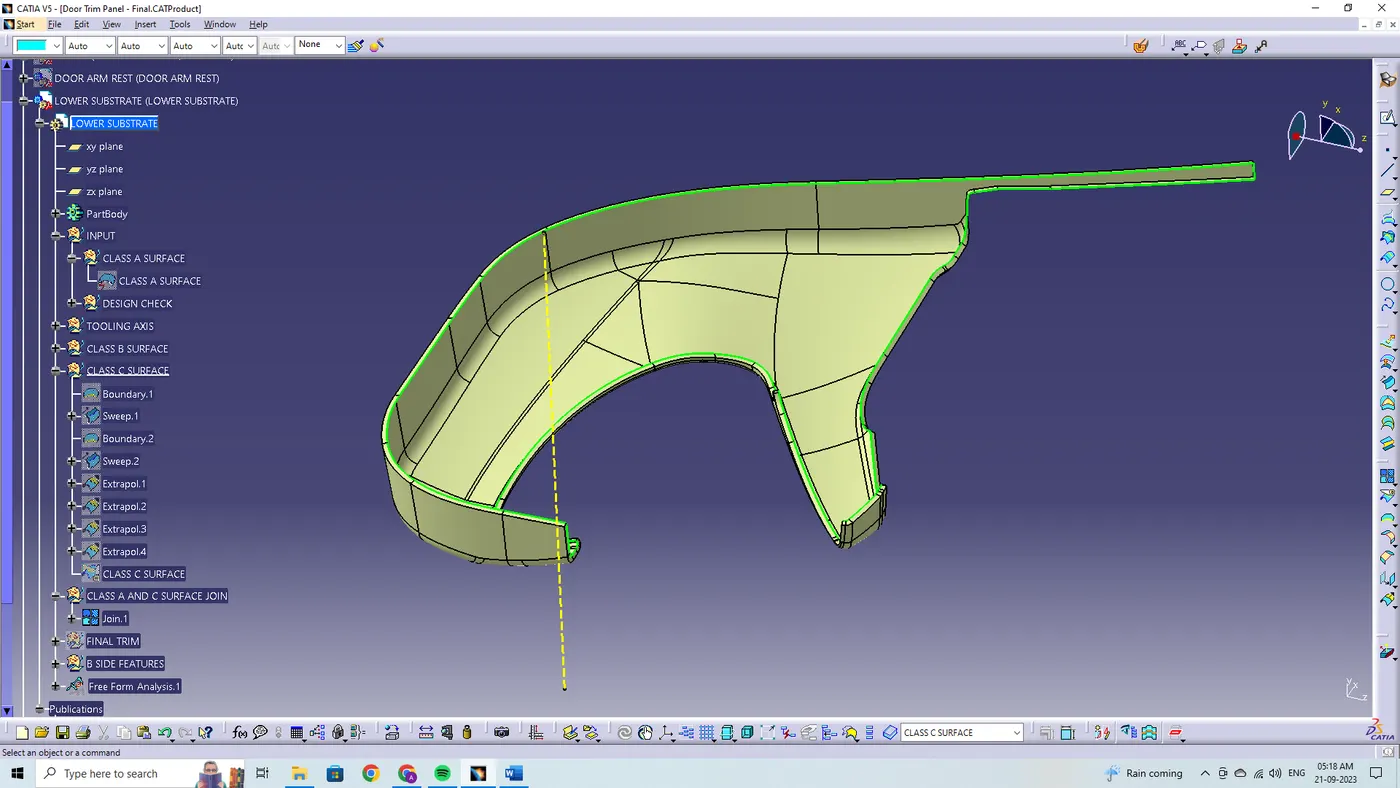
FINAL TRIMMING:
By using the intersection feature the first element and second element are being selected to check the intersection between the created class B and joined class (A+C).
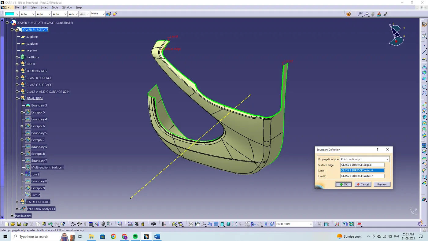
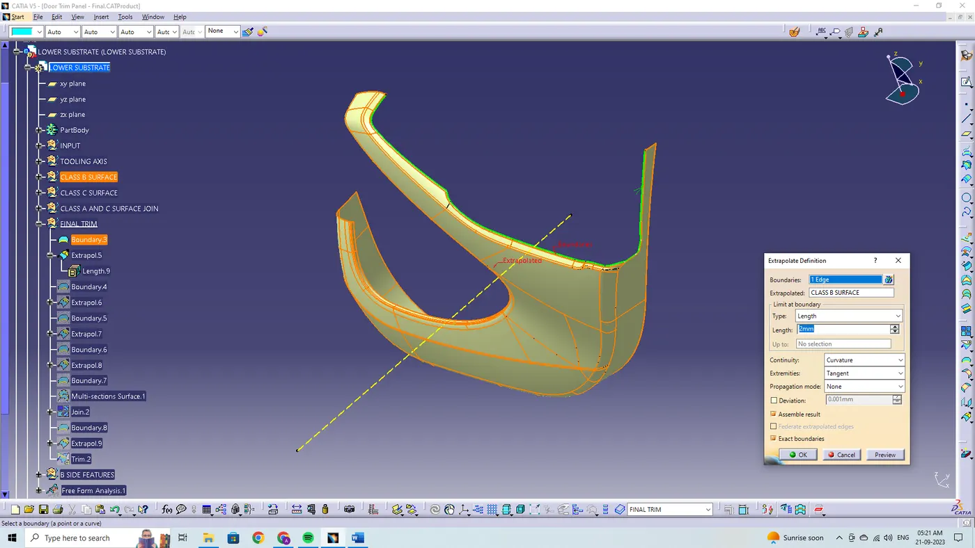
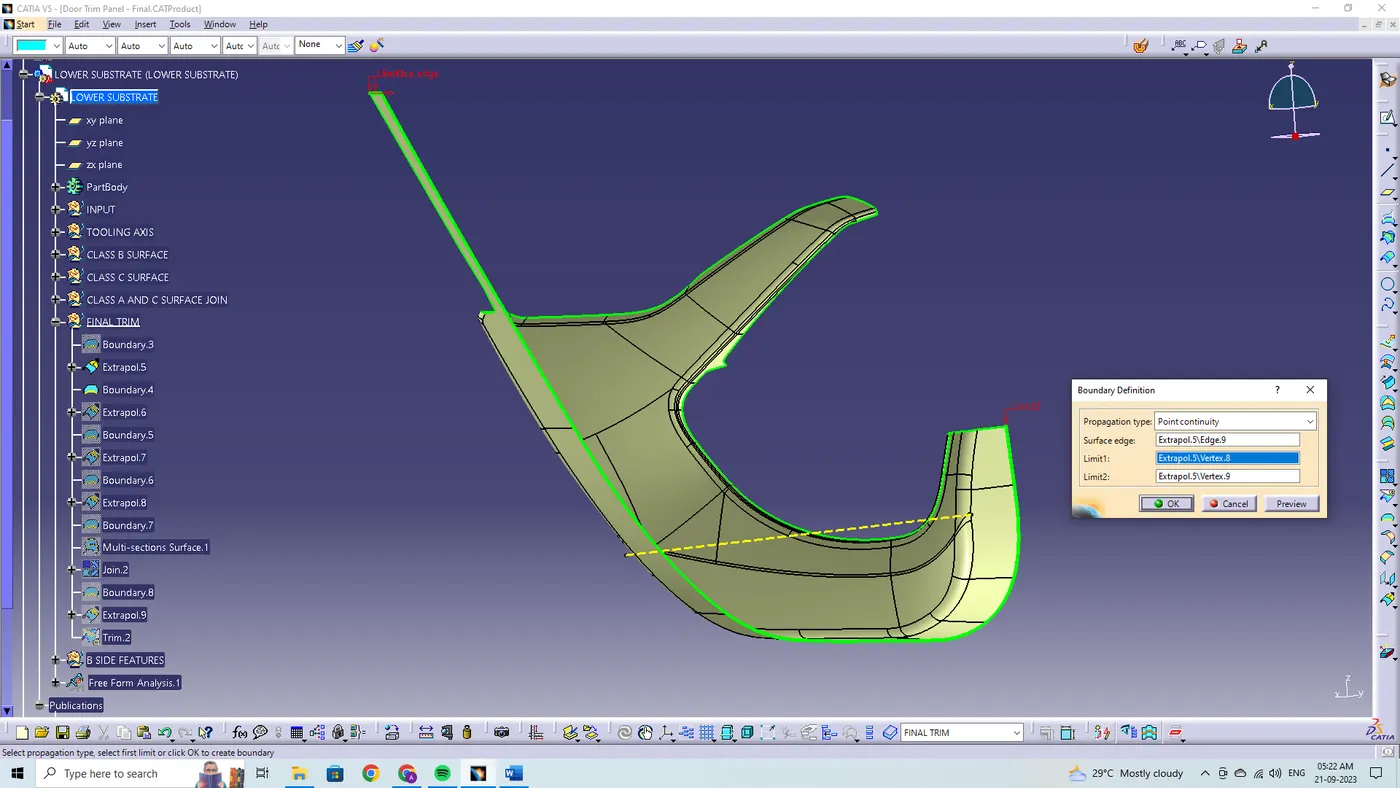
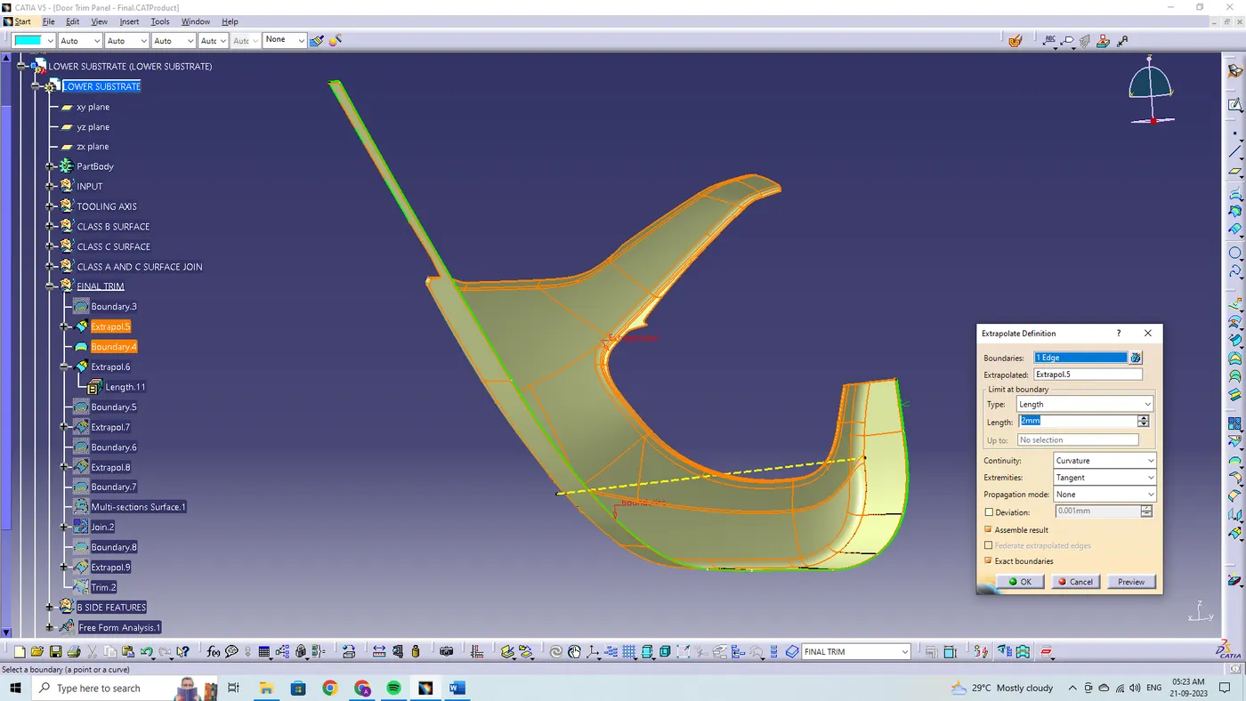
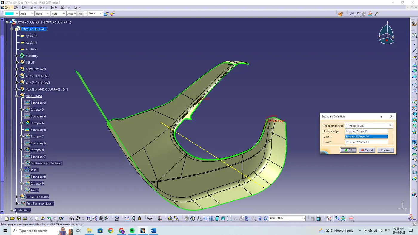
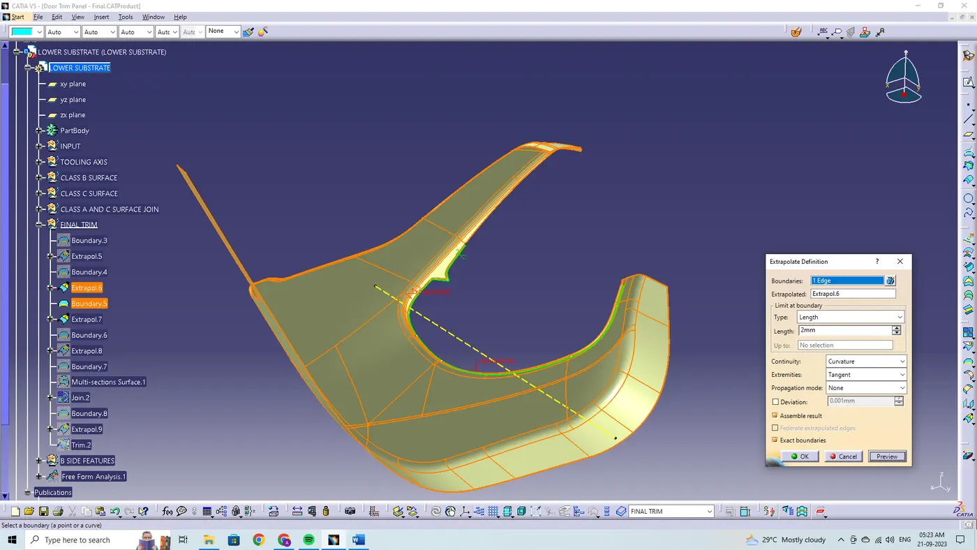
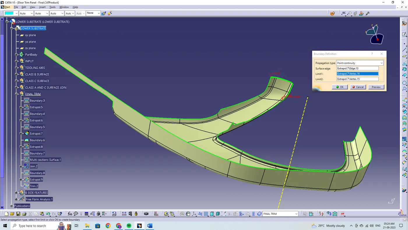
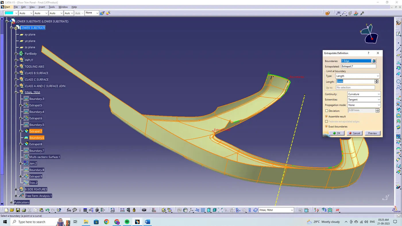
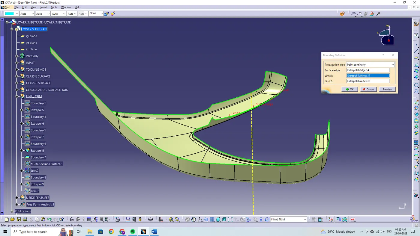
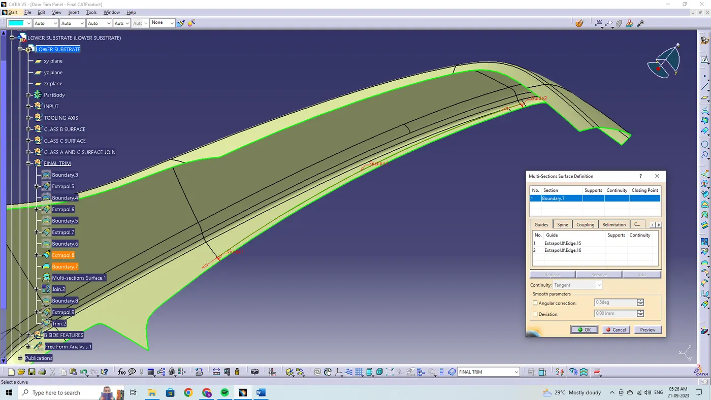
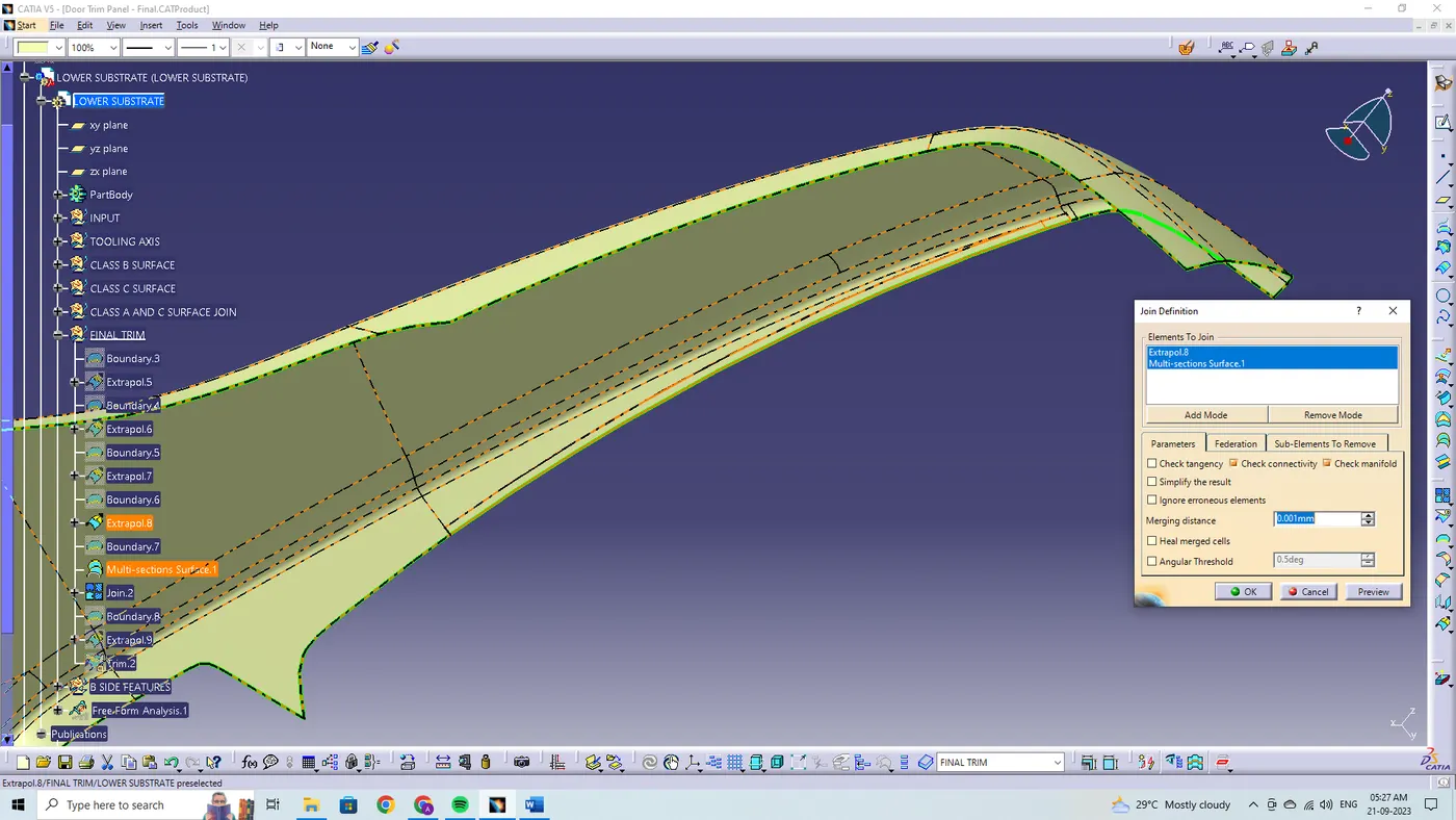
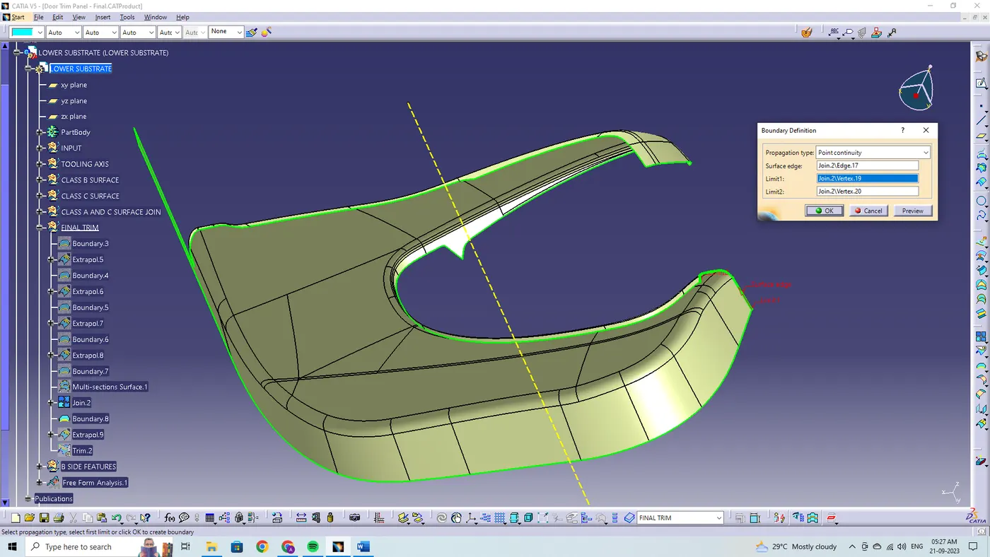
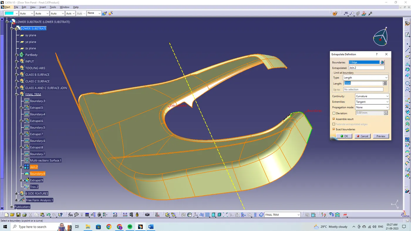
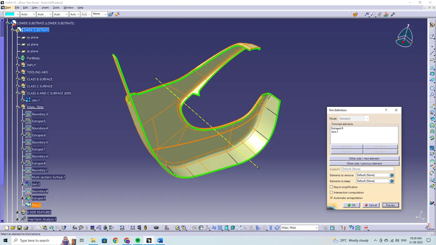
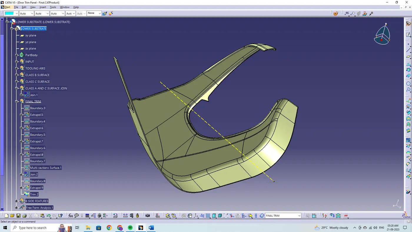
The final trimming has been performed on class B and joined class A and C surfaces. The trimming has been performed.
CLOSED SURFACE:
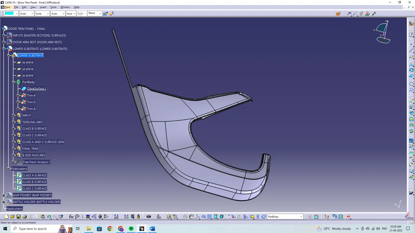
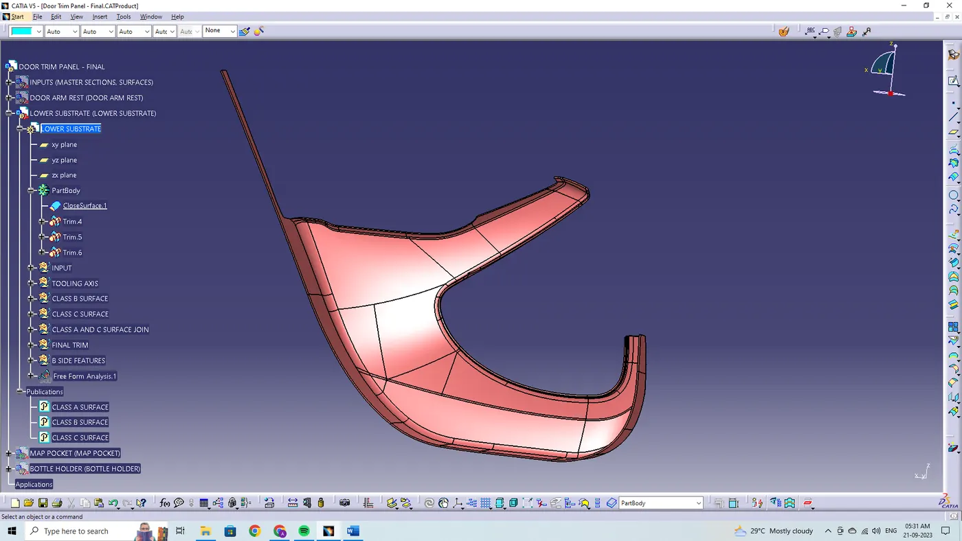
By using the close surface definition, the part surface is selected to make them into solid part from the part workbench.
DRAFT ANALYSIS:
The draft analysis has been performed on the final component created as a closed body using the part design closed surface feature. For plastic components the minimum angle required for the draft to be 3 degrees.
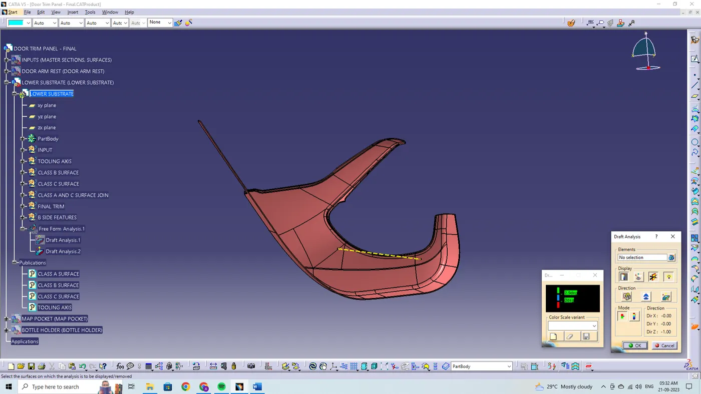
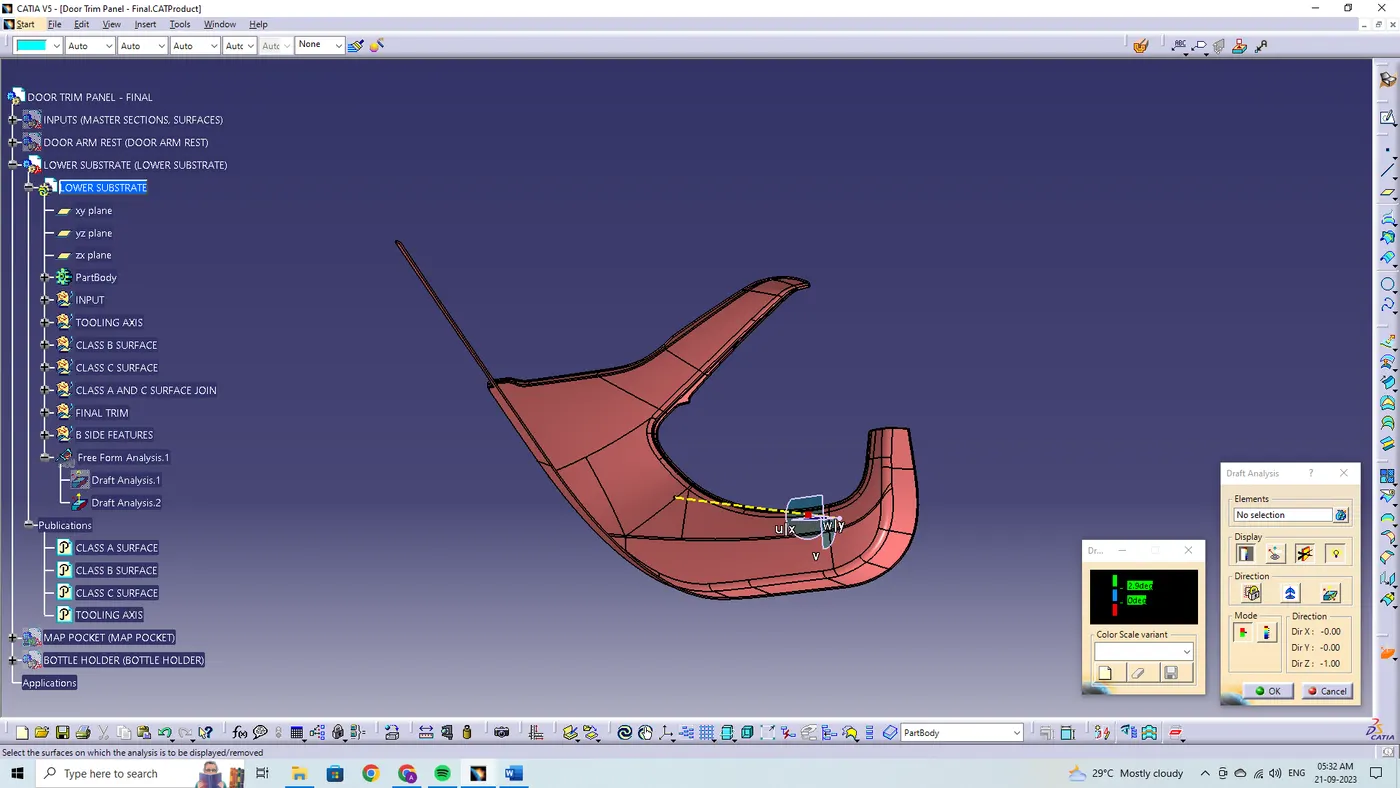
The direction compass is to be selected and placed it on the main tooling axis line and the compass are being locked using the lock feature in the directions.
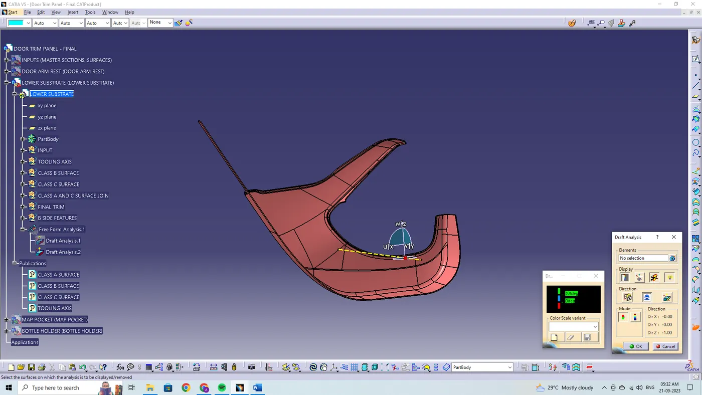
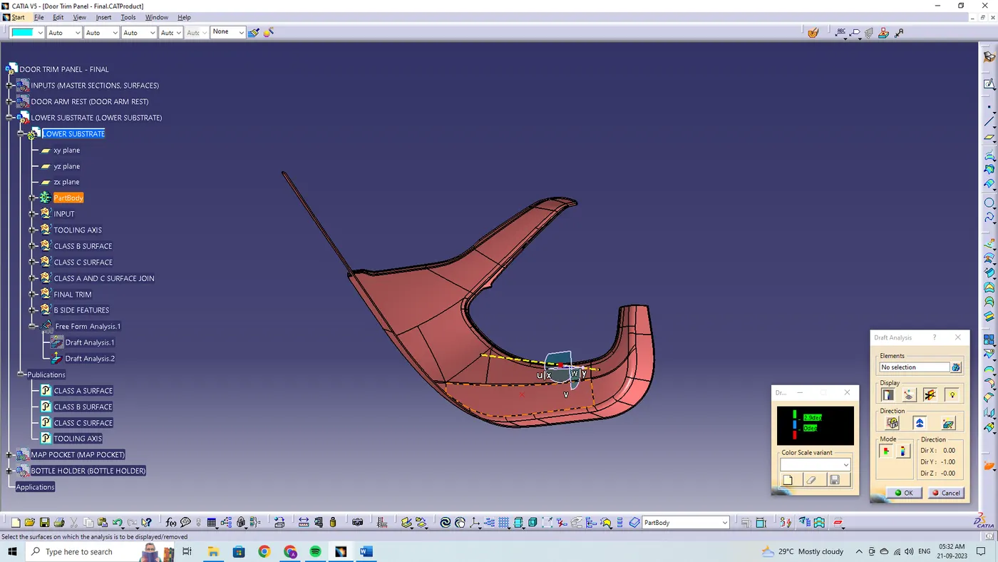
In the display window the colour code variants are being selected, to know the range of the draft in the class A surface. In the display window the colour variants show,
- For 3 degree - Green color variant (Positive)
- For 0 degree - Blue color variant
- For <0>
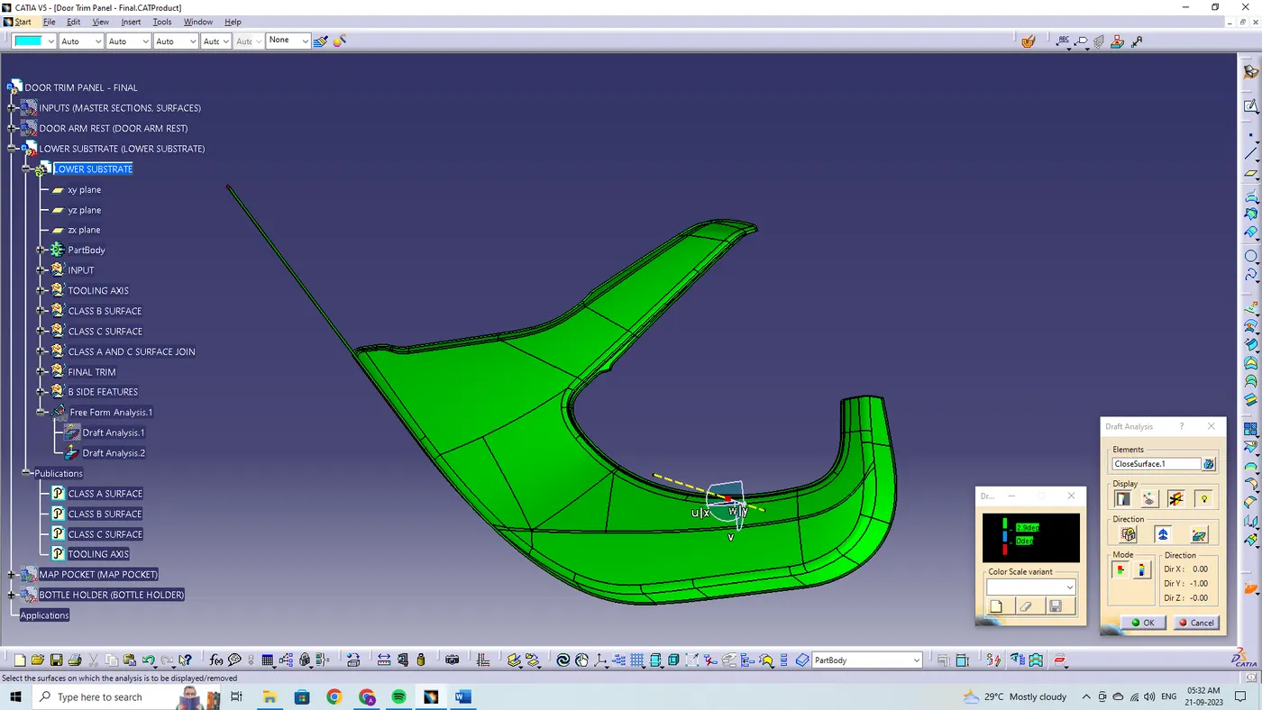
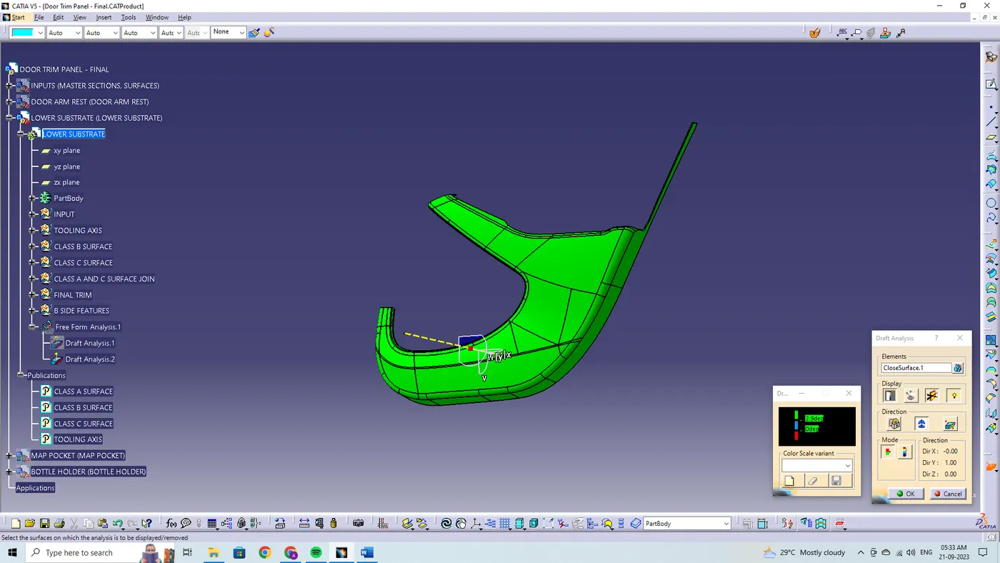
The draft analysis is being performed in both the core and cavity side of solid body. The green colour implies the draft angle are in the positive region. If the draft angle is being inverted the colour of the surface are implied as blue colour.
MAP POCKET:
CLASS A SURFACES:
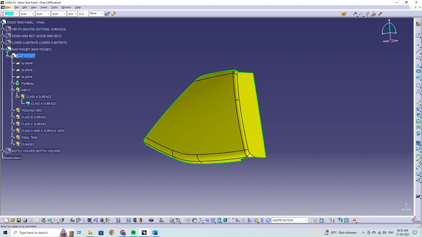
DESIGN CHECK:
The class A surface is checked visually by using the join feature or by using the boundary feature the class A surface is selected and disassembled the surface to check the surface are created without the gaps. The class A surface should be created without boundary gaps. By using the join definition with the merging distance of 0.001 mm the class A surface is joined together to check the connectivity.
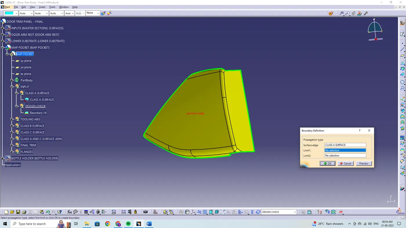
CREATING TOOLING AXIS:
The tooling for the class A surface is created in the direction in which the parts are ejected from the tool. The tooling axis which defines the core and cavity pulls apart from the tooling direction.
Along the x,y,z co-ordinate system the surfaces (Surfaces are likely to see visually) are selected.
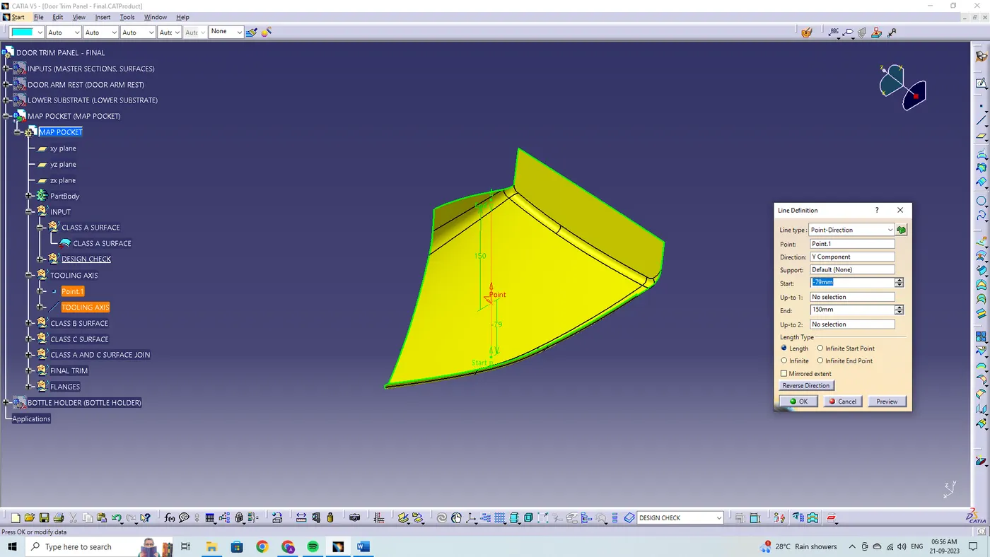
By using the point definition, the point has been created on surface midpoint along Y- direction.
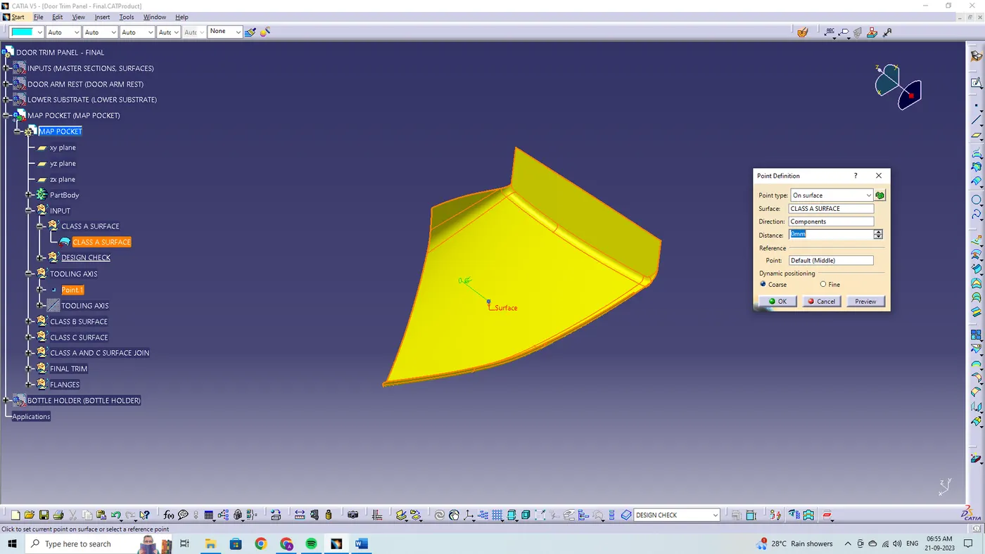
The main tooling axis has been created using the line definition feature. From the line type point direction, point has been selected and direction along Y component are selected to define the line.
DRAFT ANAYSIS:
For a class A surface, the draft analysis is to be performed to meet the requirement of the draft angle to the required tooling axis. For plastic components the minimum angle required for the draft to be 3 degrees.
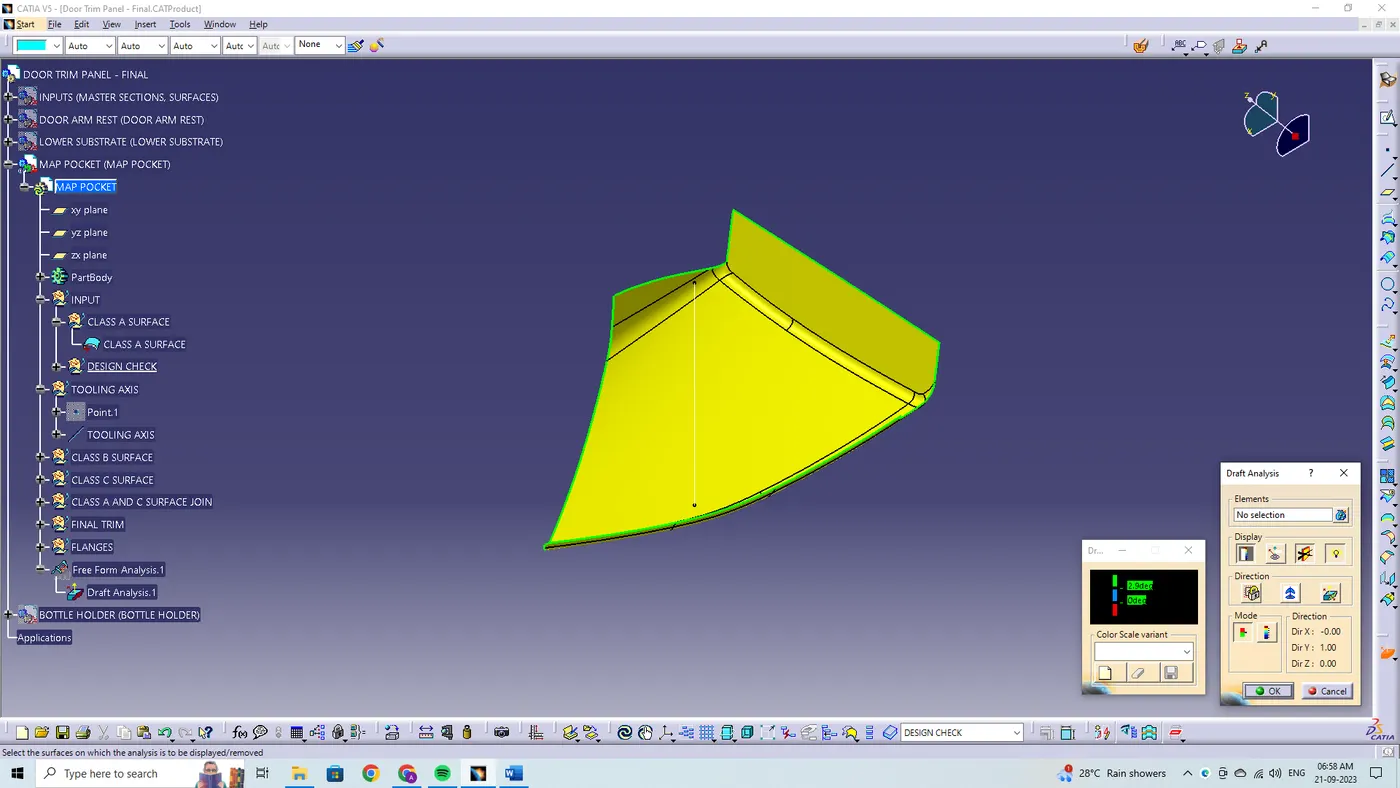
The direction compass is to be selected and placed on the main tooling axis line and the compass is being locked using the lock feature in the direction.
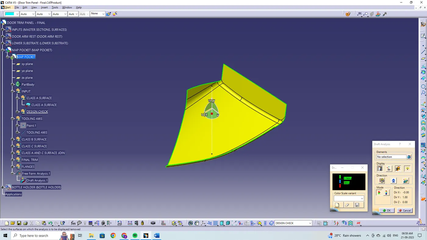
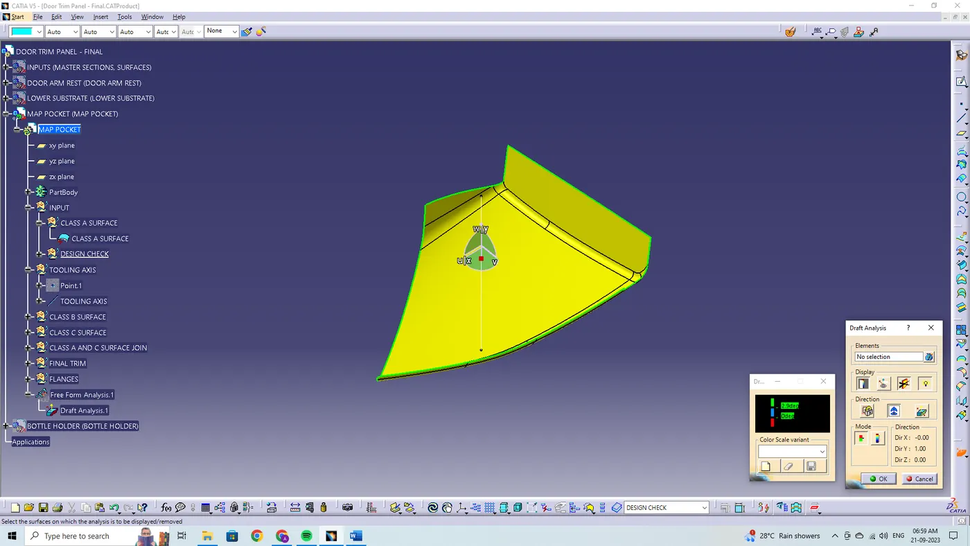
In the display window the colour code variants are being selected, to know the range of the draft in the class A surface. In the display window the colour variants show,
- For 3 degree - Green color variant (Positive)
- For 0 degree - Blue color variant
- For <0>
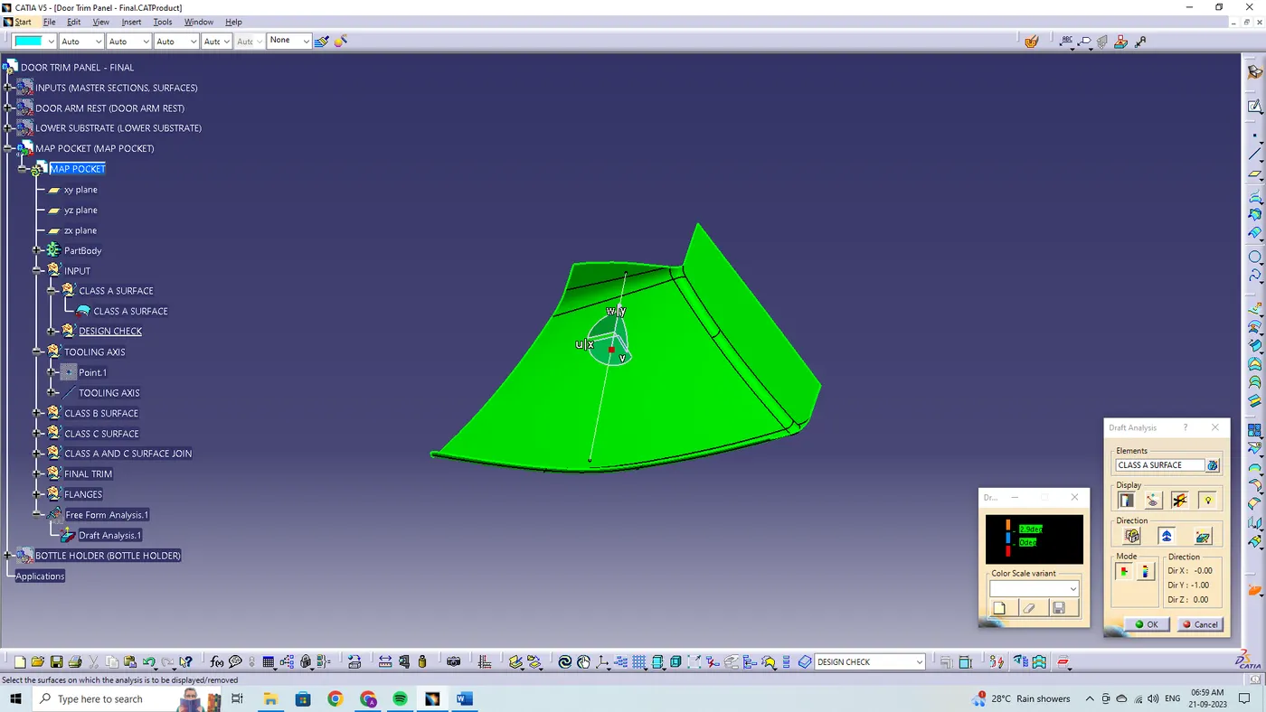
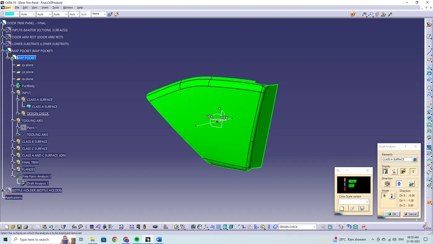
The draft analysis is being performed in both the core and cavity side of solid body. The green colour implies the draft angle are in the positive region. If the draft angle is being inverted the colour of the surface are implied as blue colour.
CREATION OF CLASS 'B' SURFACE:
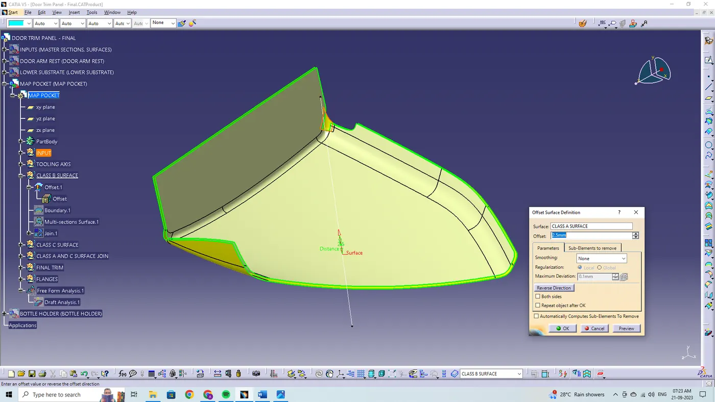
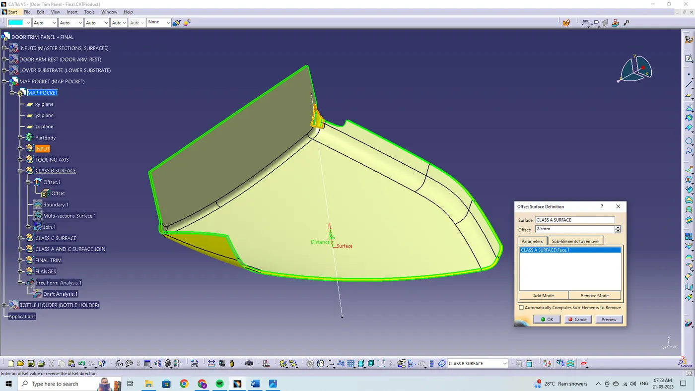
By using the class A surface, the class B surface is created by offsetting to the respective length to the respective direction. By using the offset surface definition the class A surface are been offset to the length of 2.5 mm to the respective direction.
CREATING CLASS 'C' SURFACE:
To make the class C surface, the boundaries are extracted from the class A surface. The outer boundary is being extracted using the boundary feature/extract definitions.
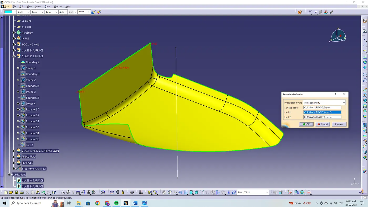
By using the sweep surface creation definition, the respective profile types are being selected and subtype with reference surface are being selected. In that the guide curve are selected as the boundary in the class A surface, and reference surface are selected, and the class C surface are being created to the respective length.
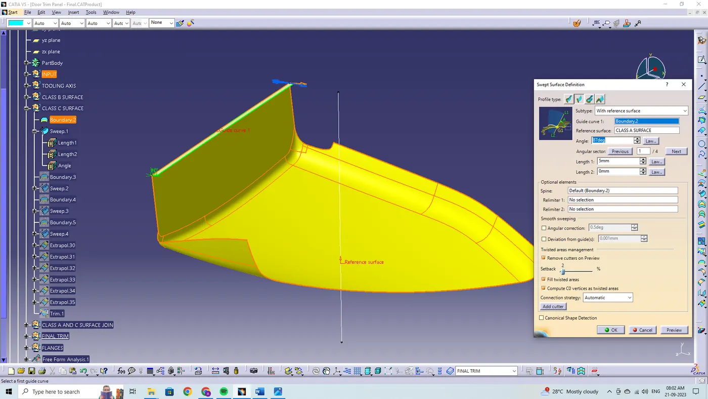
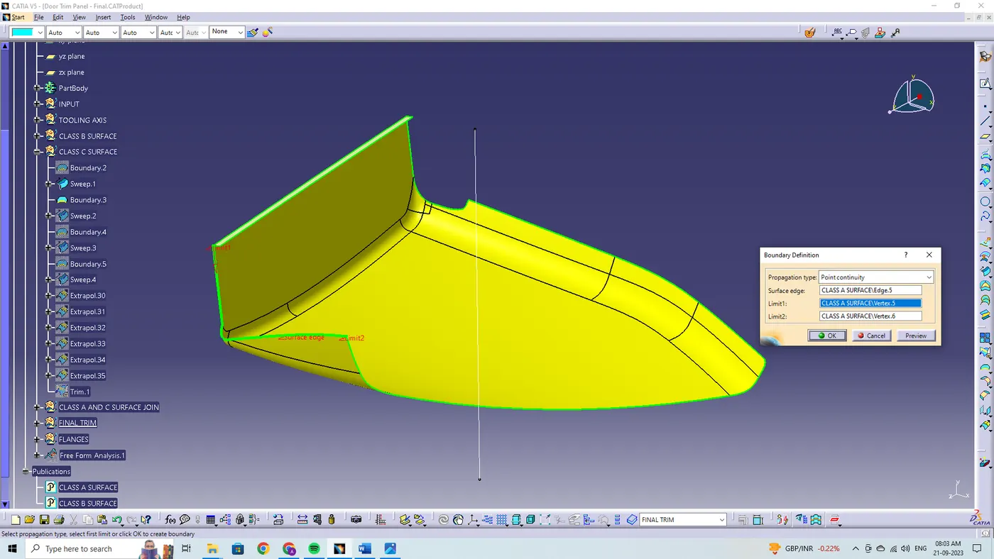
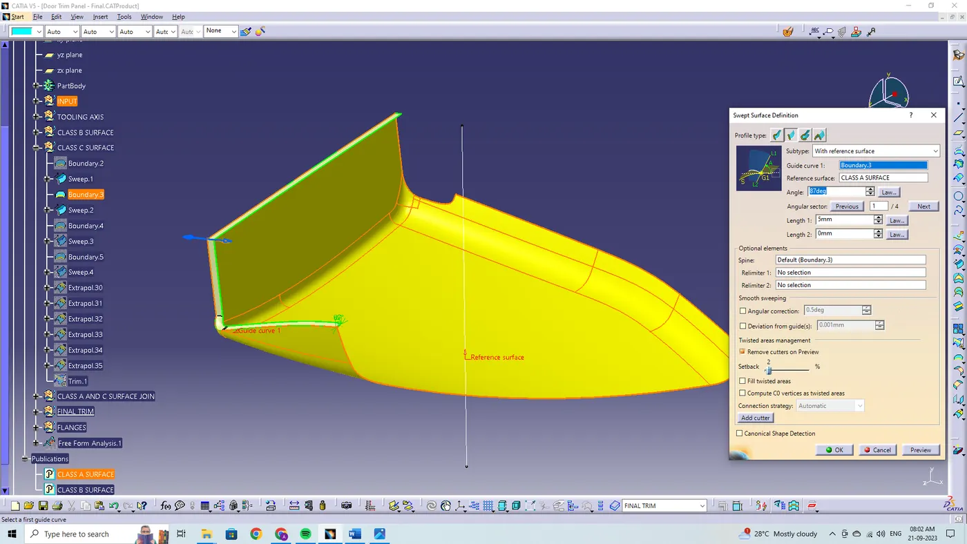
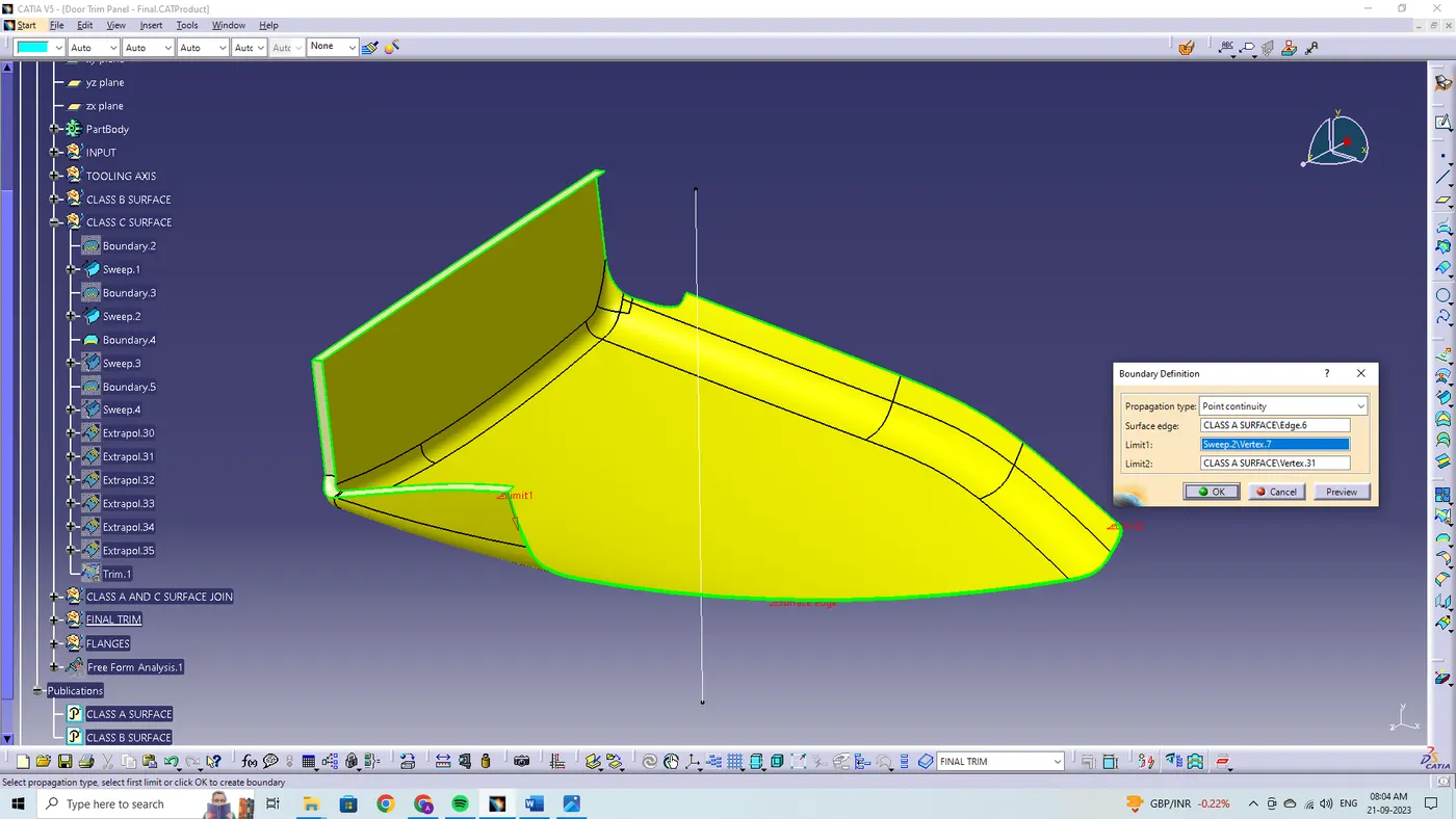
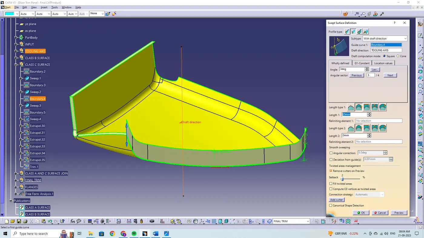
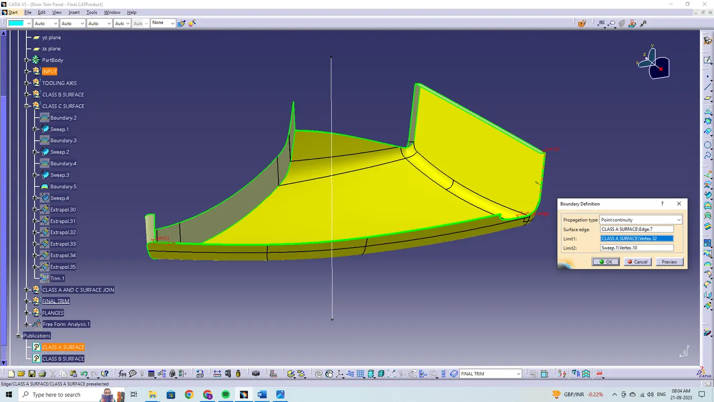
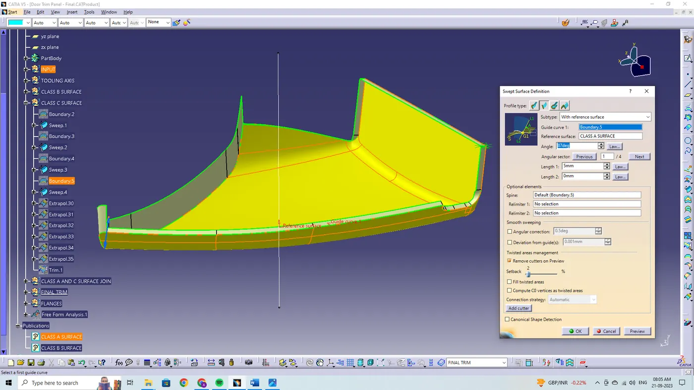
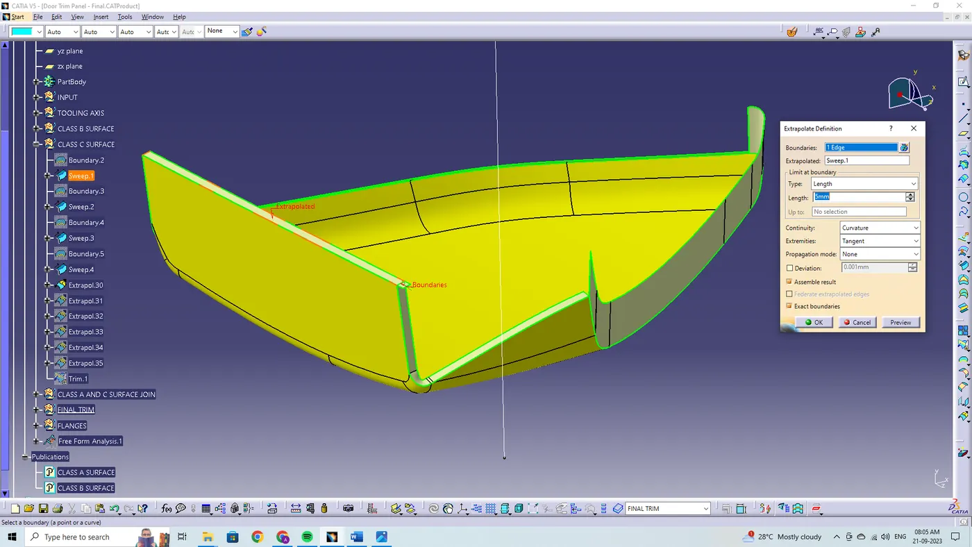
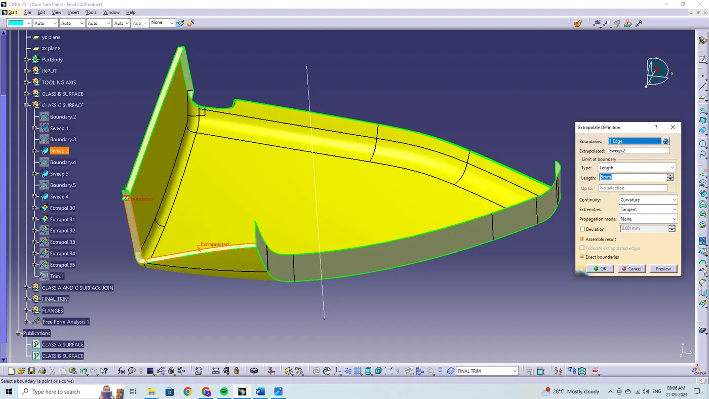
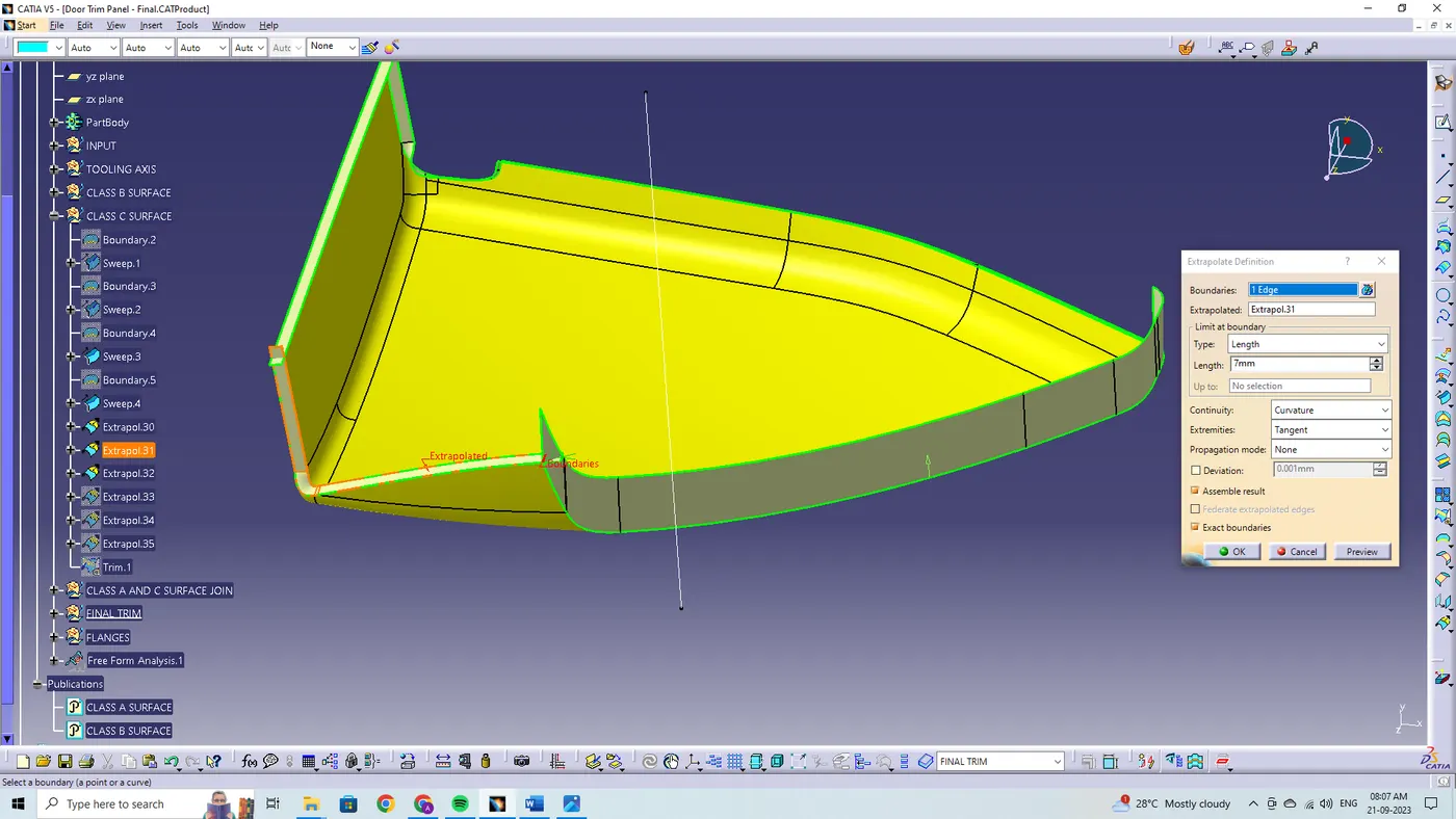
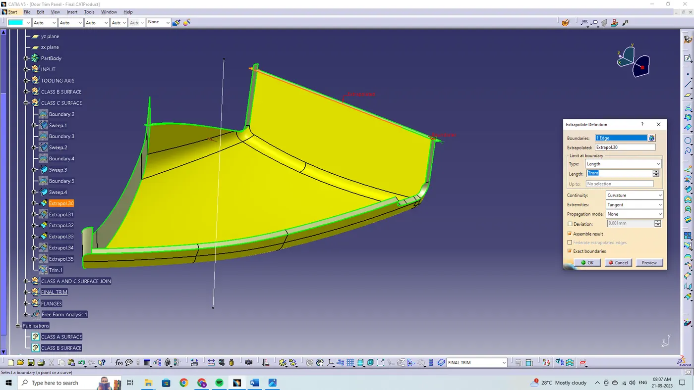
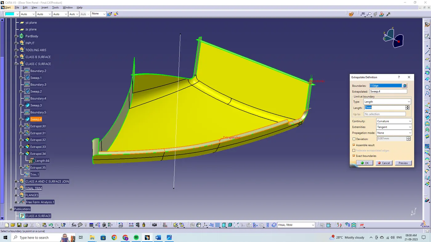
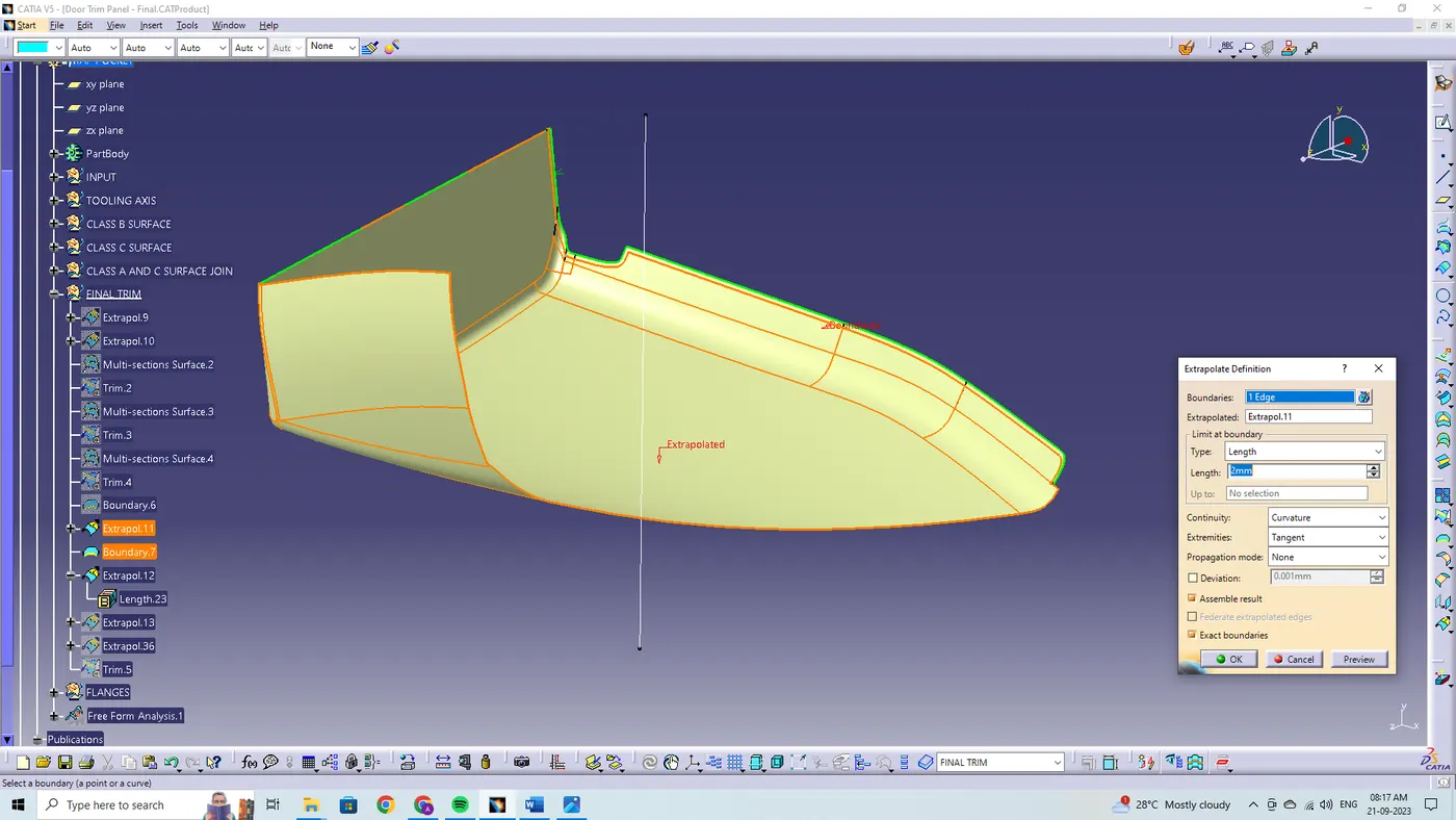
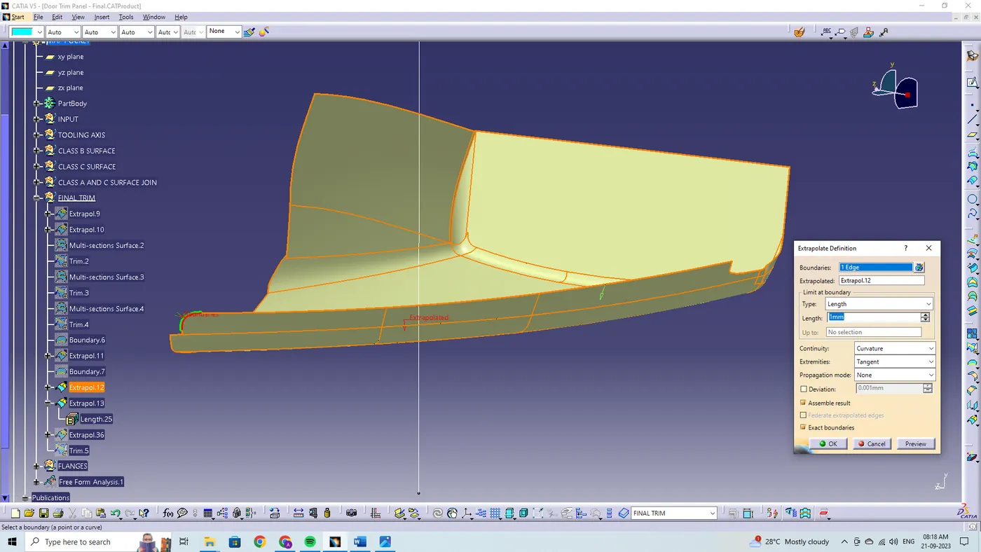
By using the extrapolation and trimming feature the edges are being extrapolated and trimmed together to form the class C surfaces.
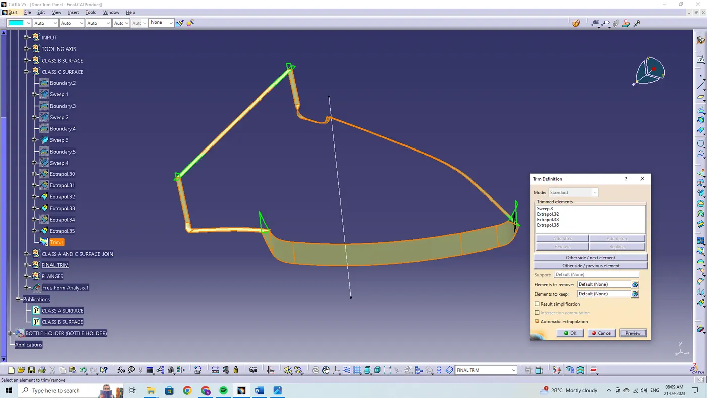
The class C surfaces are being created by using the sweep feature and the direction along the tooling direction and the reference with the surface and guide curve are being selected to form the class C surfaces.
JOINING THE CLASS A AND CLASS C SURFACES:
By using the join feature the class A and class C surface are joined together with the merging distance of 0.001 mm.
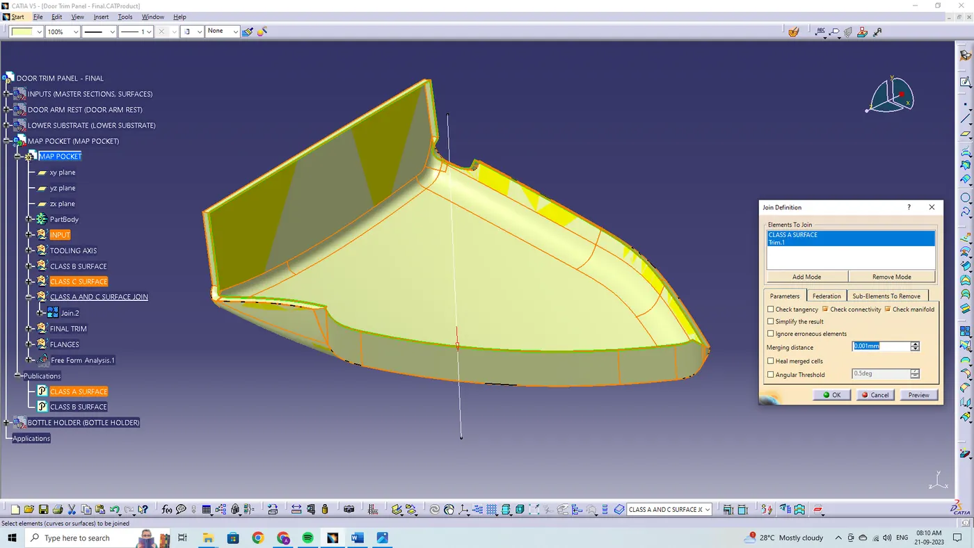
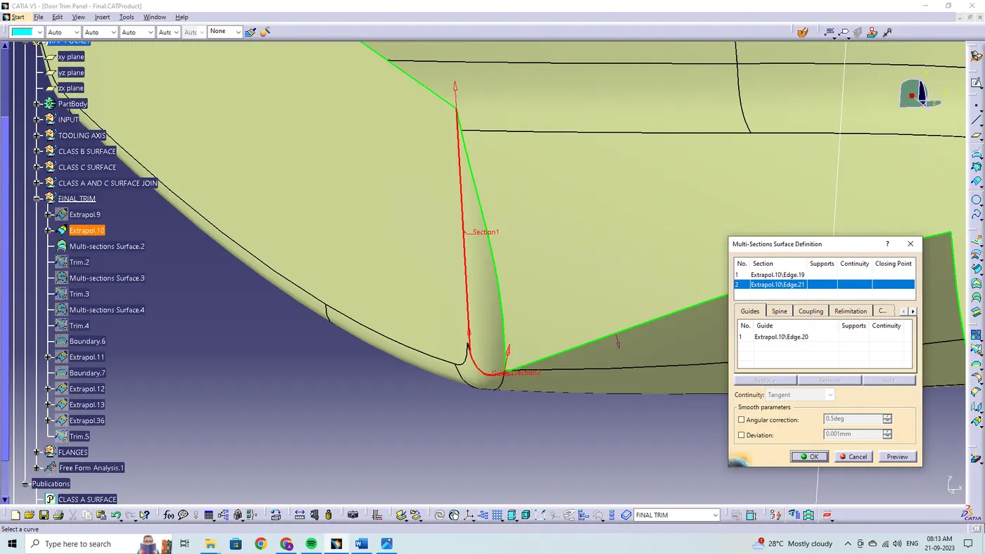
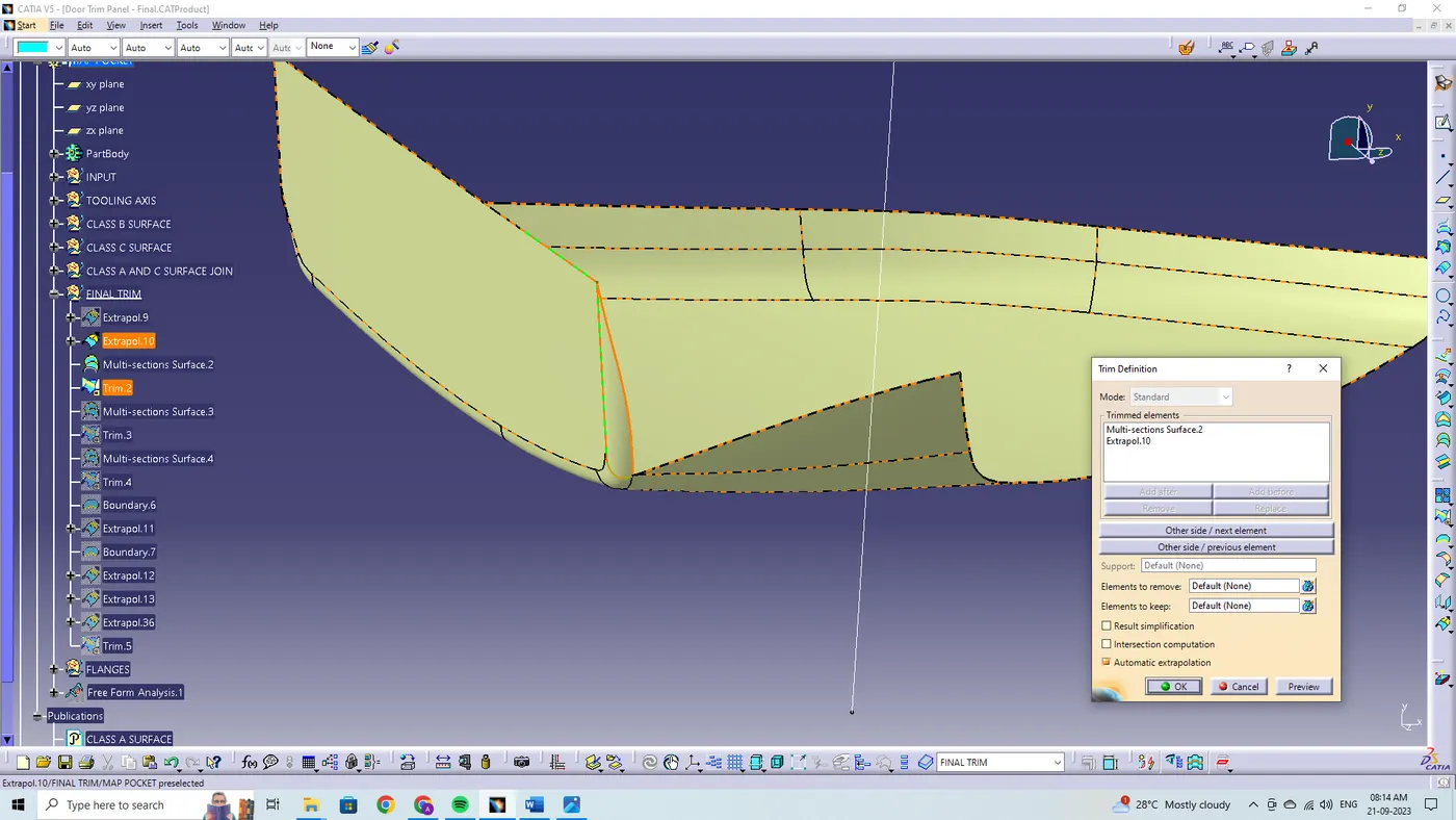
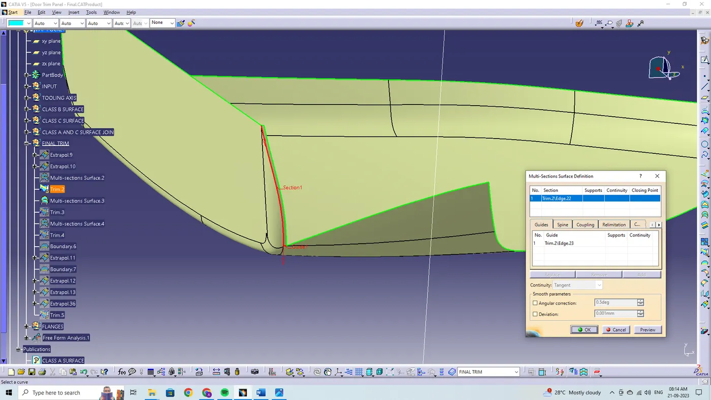
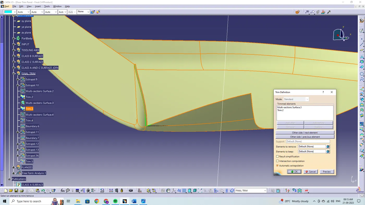
FINAL TRIMMING:
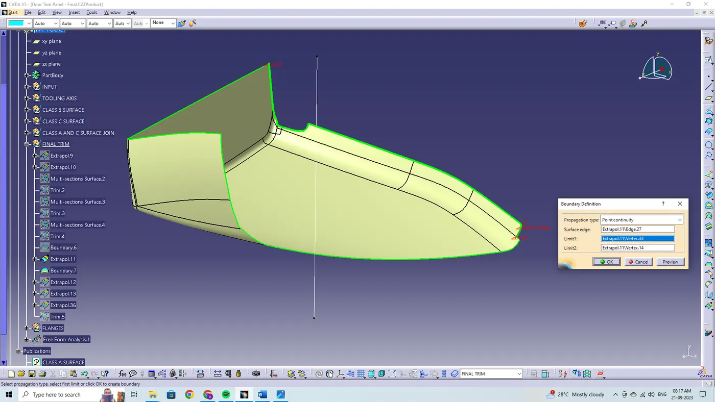
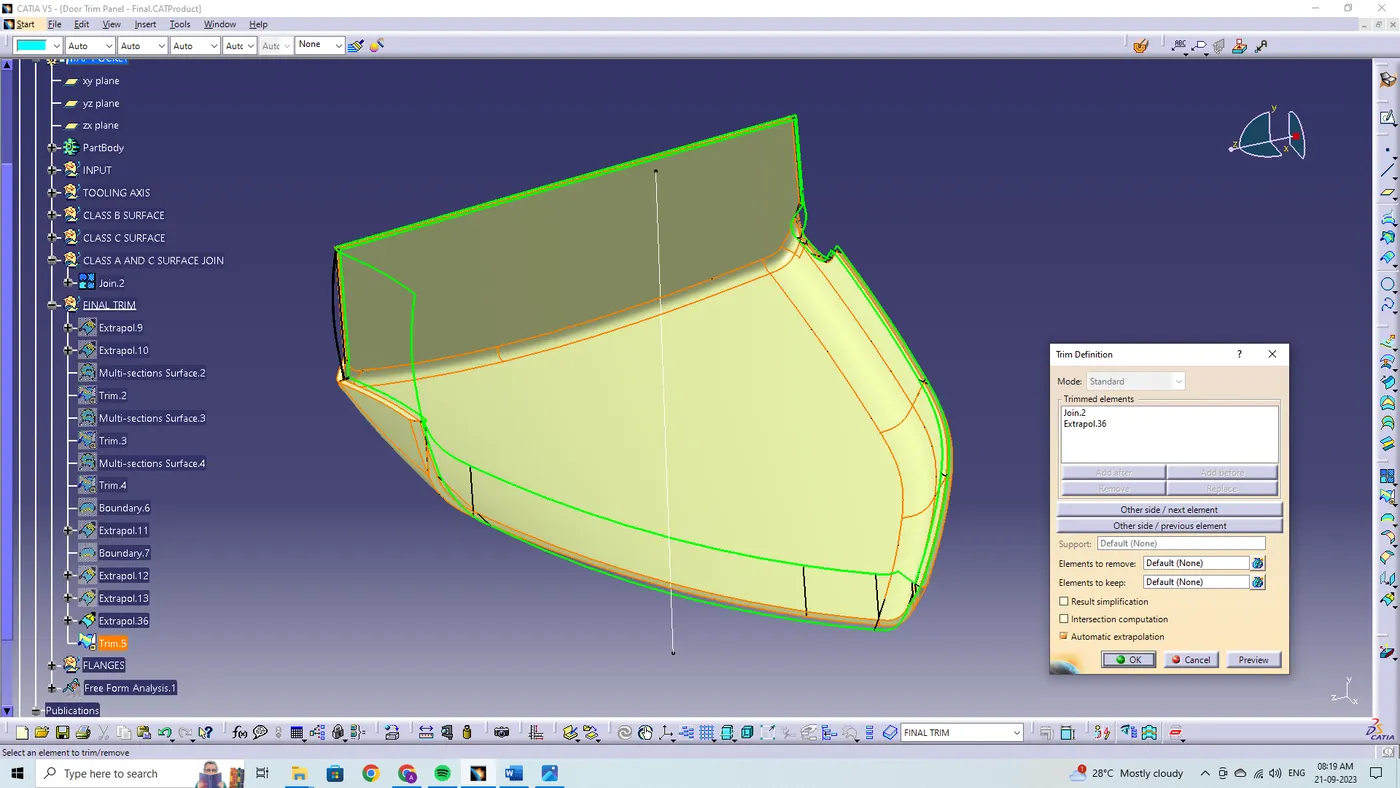
By using the intersection feature the first element and second element are being selected to check the intersection between the created class B and joined class (A+C).
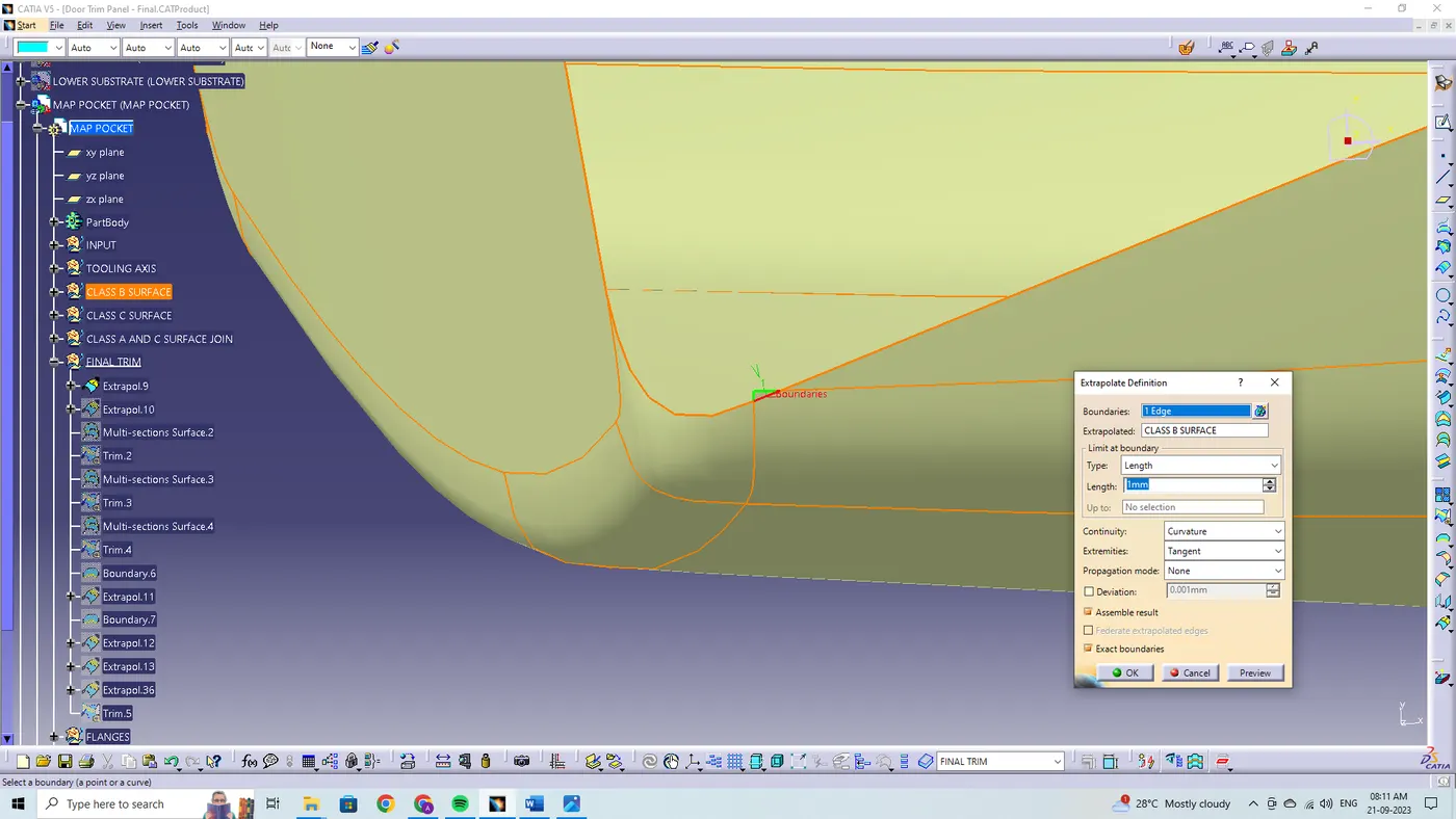
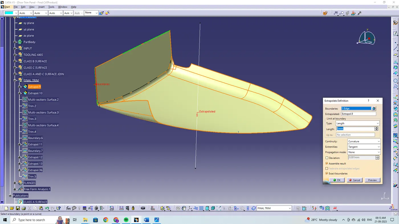
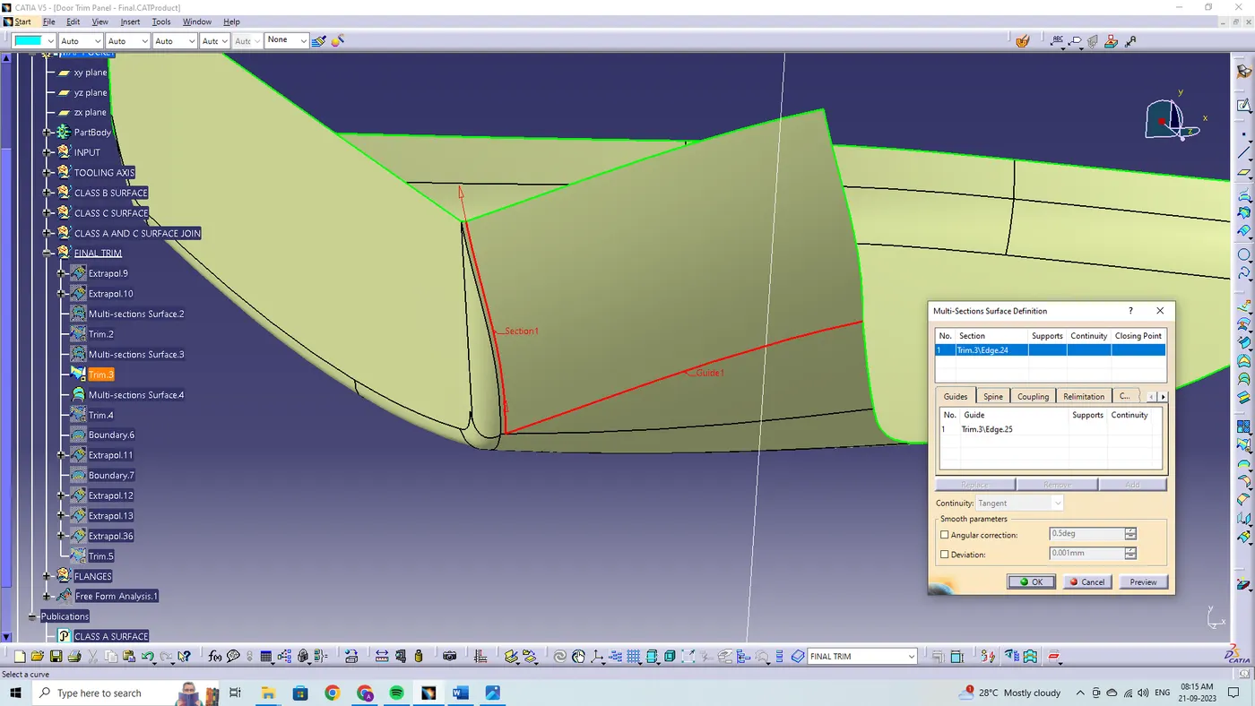
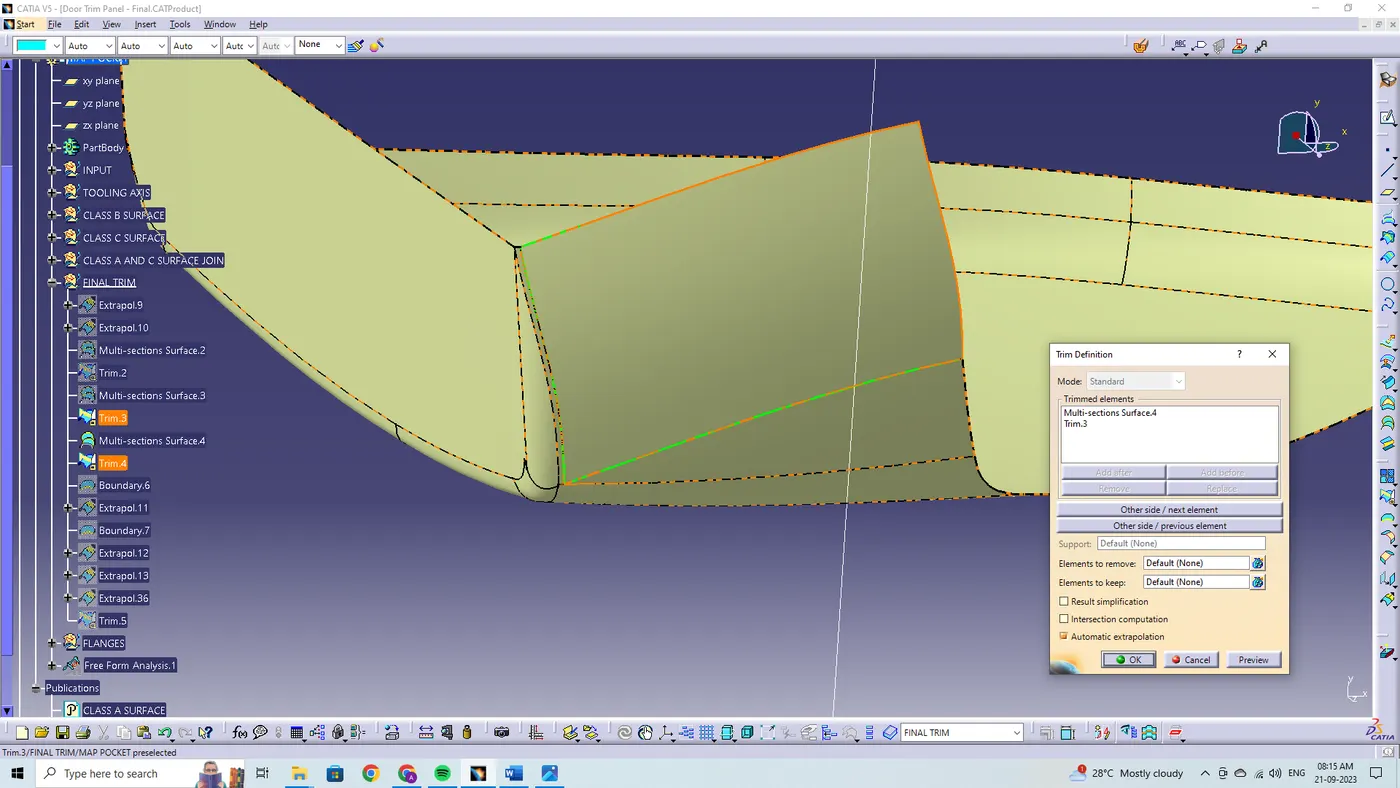
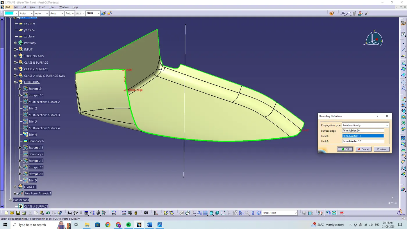
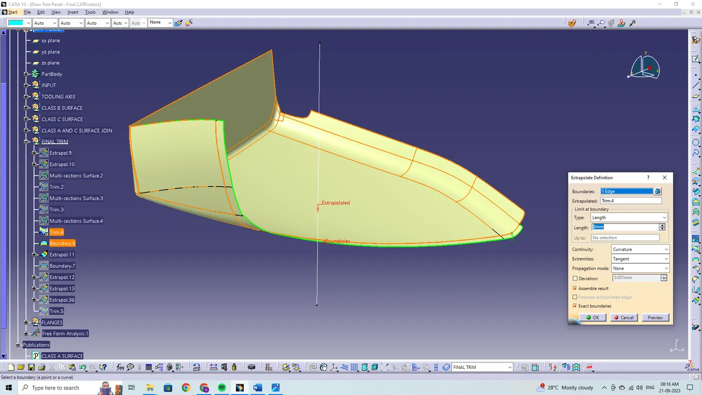

CLOSED SURFACE:
By using the close surface definition, the part surface is selected to make them into solid part from the part workbench.
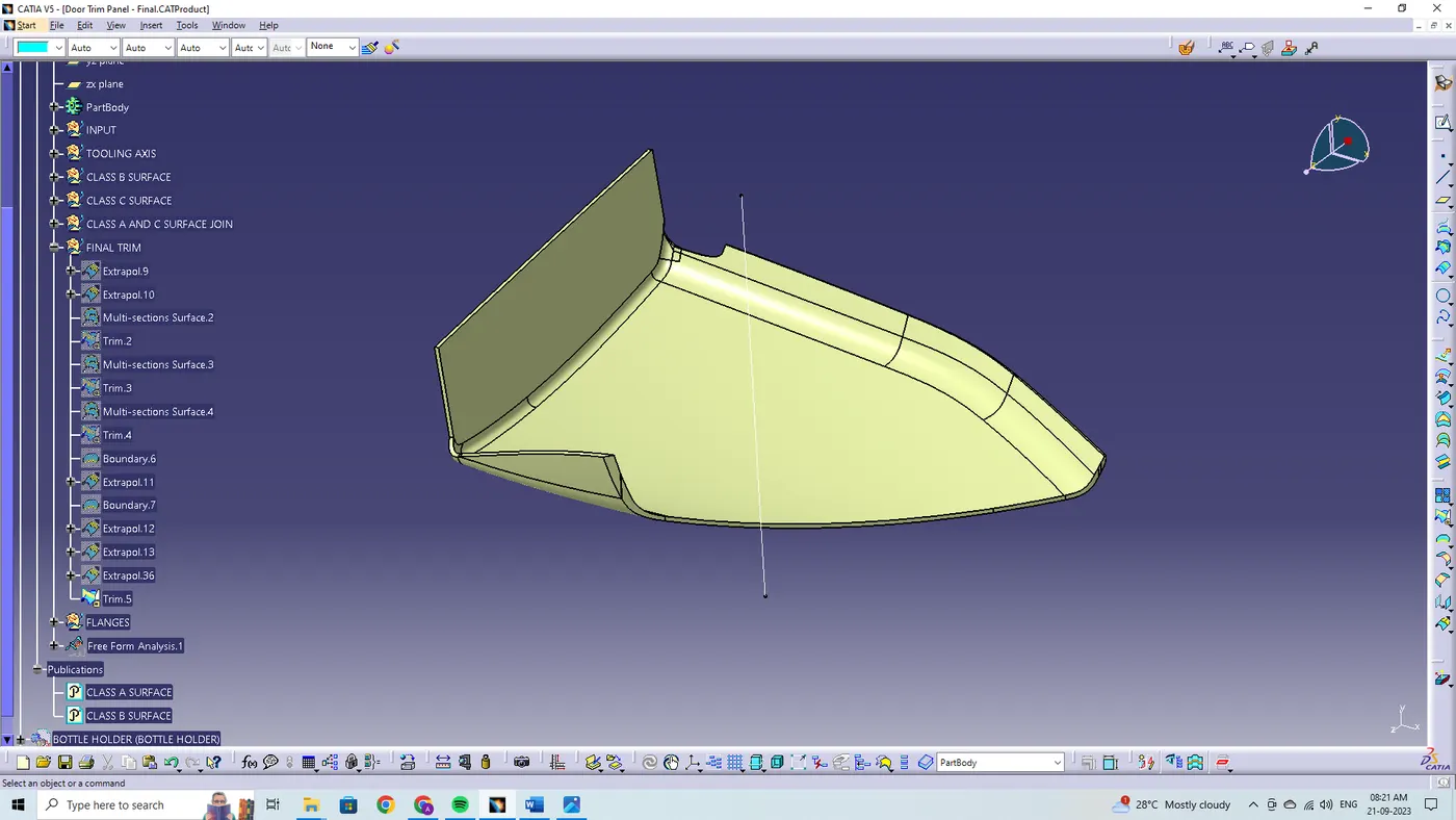
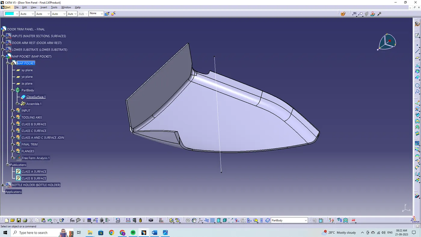
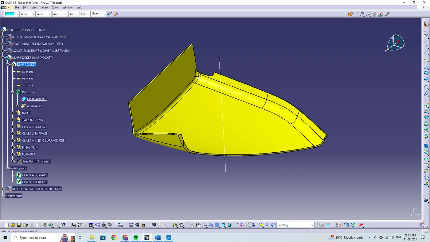
DRAFT ANALYSIS:
The draft analysis has been performed on the final component created as a closed body using the part design closed surface feature. For plastic components the minimum angle required for the draft to be 3 degrees.
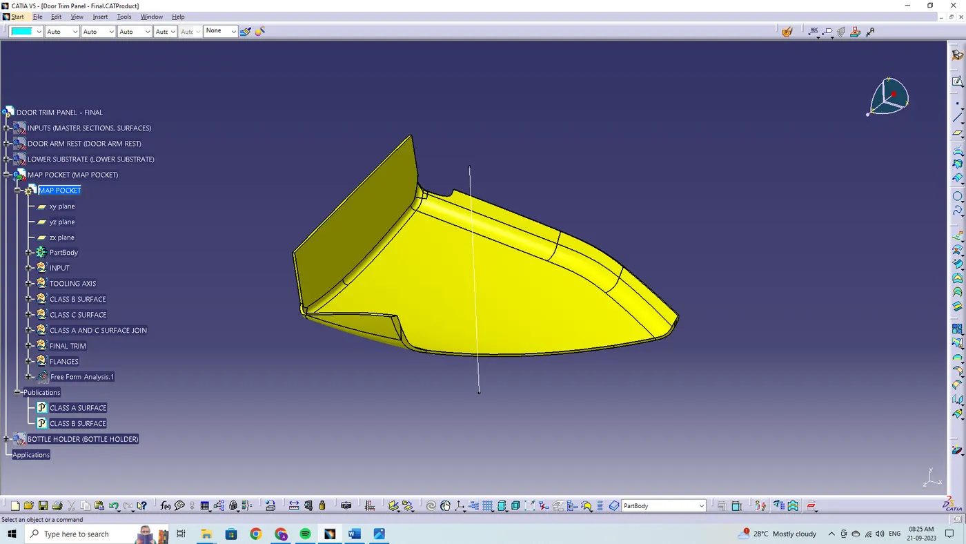
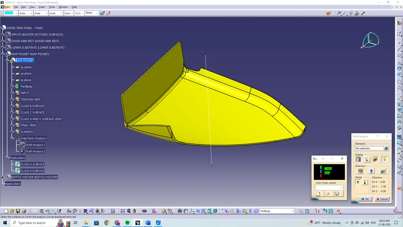
The direction compass is to be selected and placed it on the main tooling axis line and the compass is being locked using the lock feature in the directions.
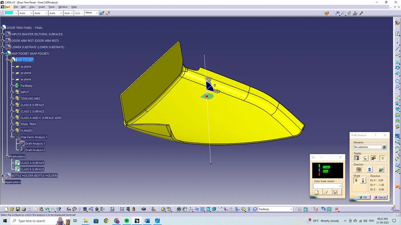
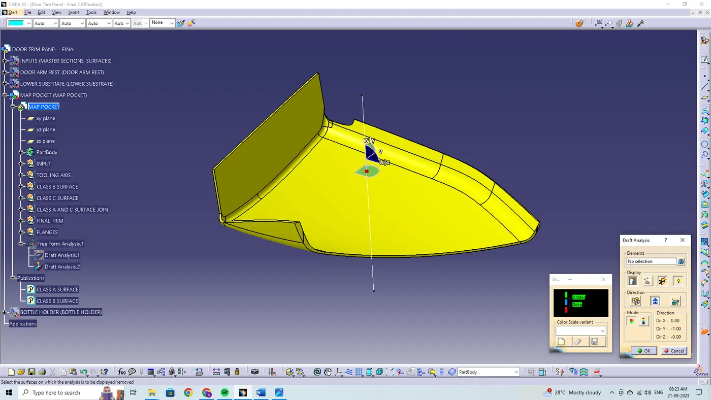
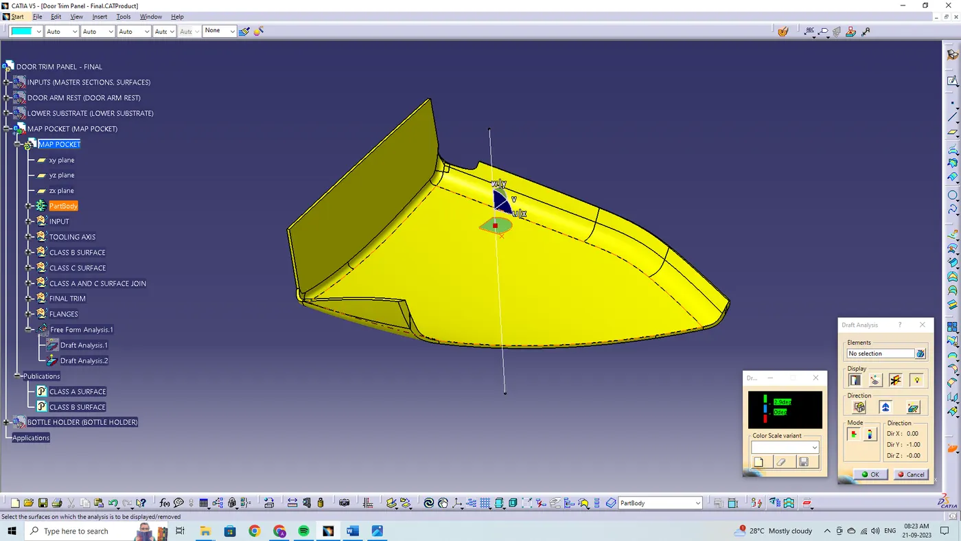
In the display window the colour code variants are being selected, to know the range of the draft in the class A surface. In the display window the colour variants show,
- For 3 degree - Green color variant (Positive)
- For 0 degree - Blue color variant
- For <0>
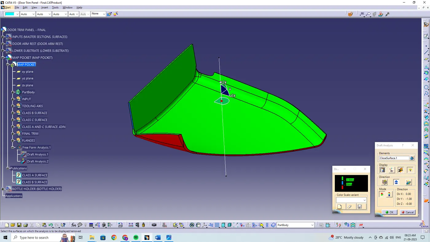
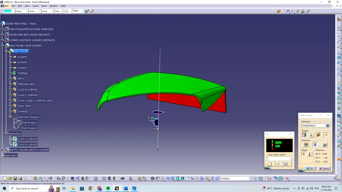
The draft analysis is being performed in both the core and cavity side of solid body. The green colour implies the draft angle are in the positive region. If the draft angle is being inverted the colour of the surface are implied as blue colour.
BOTTLE HOLDER:
CLASS A SURFACE:
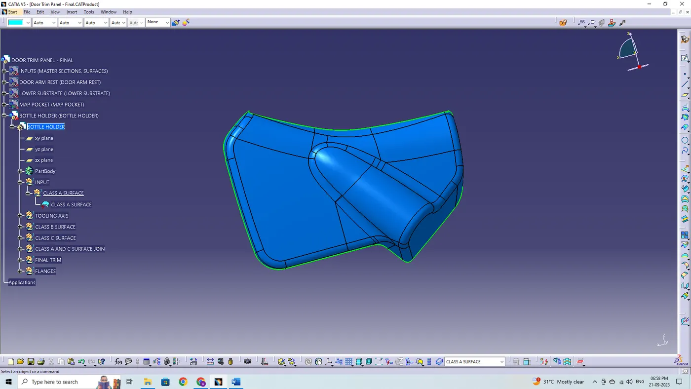
DESIGN CHECK:
The class A surface is checked visually by using the join feature or by using the boundary feature the class A surface is selected and disassembled the surface to check the surface are created without the gaps. The class A surface should be created without boundary gaps. By using the join definition with the merging distance of 0.001 mm the class A surface is joined together to check the connectivity.
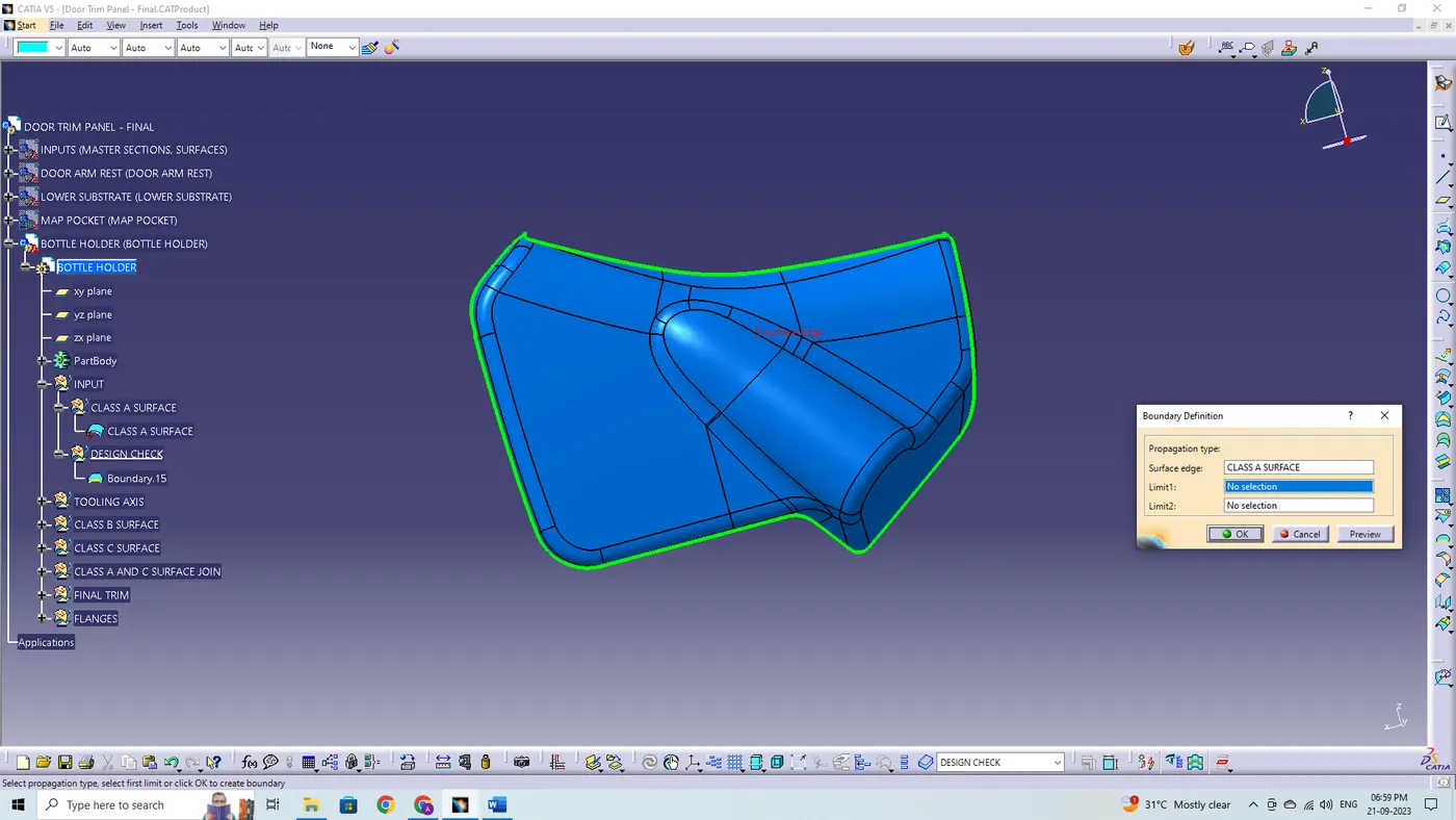
CREATING TOOLING AXIS:
The tooling for the class A surface is created in the direction in which the parts are ejected from the tool. The tooling axis which defines the core and cavity pulls apart from the tooling direction.
Along the x,y,z co-ordinate system the surfaces (Surfaces are likely to see visually) are selected.
By using the point definition, the point has been created on surface midpoint along Y- direction.
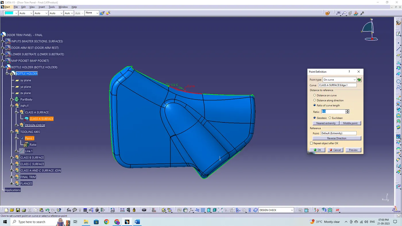
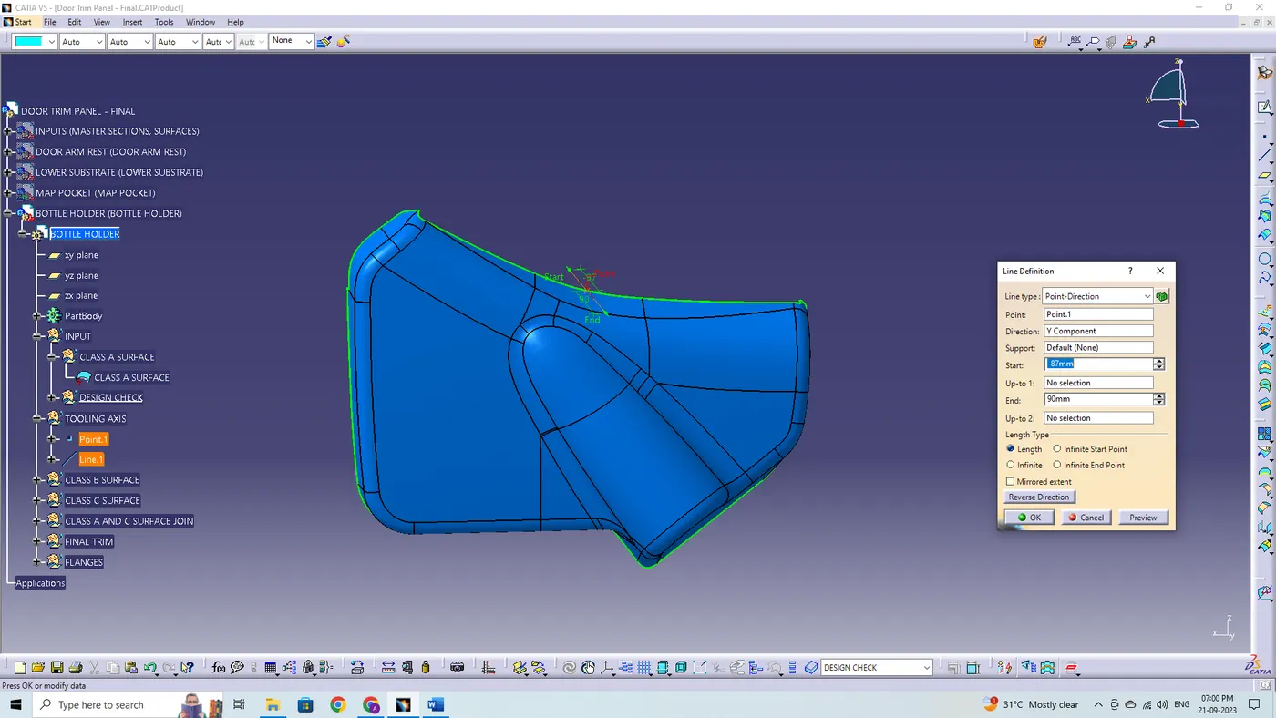
The main tooling axis has been created using the line definition feature. From the line type point direction, point has been selected and direction along Y component are selected to define the line.
DRAFT ANAYSIS:
For a class A surface, the draft analysis is to be performed to meet the requirement of the draft angle to the required tooling axis. For plastic components the minimum angle required for the draft to be 3 degrees.
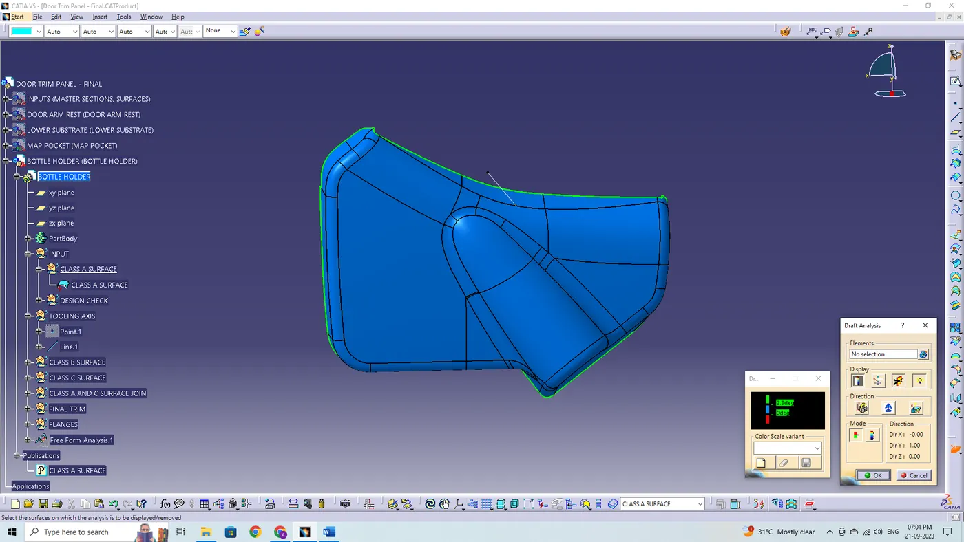
The direction compass is to be selected and placed on the main tooling axis line and the compass is being locked using the lock feature in the direction.
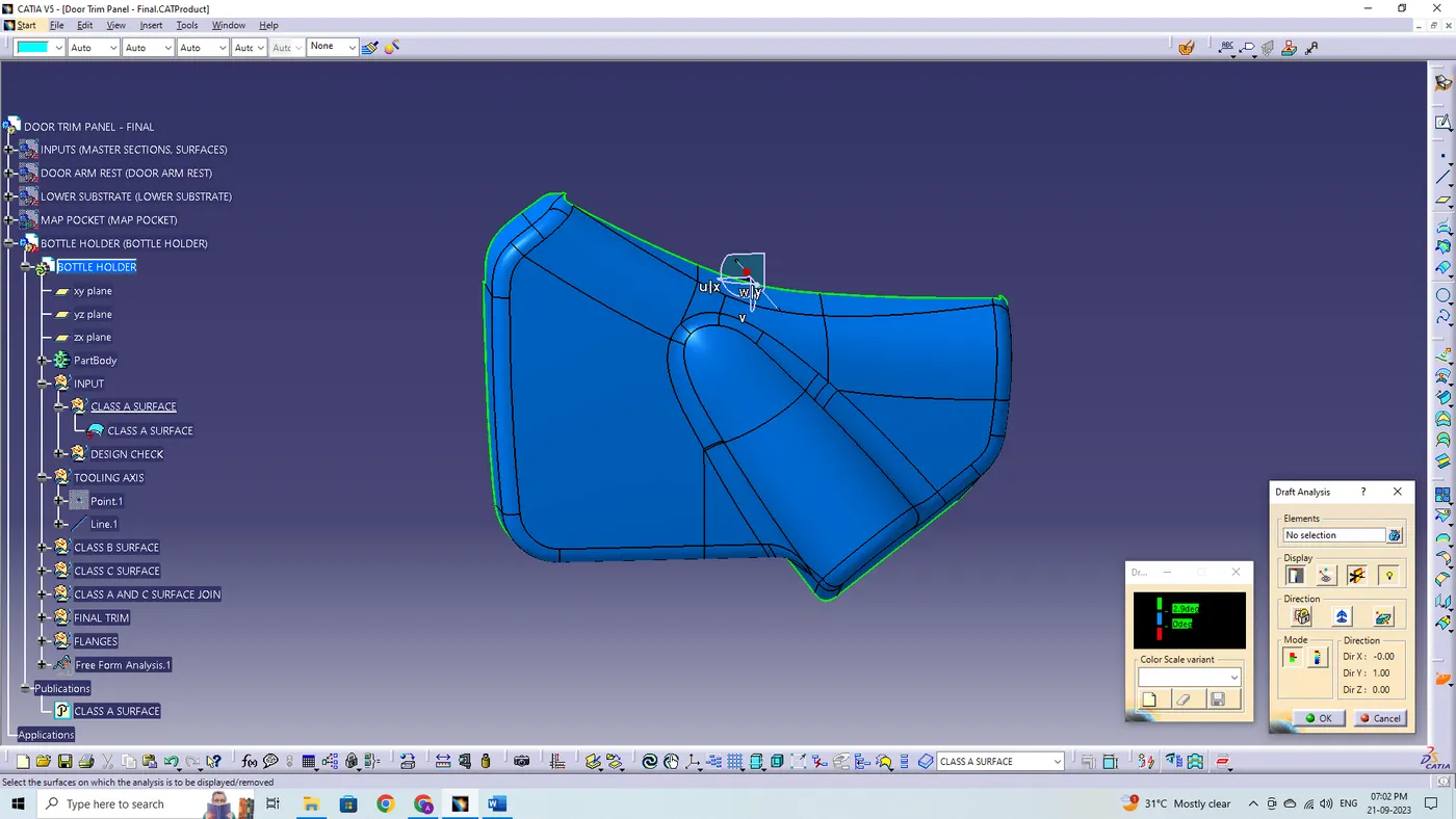
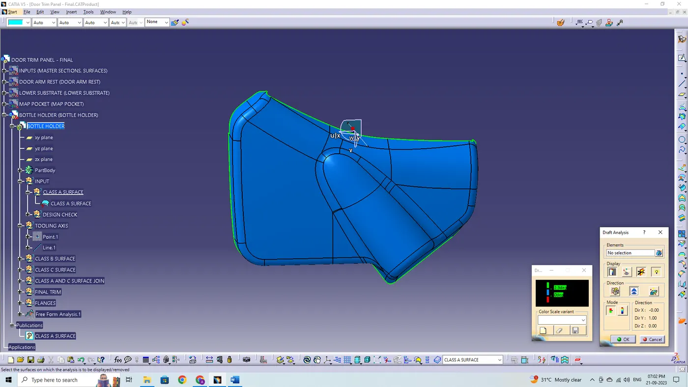
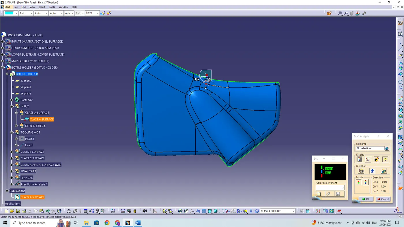
In the display window the colour code variants are being selected, to know the range of the draft in the class A surface. In the display window the colour variants show,
- For 3 degree - Green color variant (Positive)
- For 0 degree - Blue color variant
- For <0>
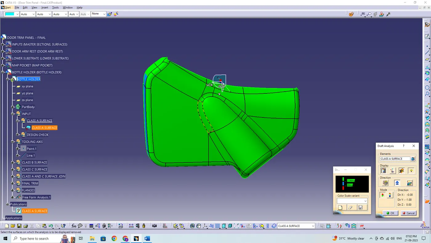
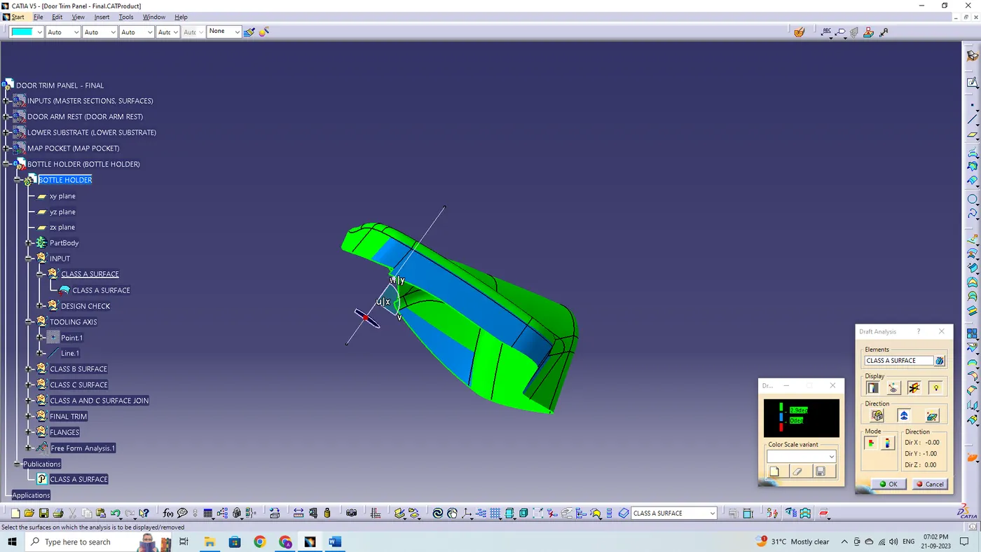
The draft analysis is being performed in both the core and cavity side of solid body. The green colour implies the draft angle are in the positive region. If the draft angle is being inverted the colour of the surface are implied as blue colour.
CREATION OF CLASS 'B' SURFACE:
By using the class A surface, the class B surface is created by offsetting to the respective length to the respective direction. By using the offset surface definition the class A surface are been offset to the length of 2.5 mm to the respective direction.
CREATING CLASS 'C' SURFACE:
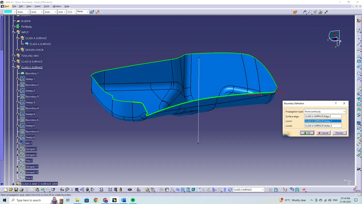
To make the class C surface, the boundaries are extracted from the class A surface. The outer boundary is being extracted using the boundary feature/extract definitions.
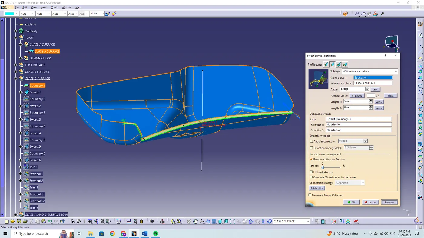
By using the sweep surface creation definition, the respective profile types are being selected and subtype with reference surface are being selected. In that the guide curve are selected as the boundary in the class A surface, and reference surface are selected, and the class C surface are being created to the respective length.
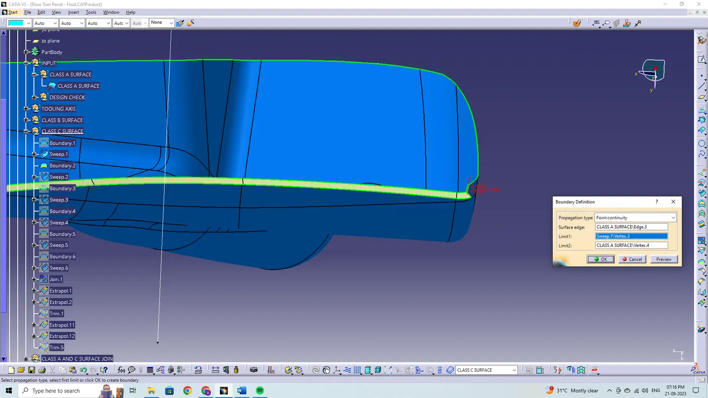
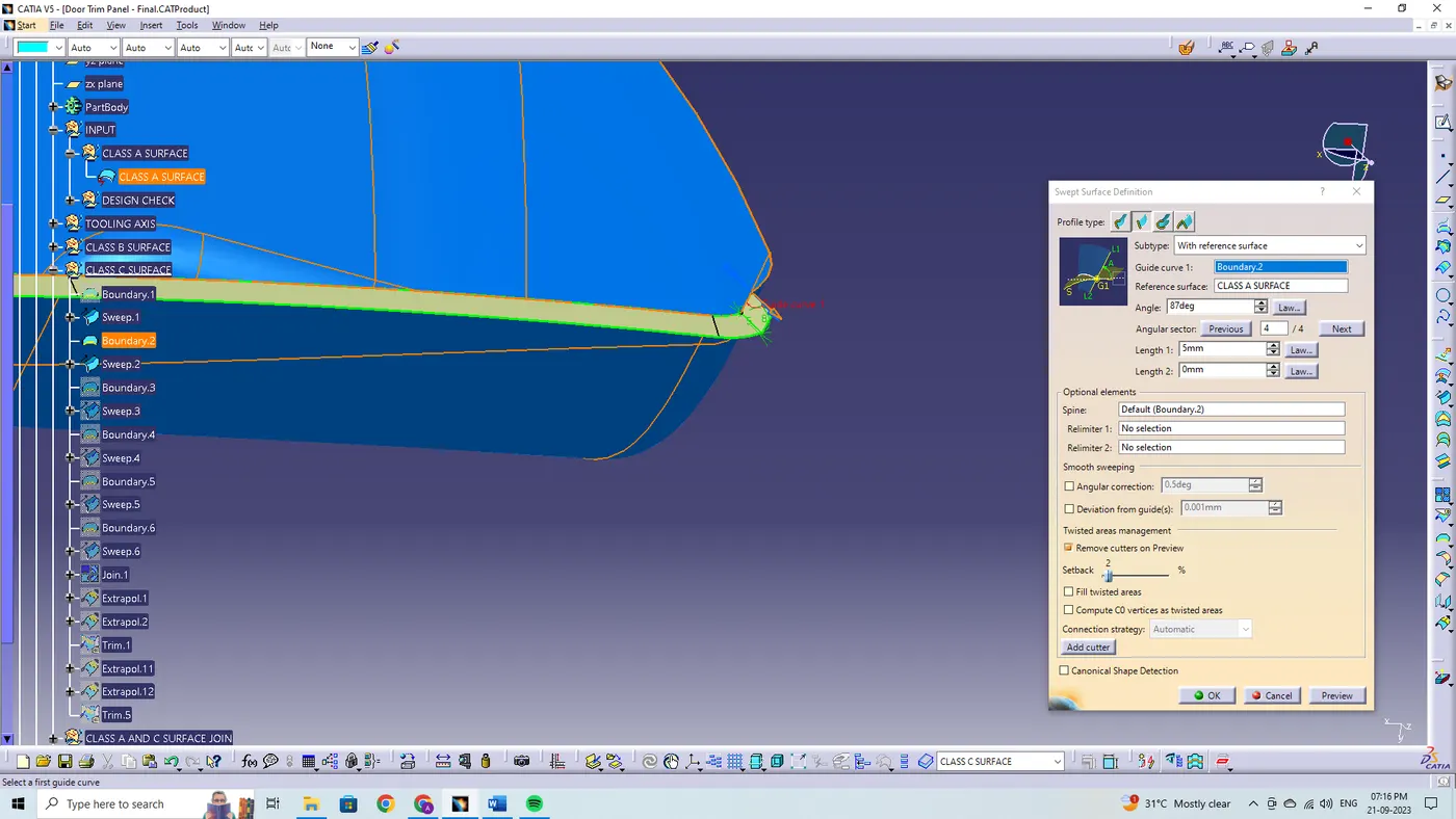
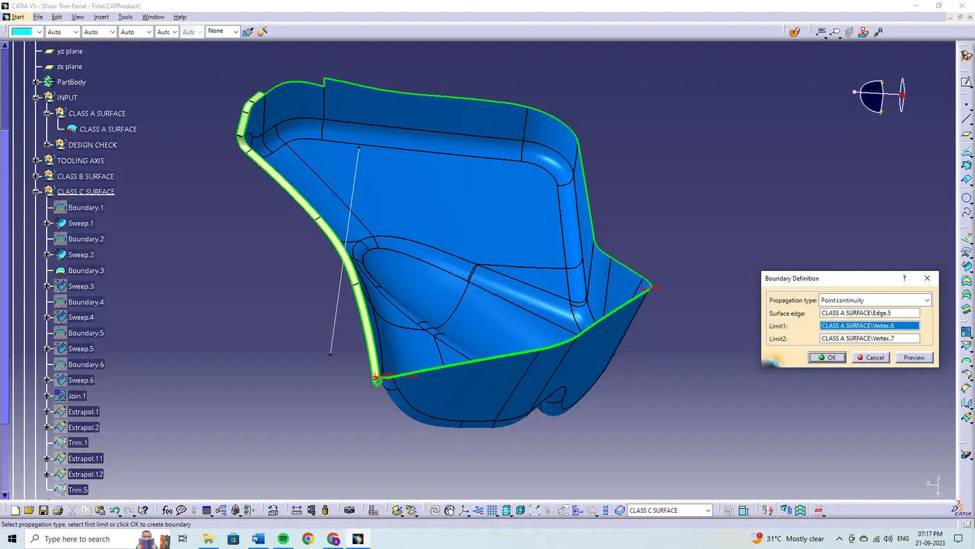
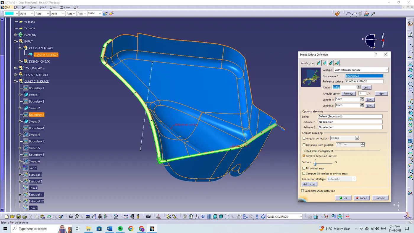
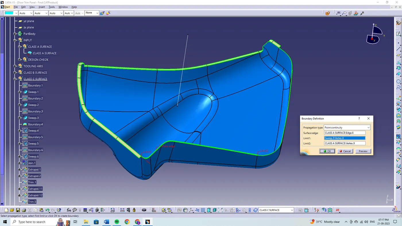
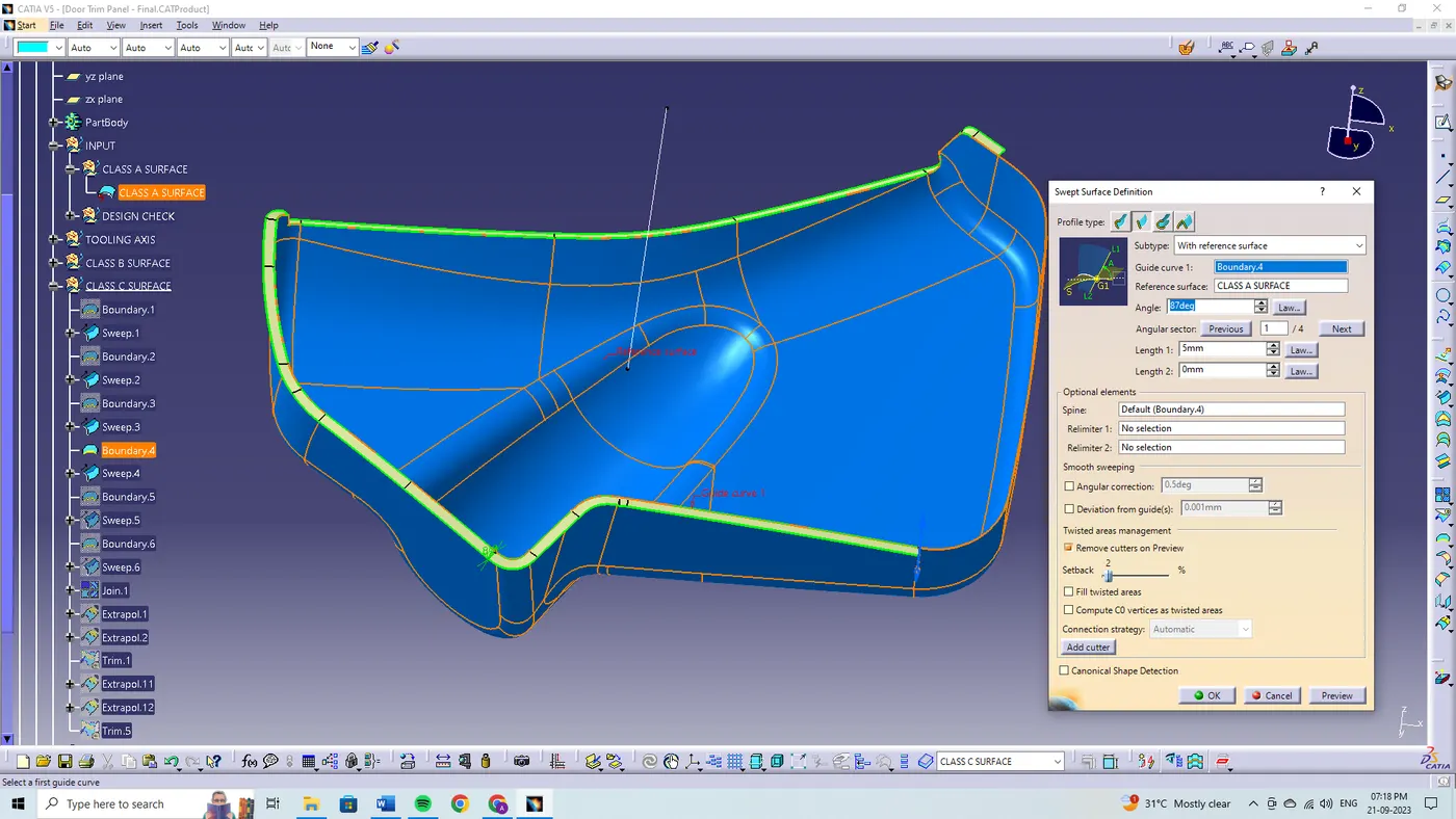
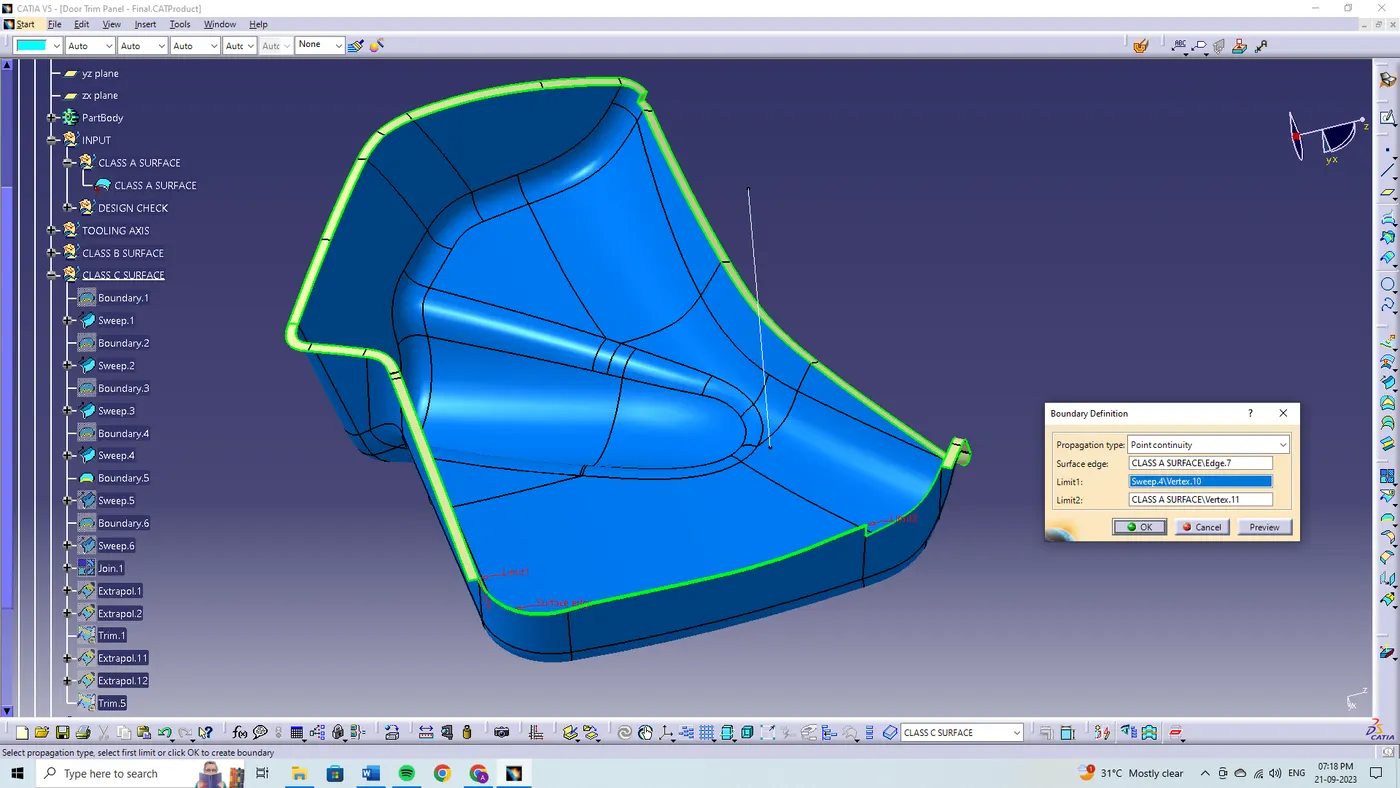
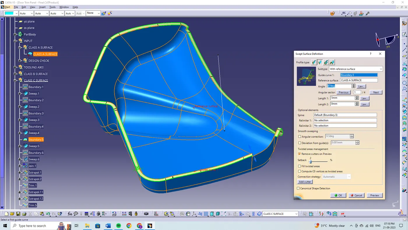
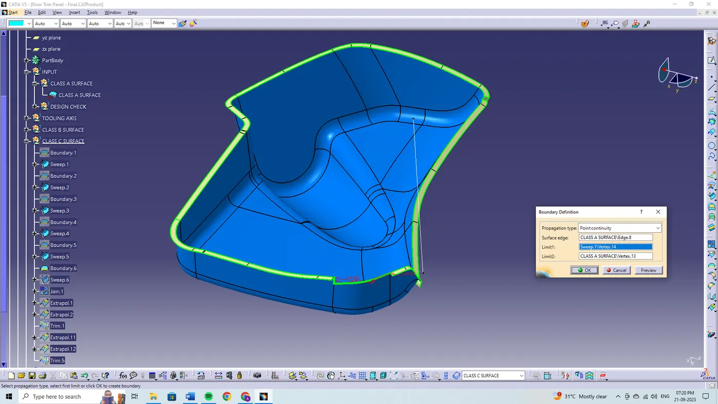
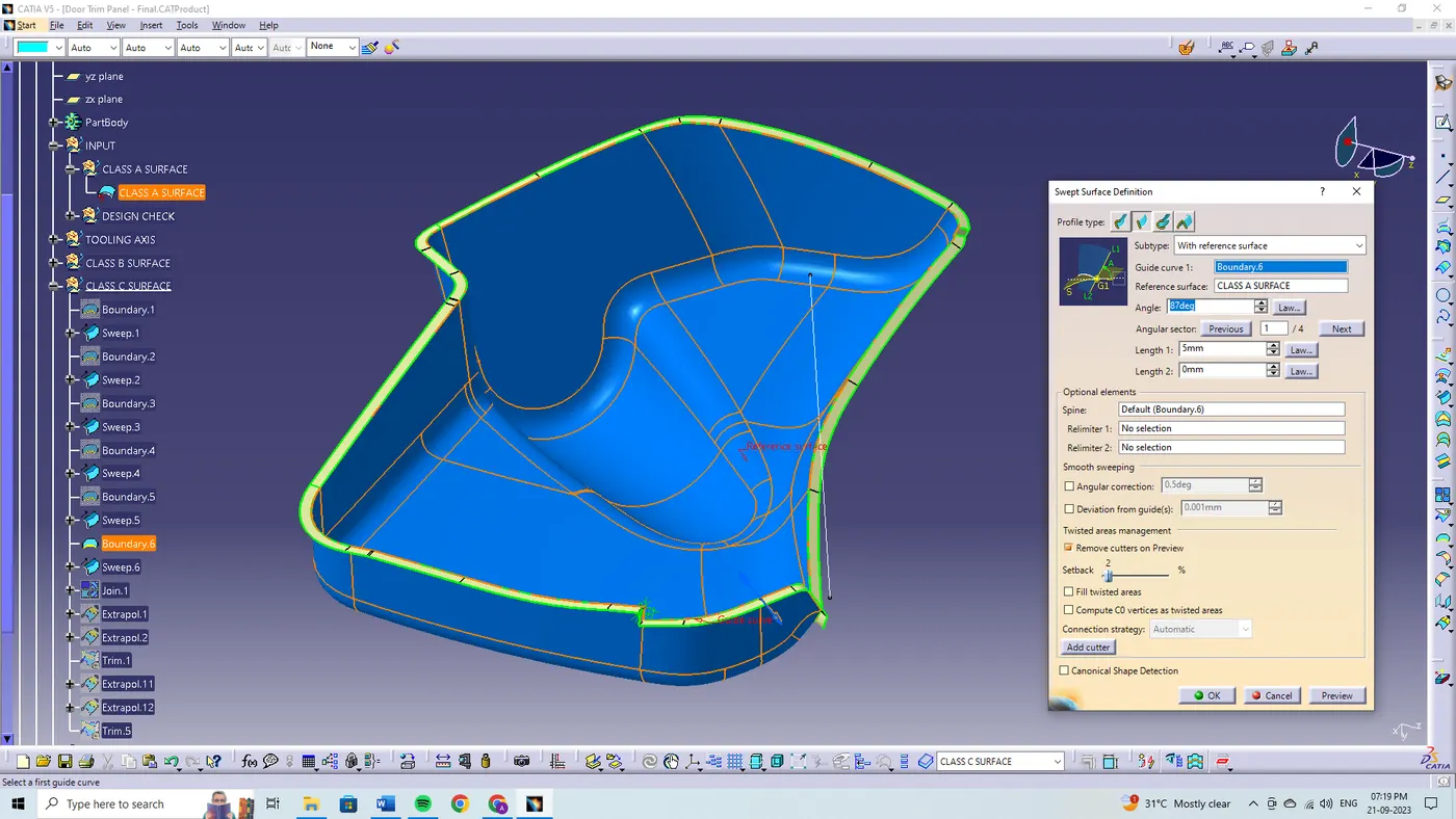
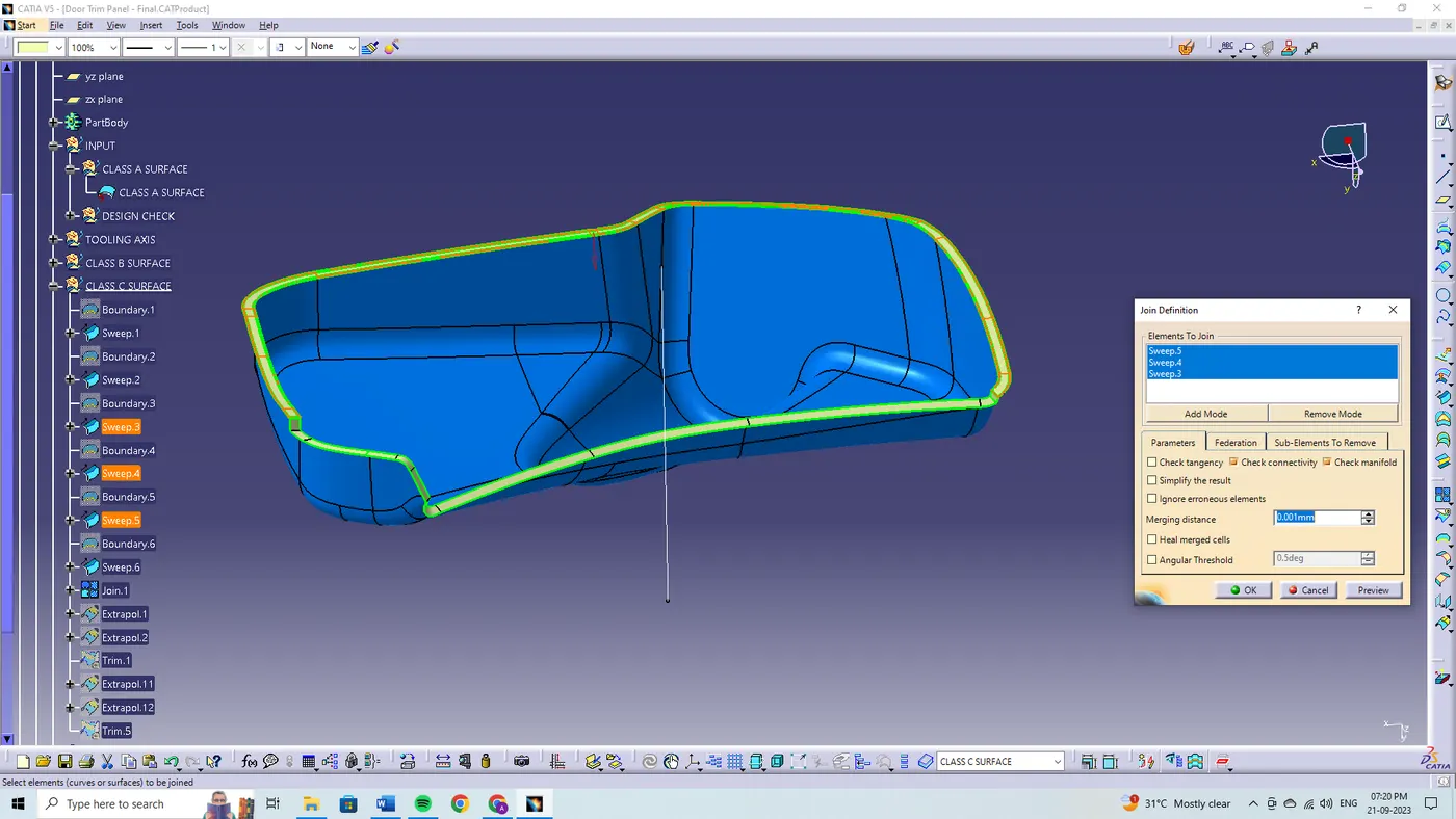
By using the join definition feature the created class C surfaces are being joined together, and by using the extrapolation and trimming feature the edges are being extrapolated and trimmed together to form the class C surfaces.
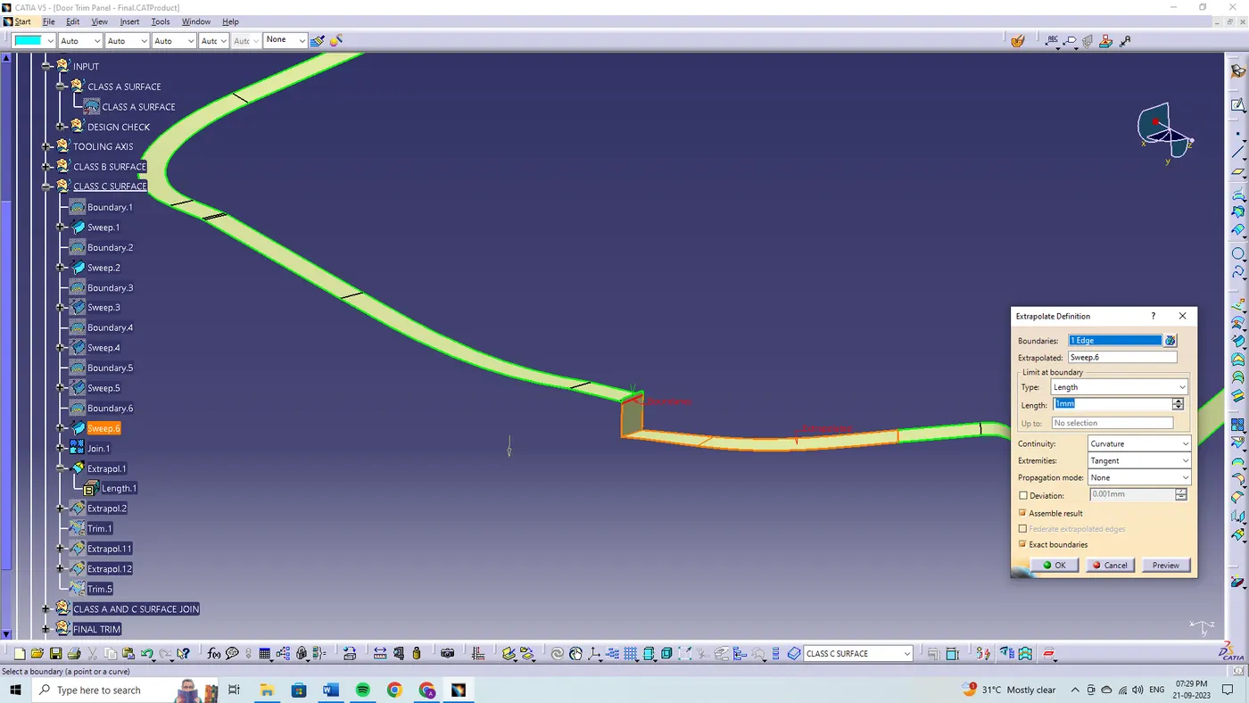
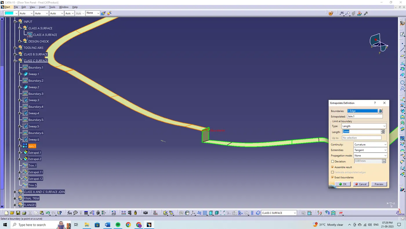
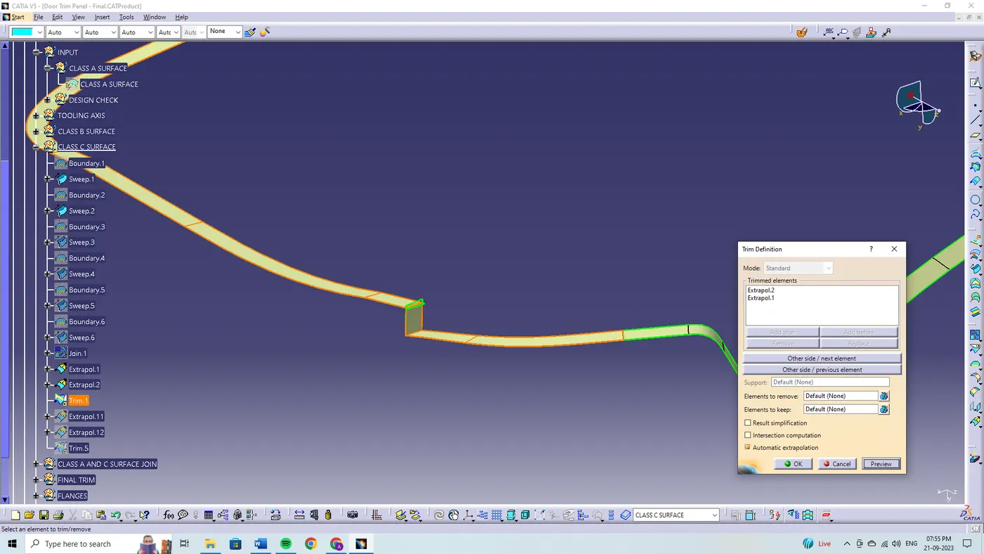
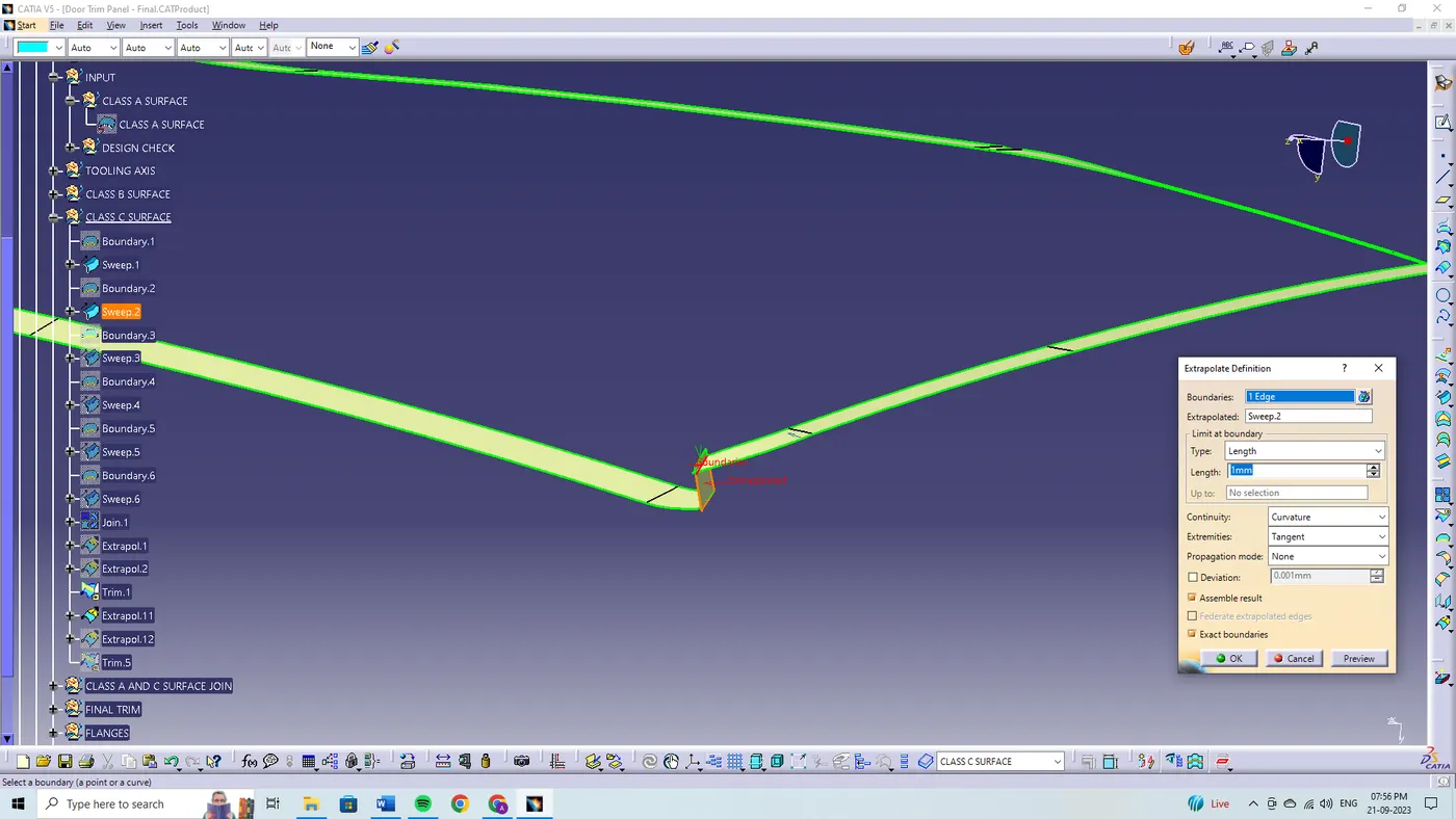
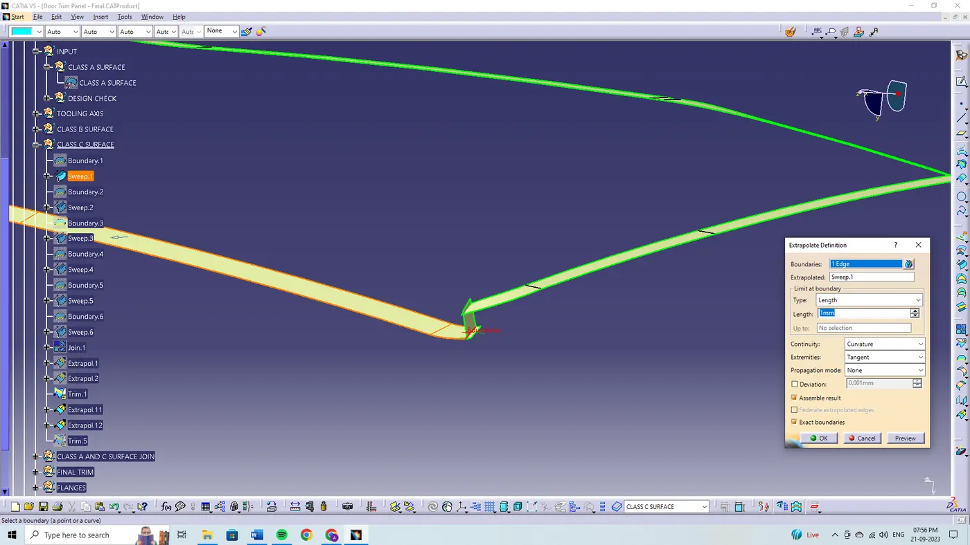
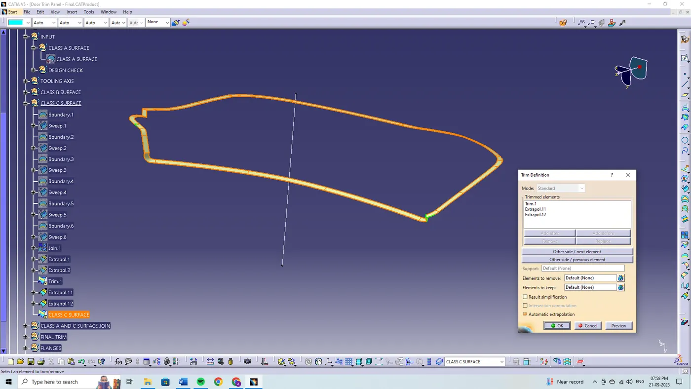
The class C surfaces are being created by using the sweep feature and the direction along the tooling direction and the reference with the surface and guide curve are being selected to form the class C surfaces.
JOINING THE CLASS A AND CLASS C SURFACES:
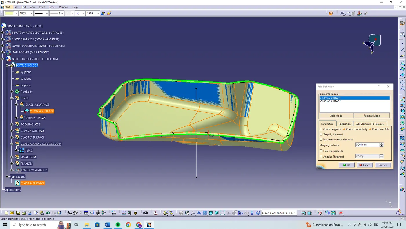
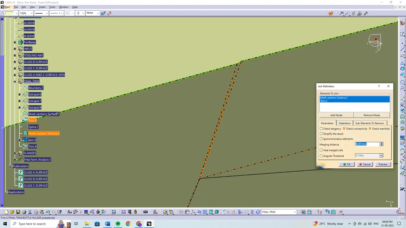
By using the join feature the class A and class C surface are joined together with the merging distance of 0.001 mm.
FINAL TRIMMING:
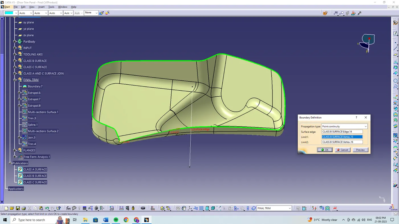
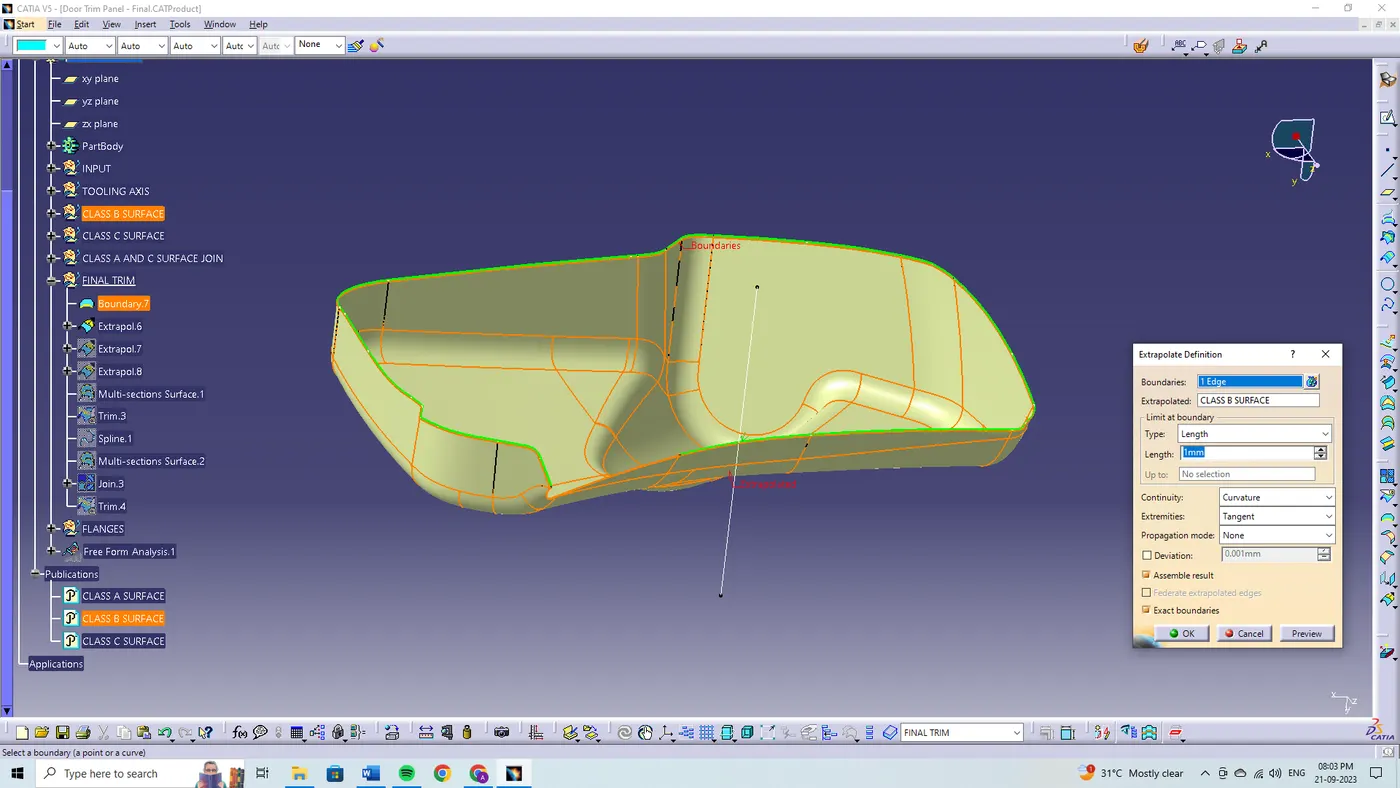
By using the intersection feature the first element and second element are being selected to check the intersection between the created class B and joined class (A+C).
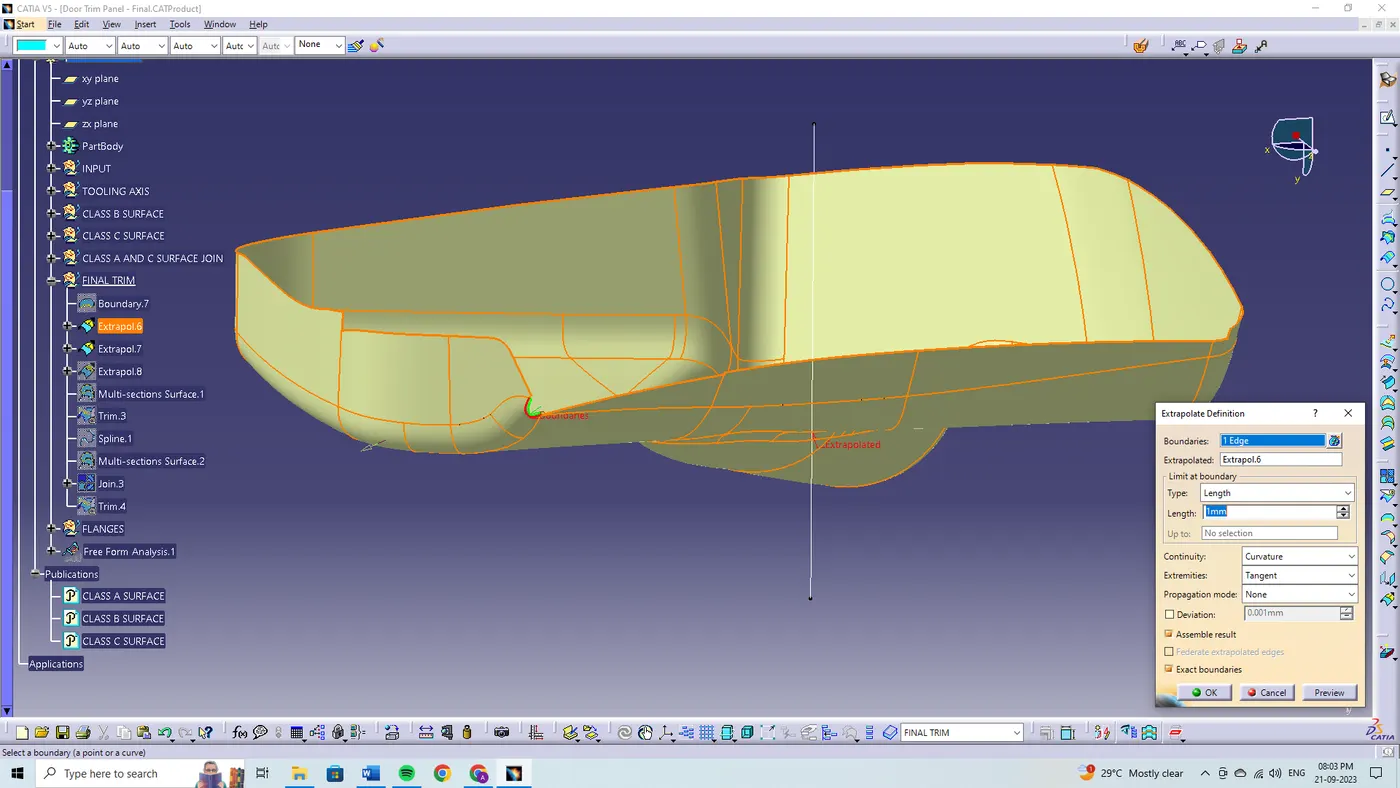
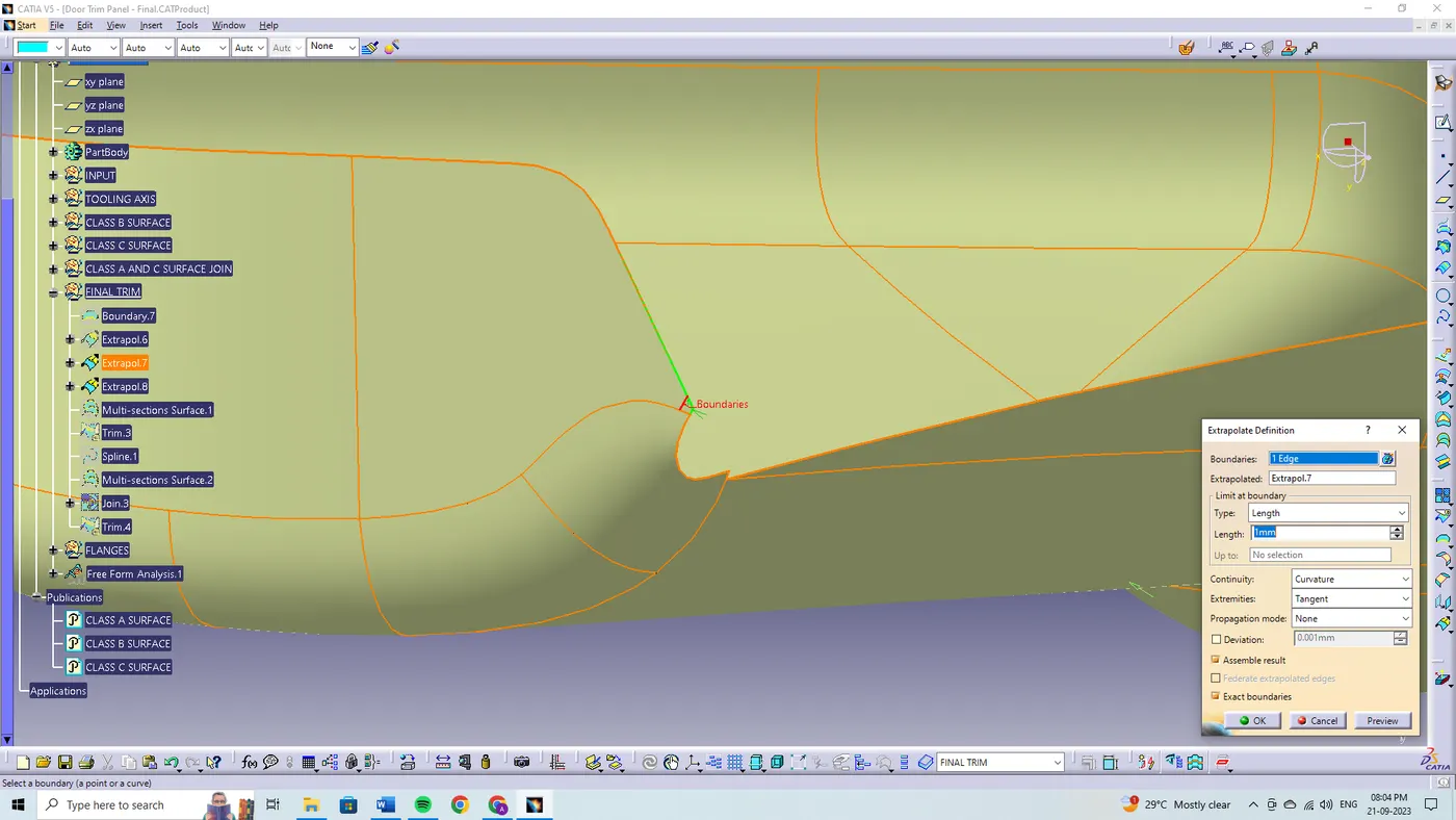
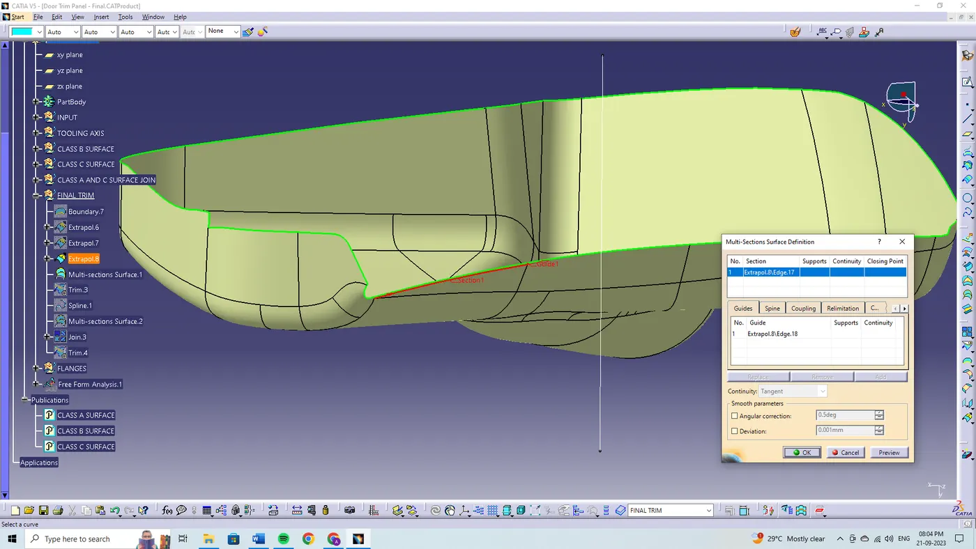
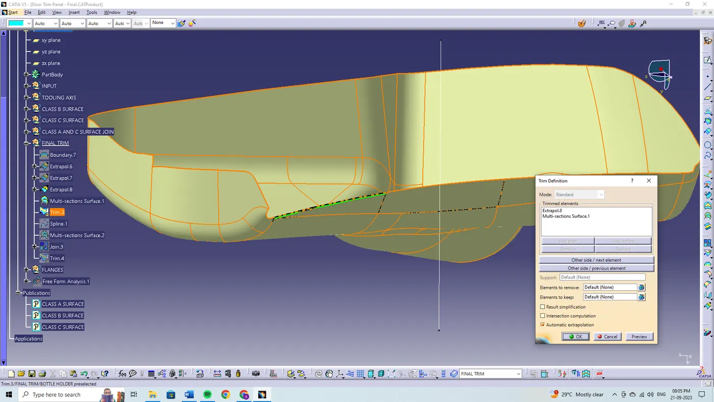
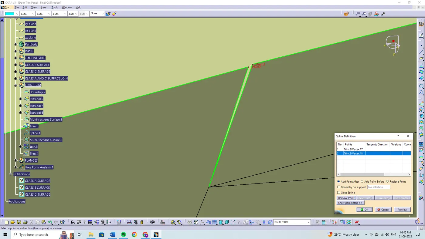
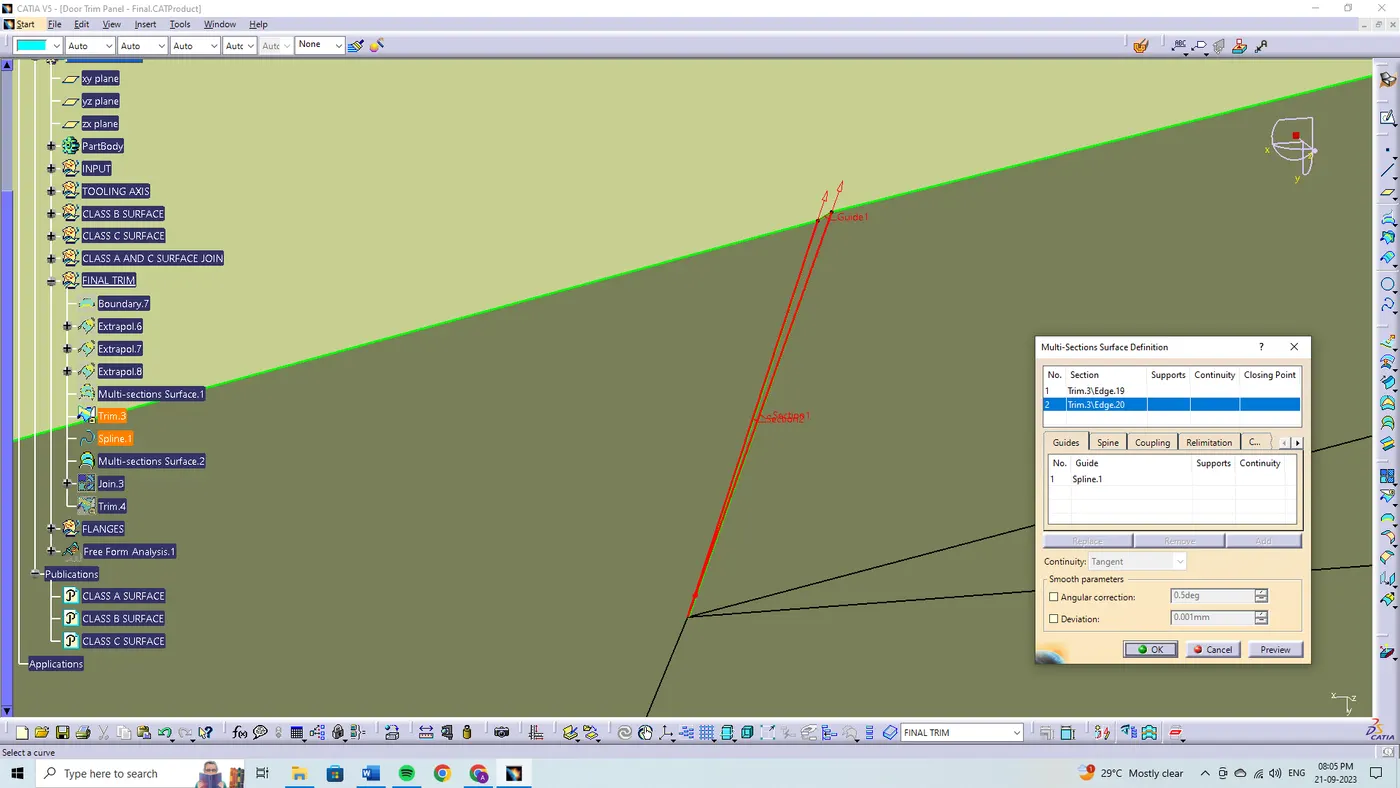
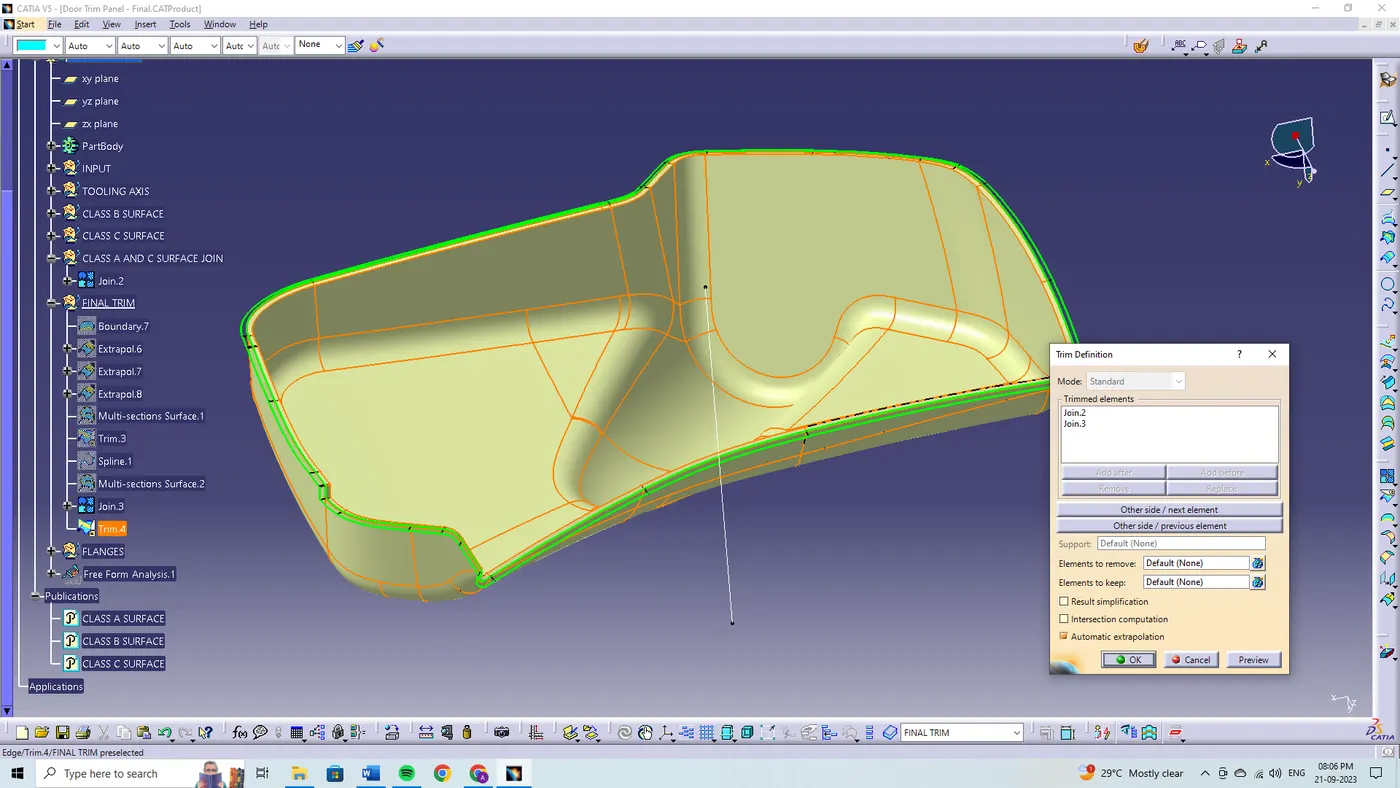
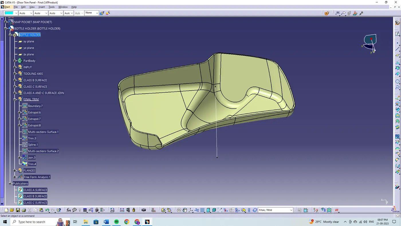
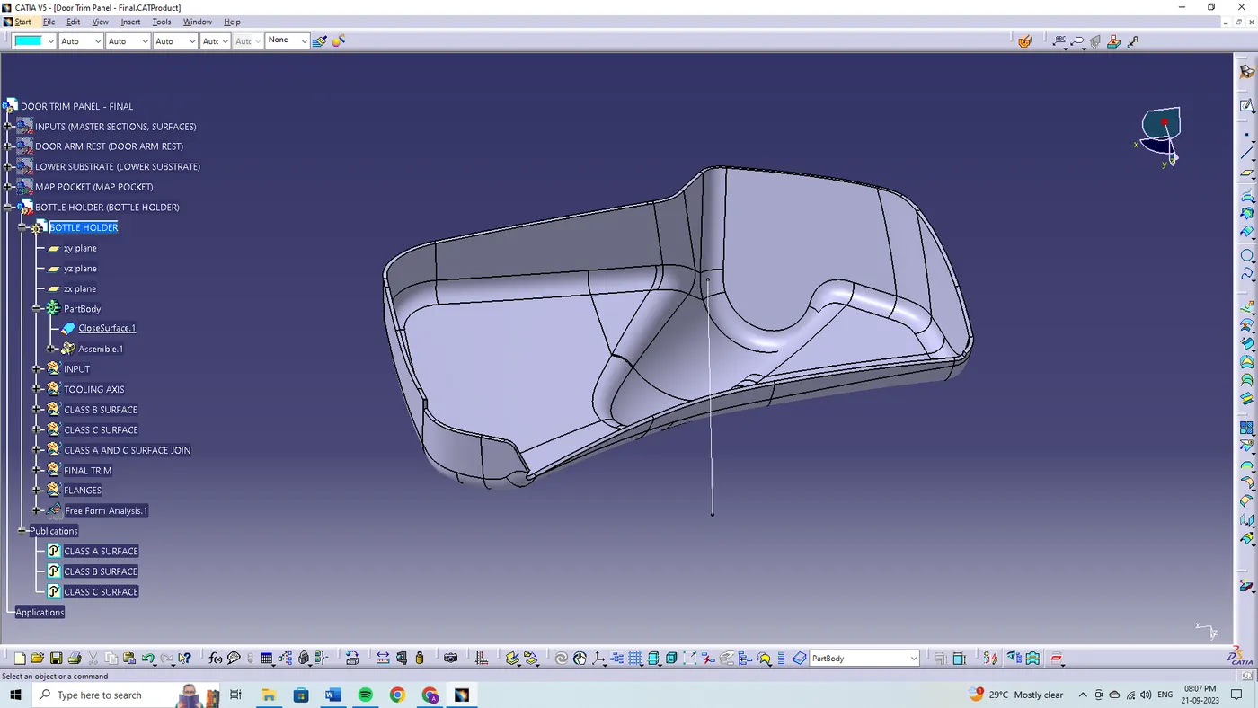
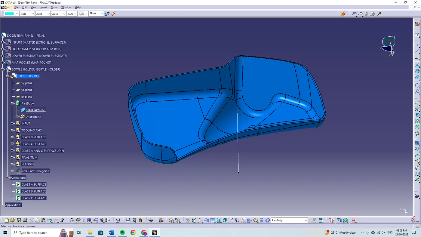
CLOSED SURFACE:
By using the close surface definition, the part surface is selected to make them into solid part from the part workbench.
DRAFT ANALYSIS:
The draft analysis has been performed on the final component created as a closed body using the part design closed surface feature. For plastic components the minimum angle required for the draft to be 3 degrees.
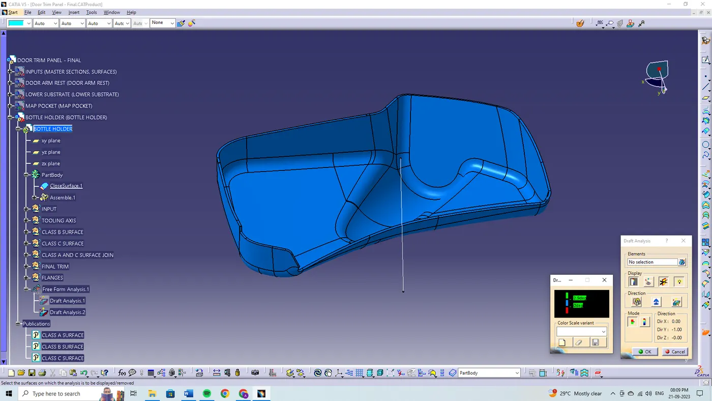
The direction compass is to be selected and placed it on the main tooling axis line and the compass are being locked using the lock feature in the directions.
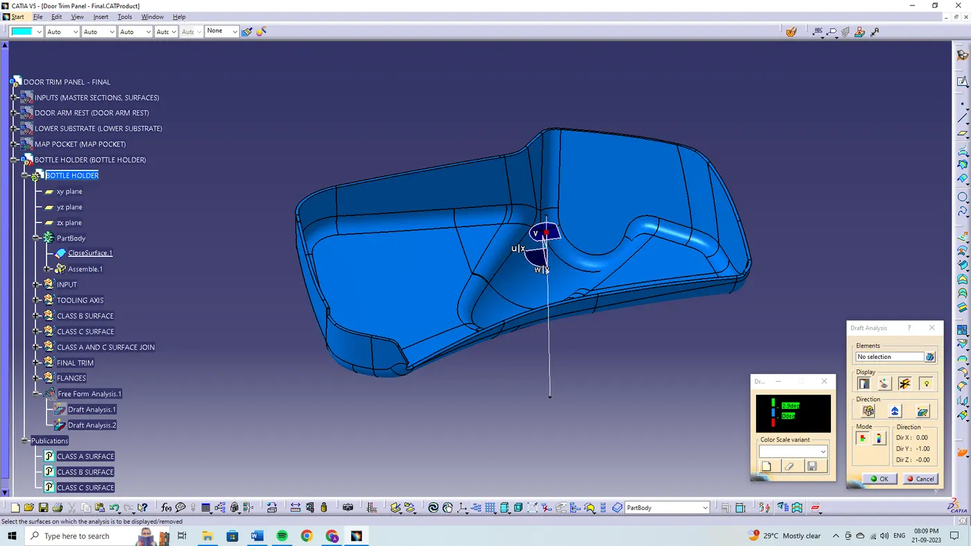
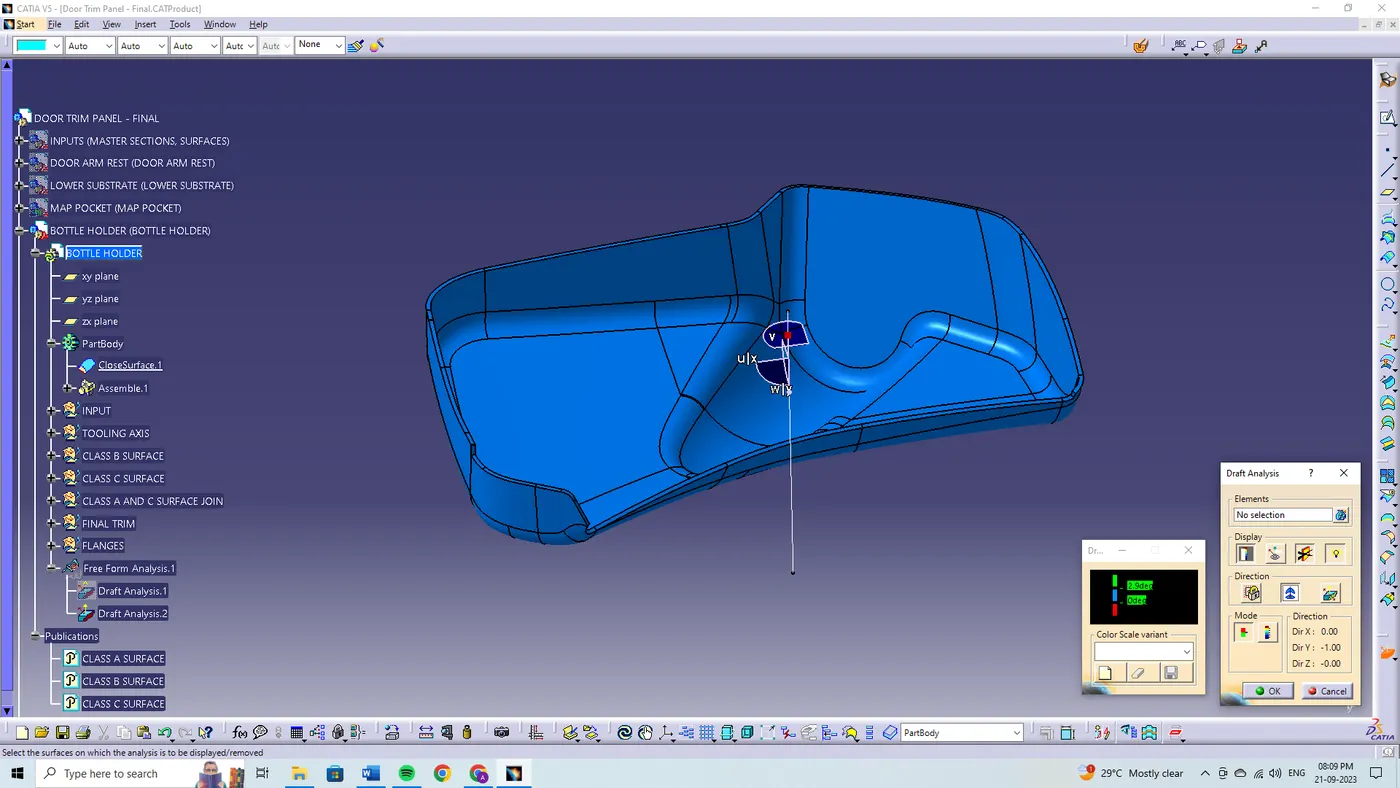
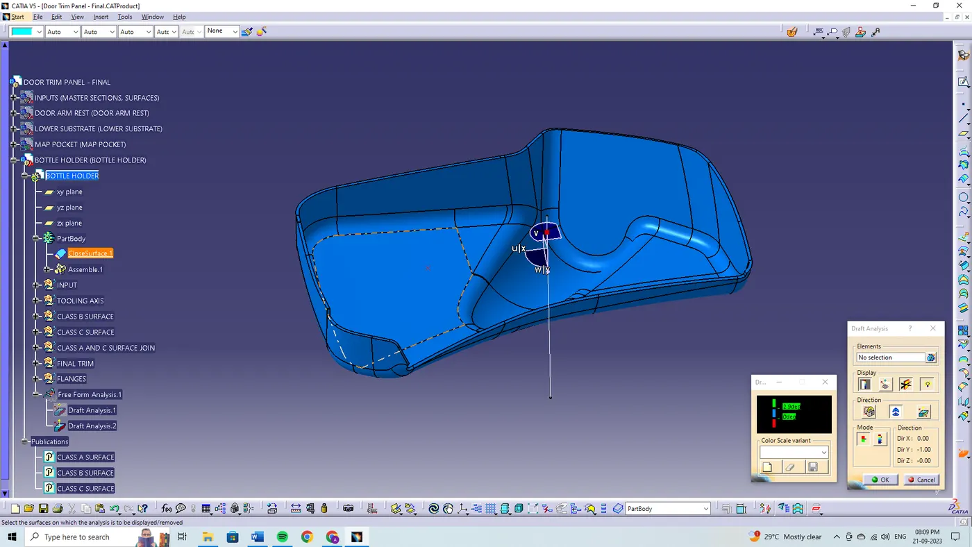
In the display window the colour code variants are being selected, to know the range of the draft in the class A surface. In the display window the colour variants show,
- For 3 degree - Green color variant (Positive)
- For 0 degree - Blue color variant
- For <0>
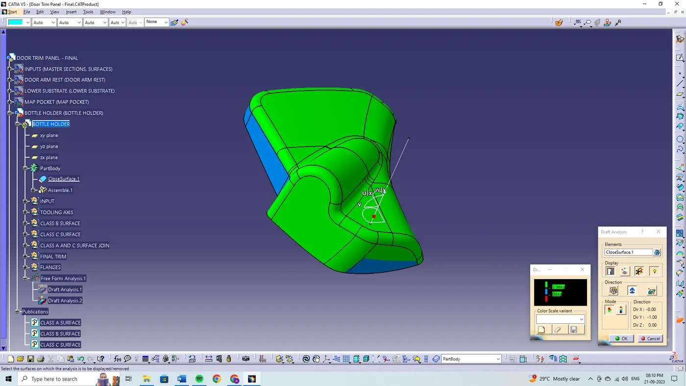
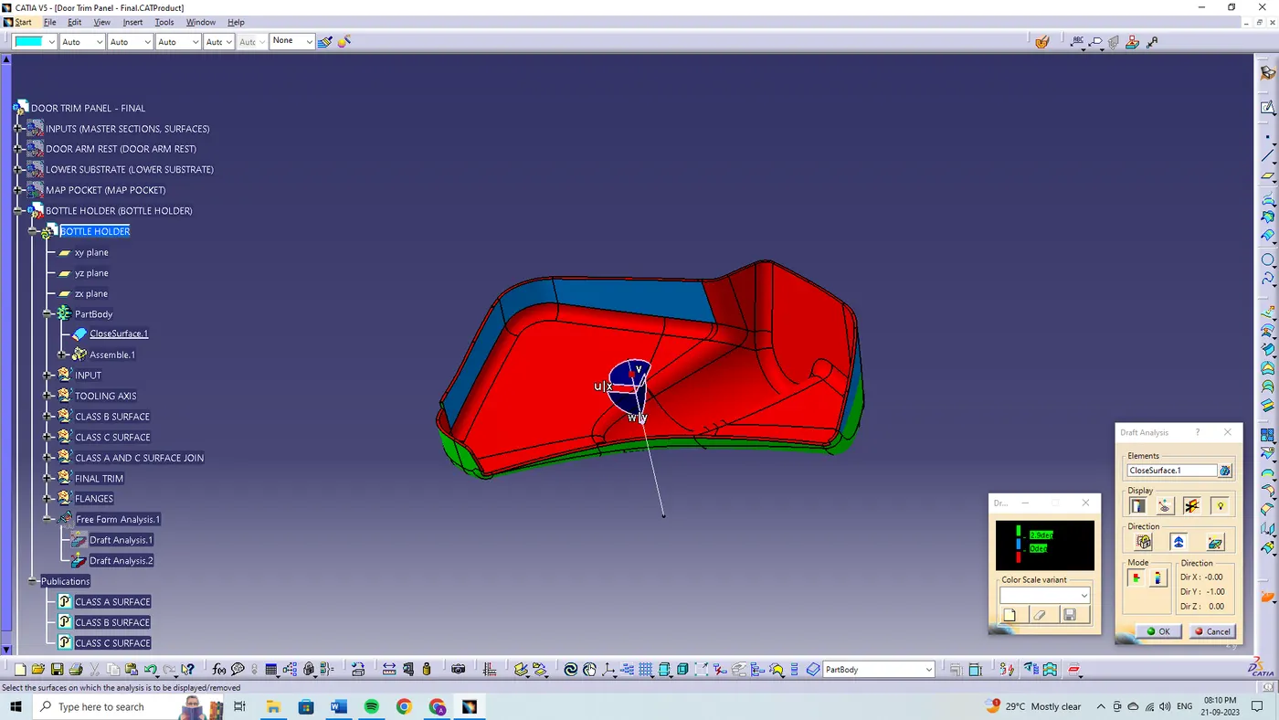
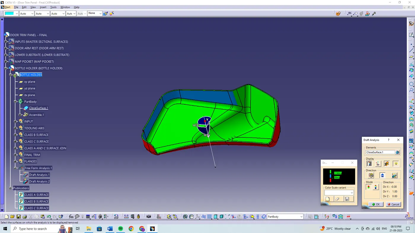
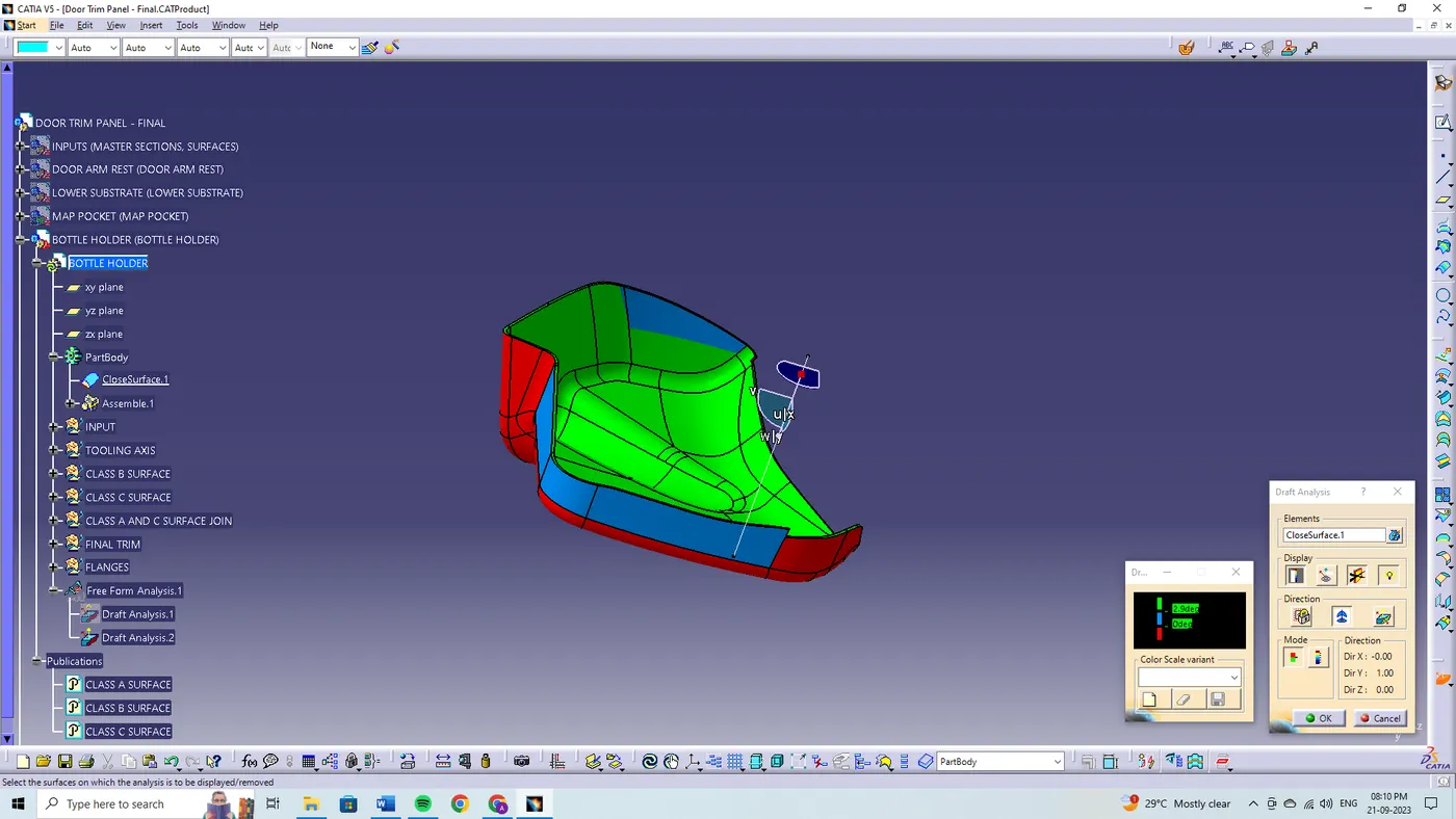
The draft analysis is being performed in both the core and cavity side of solid body. The green colour implies the draft angle are in the positive region. If the draft angle is being inverted the colour of the surface are implied as blue colour.
HEAT STAKE:
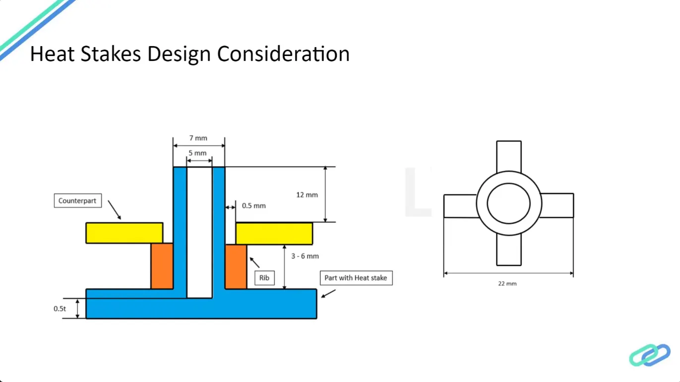
Heat Staking, also known as thermoplastic staking, is the process of joining two similar/dissimilar materials together. In heat staking, it uses local heating and cooling to raise the temperature of plastic components and allow plastic reforming to be carried out.
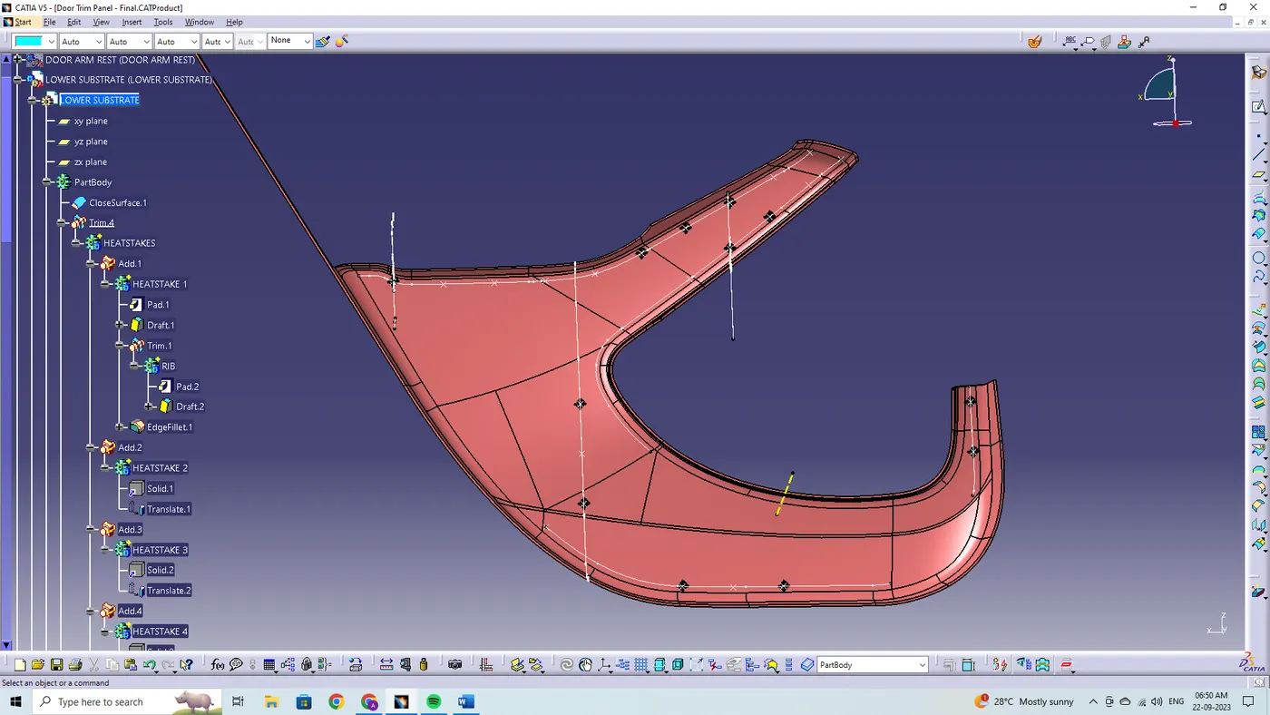
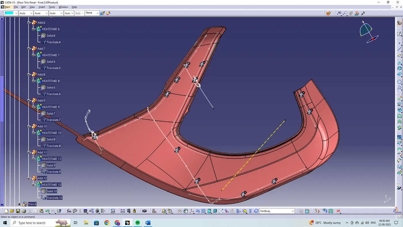
CONSTRUCTION OF HEAT STAKES:
By using the master section, the inner diameter, outer diameter, and length of the heat stakes are being measured.
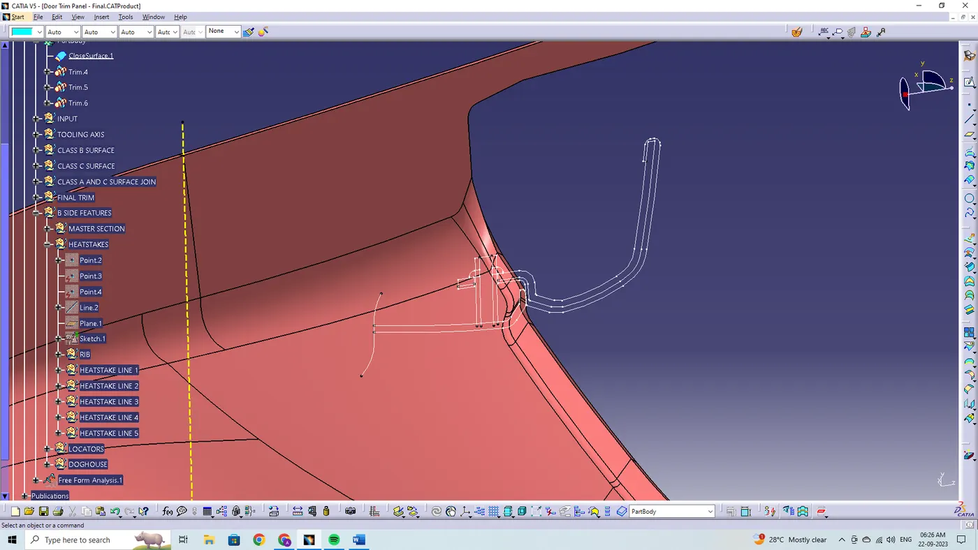
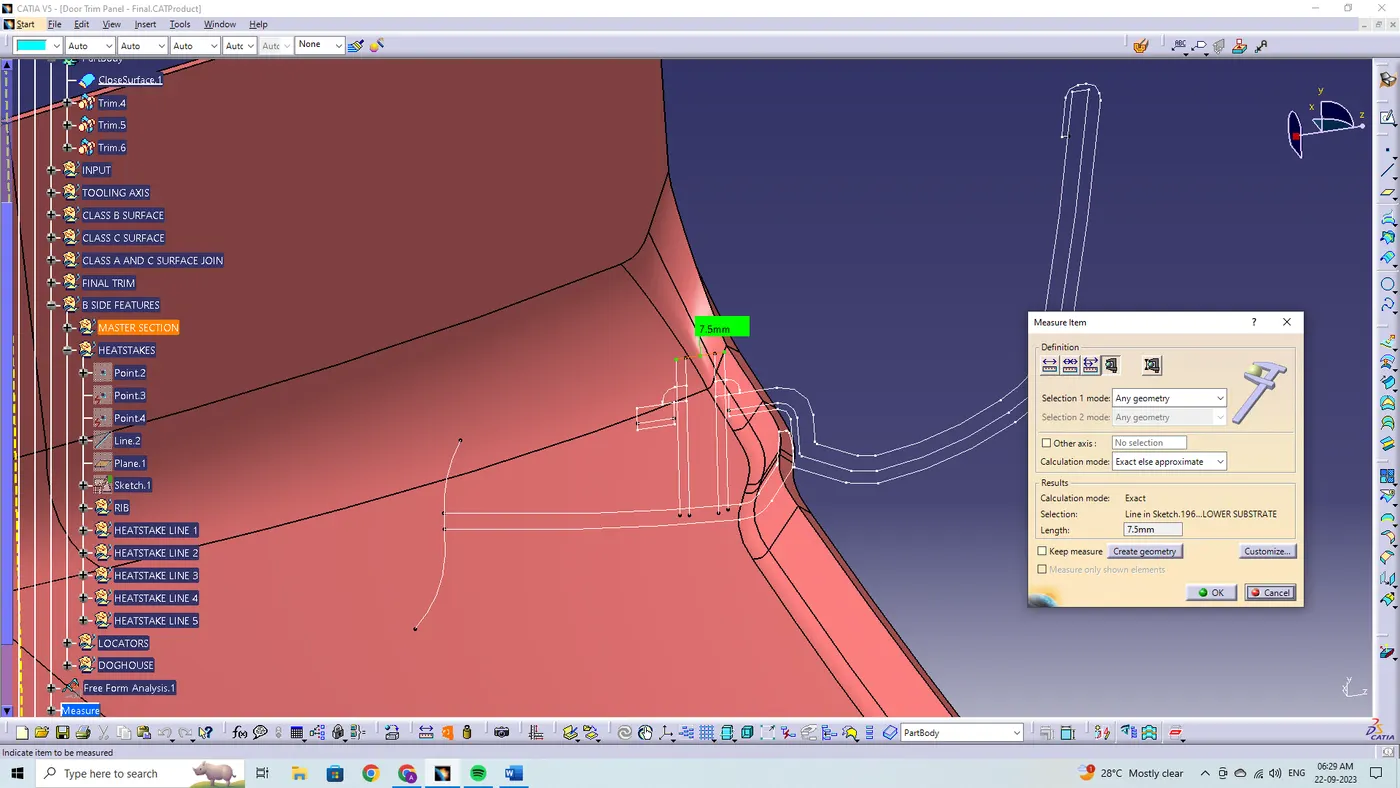
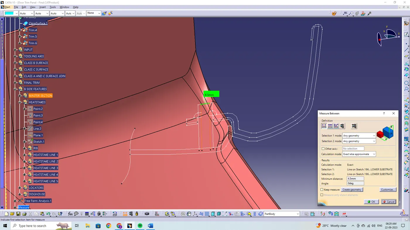
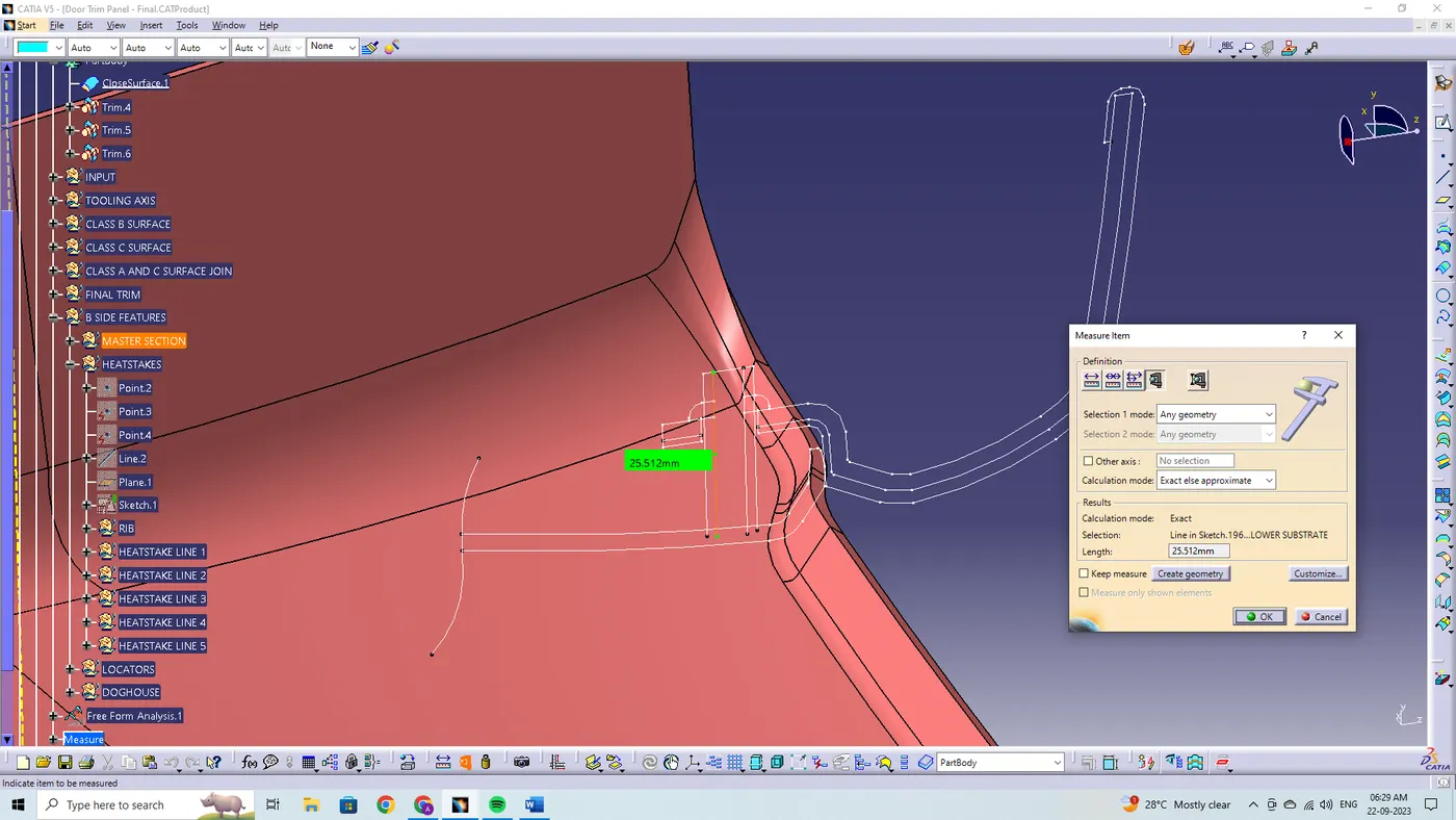
By using the point definition feature the points are created between two points to make the center point at the heat stakes.
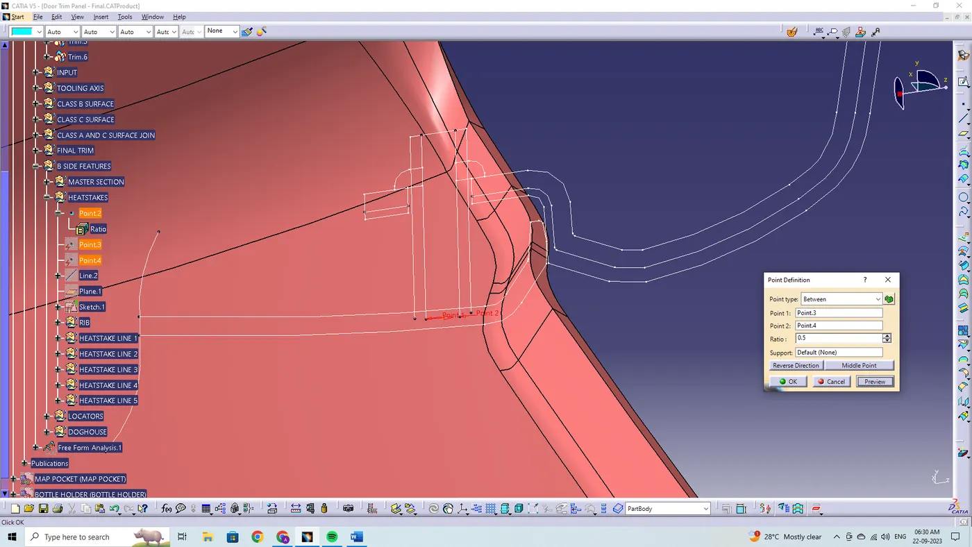
By using the plane definition feature the respective planes are being created at the point reference. By using the plane and the projection point, positioned sketches are being created to sketch the profile of the heat stake with respective inner diameter and outer diameter.
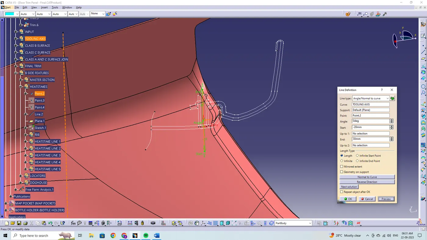
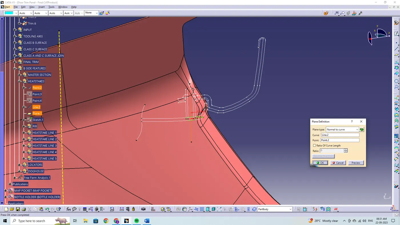
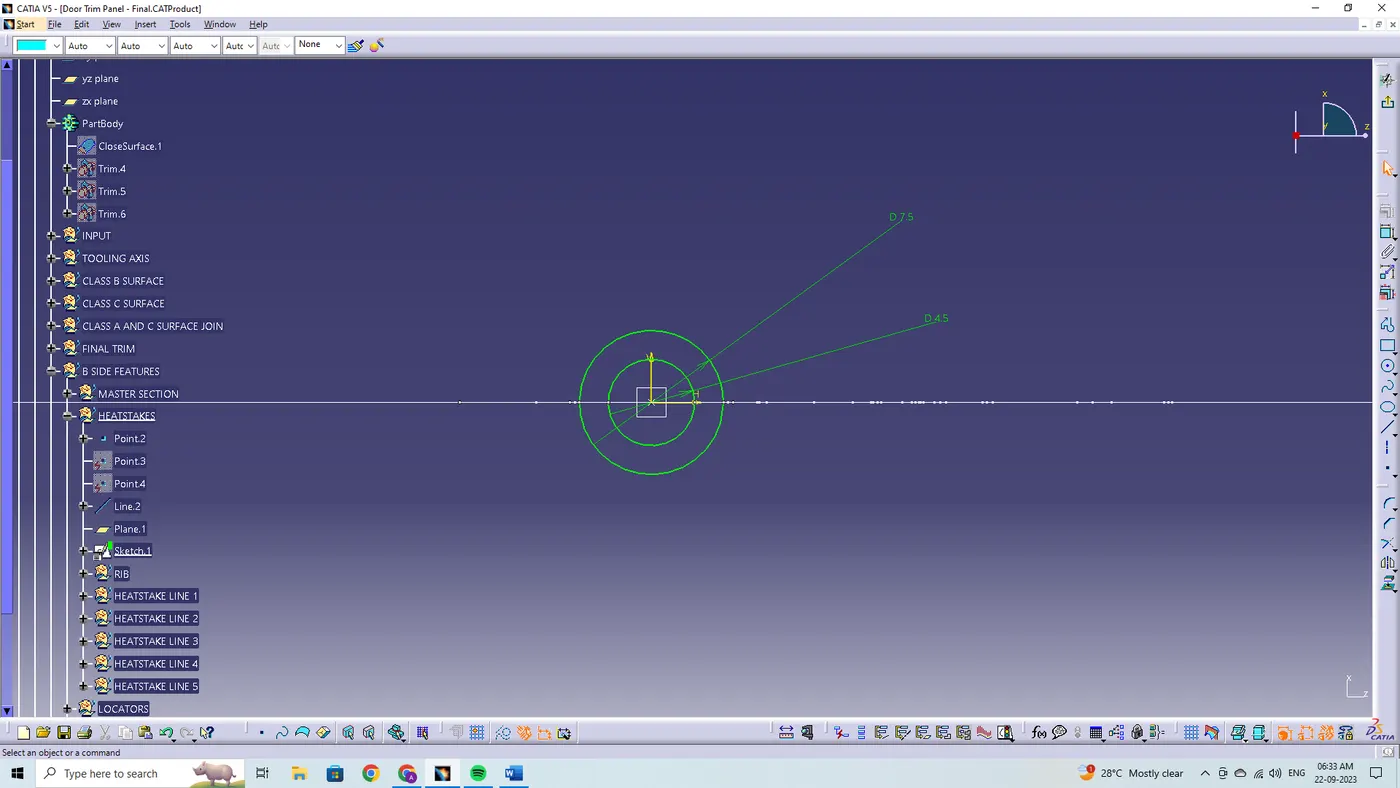
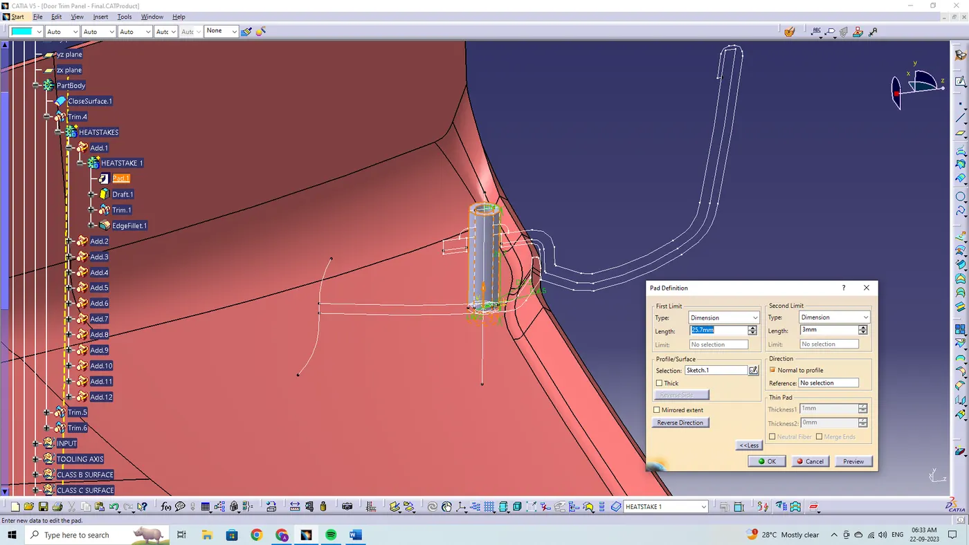
By using the pad definition, the 2-D sketches are being extruded and the first and second limit are being defined to the respective length to the respective direction.
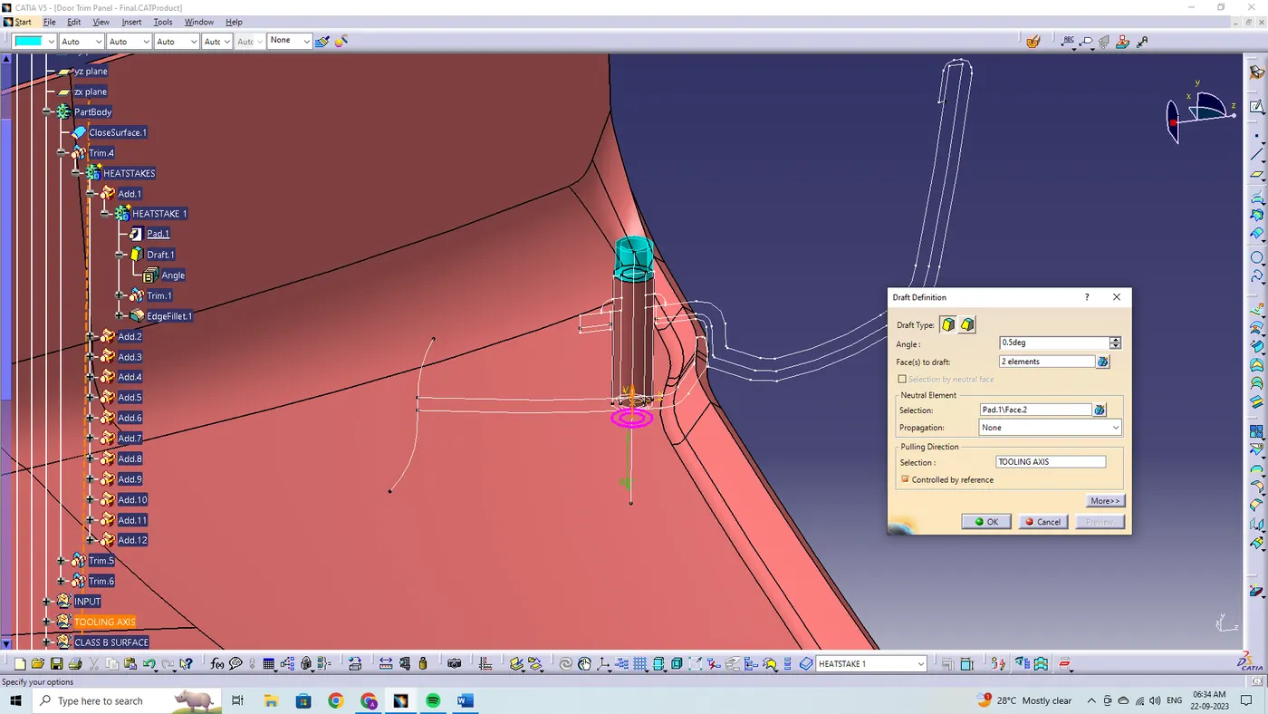
By using the draft definition, the faces are being selected to draft and the pulling direction are being selected as a main tooling axis also the neutral element to draft are being selected.
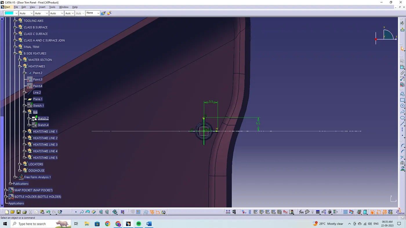
For the support for the heat stake bosses the supporting ribs are being added to the screw side faces. For that the supporting rib sketch are been drawn and by using the pad definition the 2-D sketch are being extruded to the respective lengths.
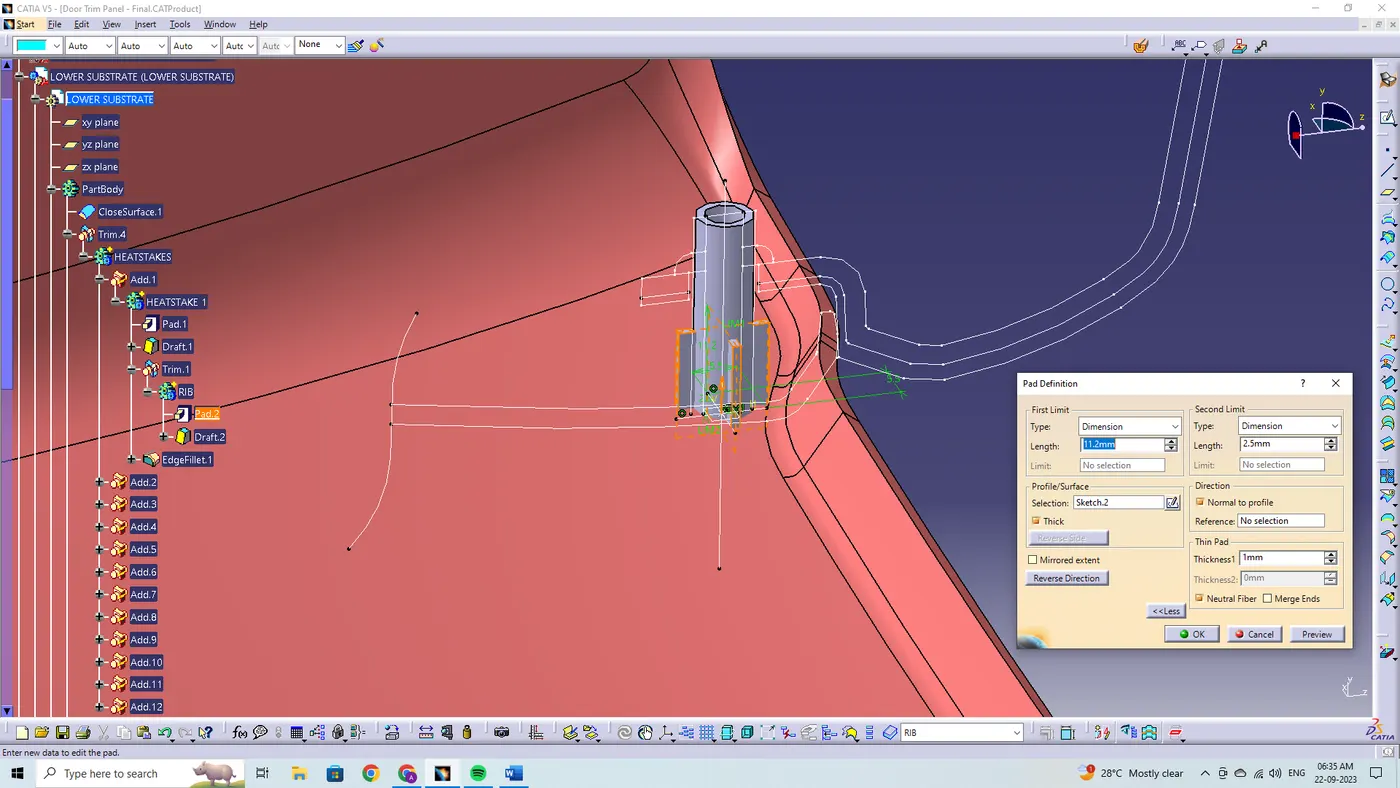
By using the draft definition, the faces are being selected to draft and the pulling direction are being selected as a main tooling axis also the neutral element to draft are being selected.
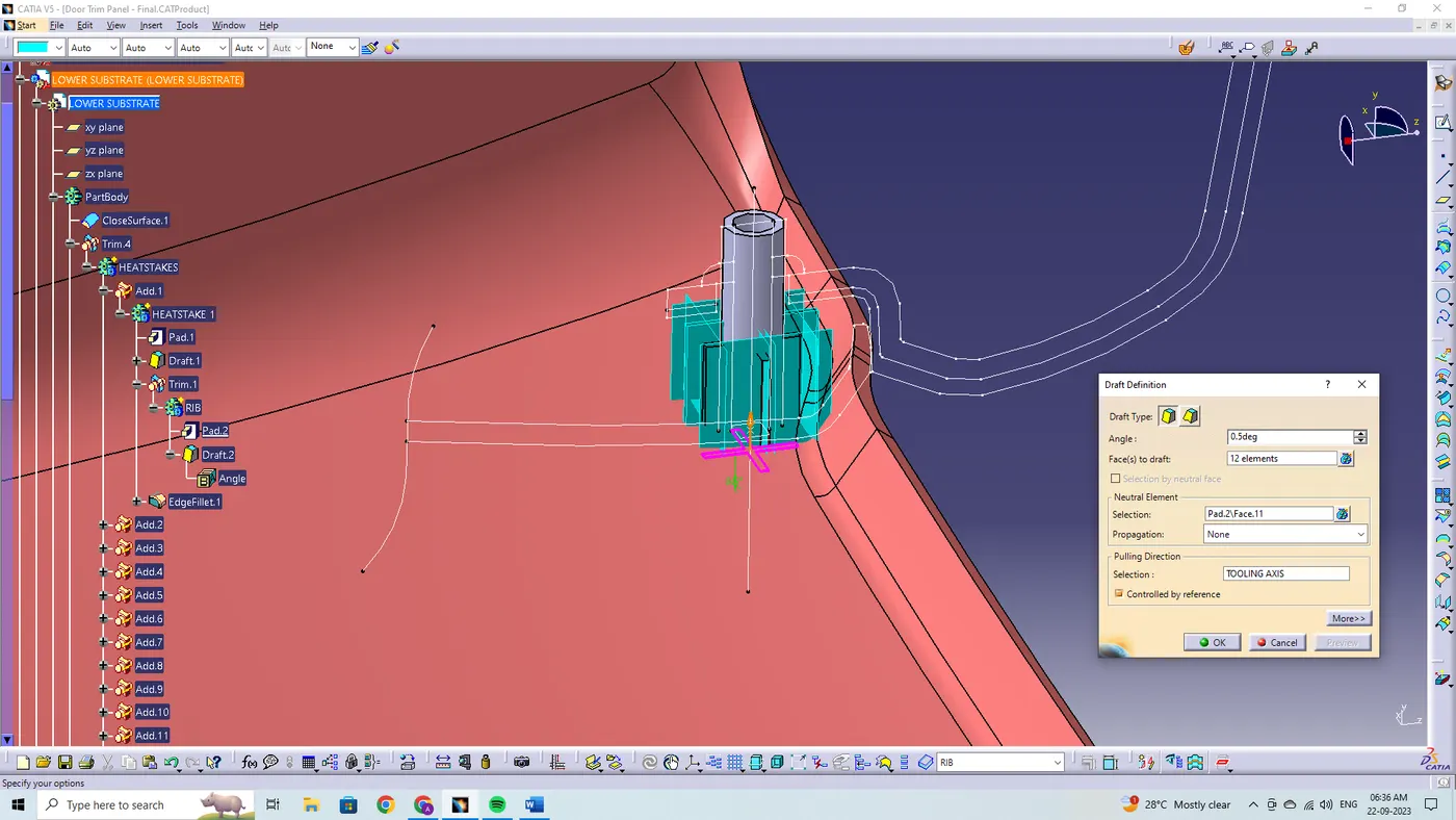
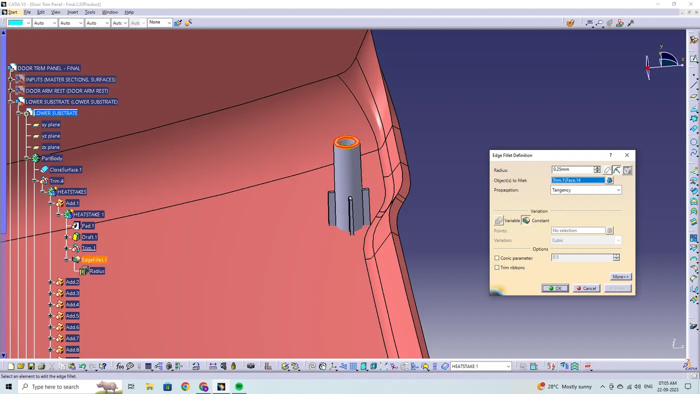
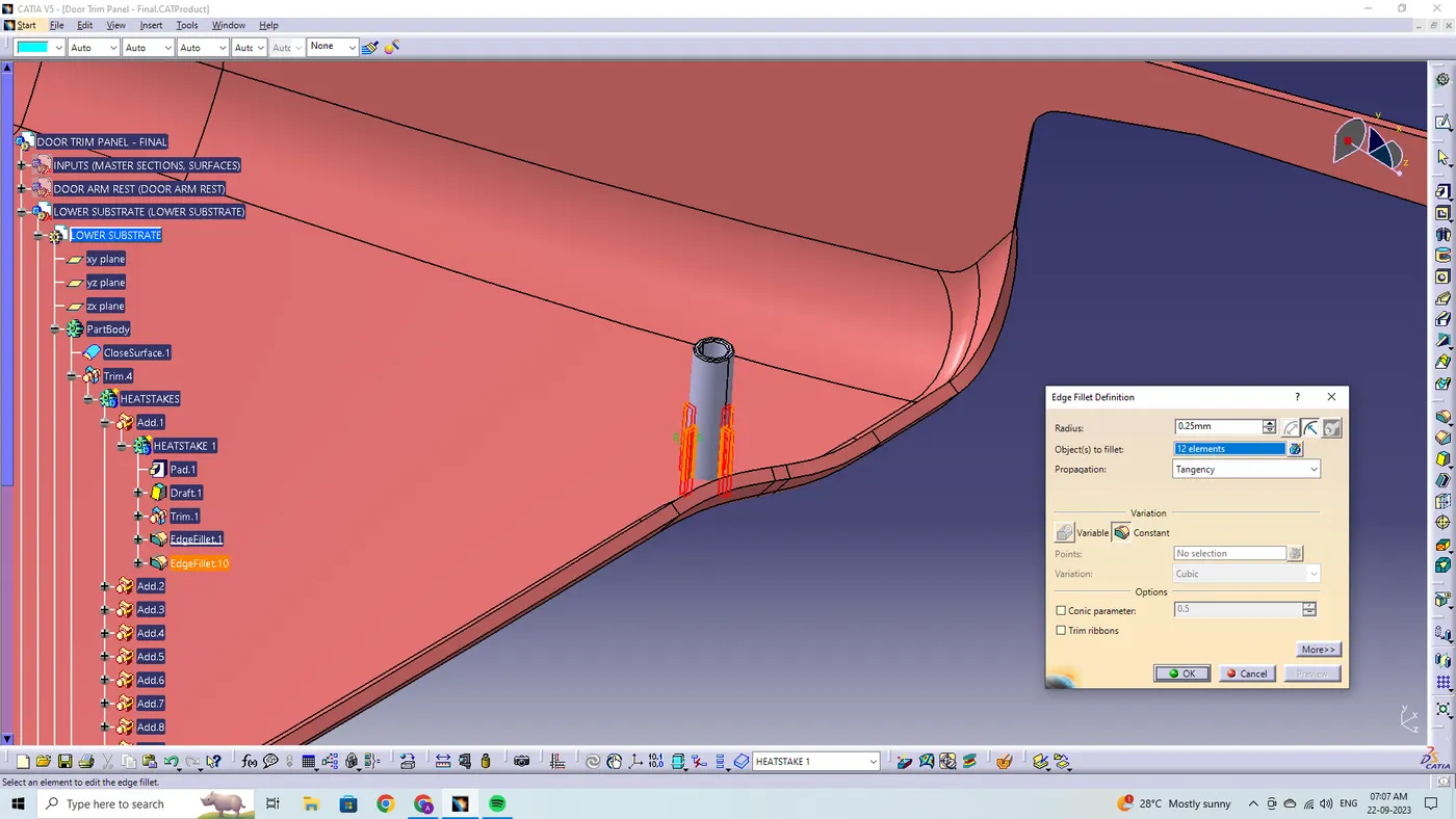
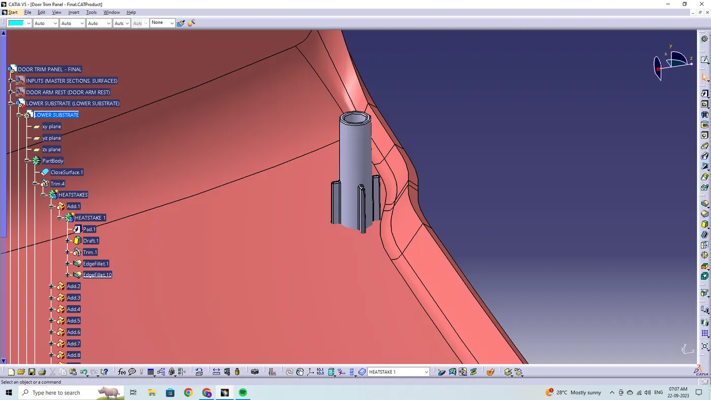
The boolean operation union trim is being performed on the created ribs and the faces to remove are being selected and the screw bosses with the supporting ribs are being formed in the solid part on the class B surface.
By using the parallel curve definition, the edges are being extracted and parallel curves are being created at the respective distance from the origin curve.
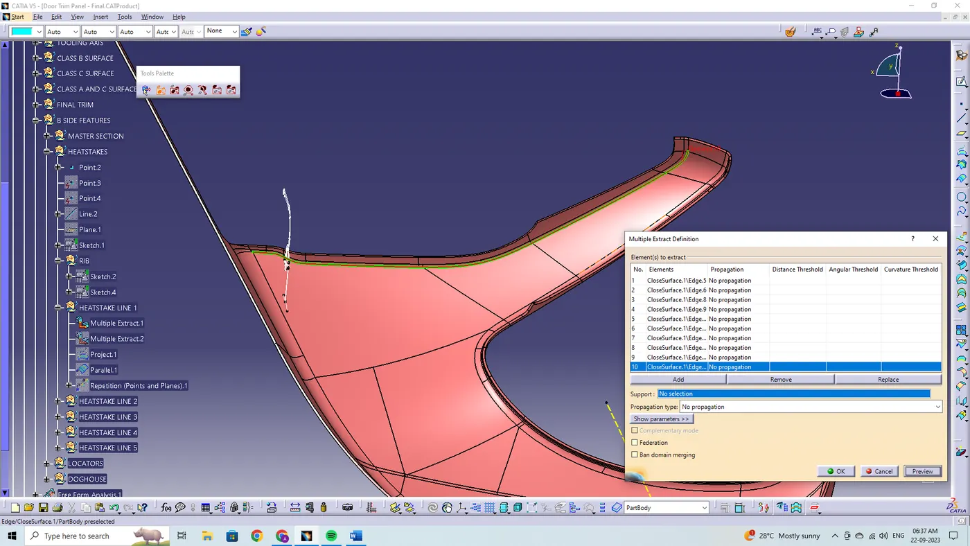
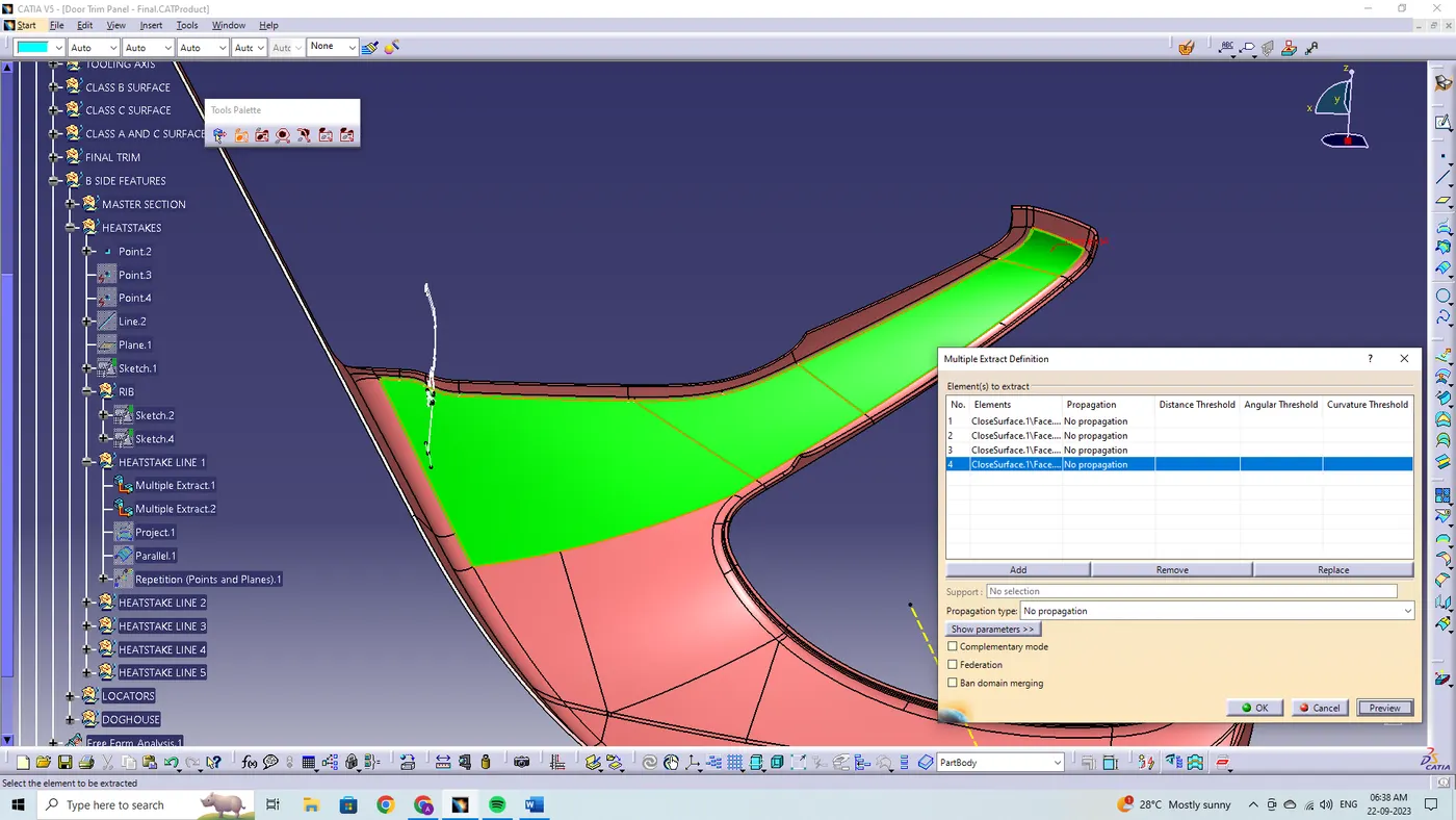
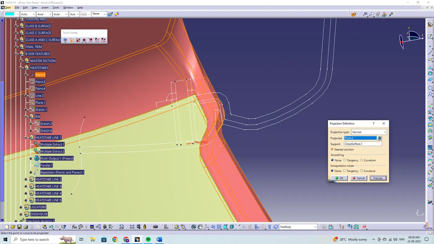
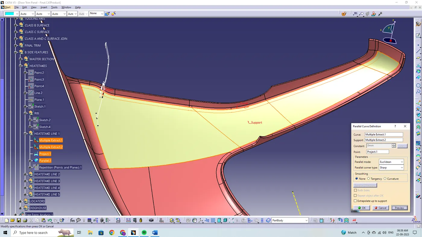
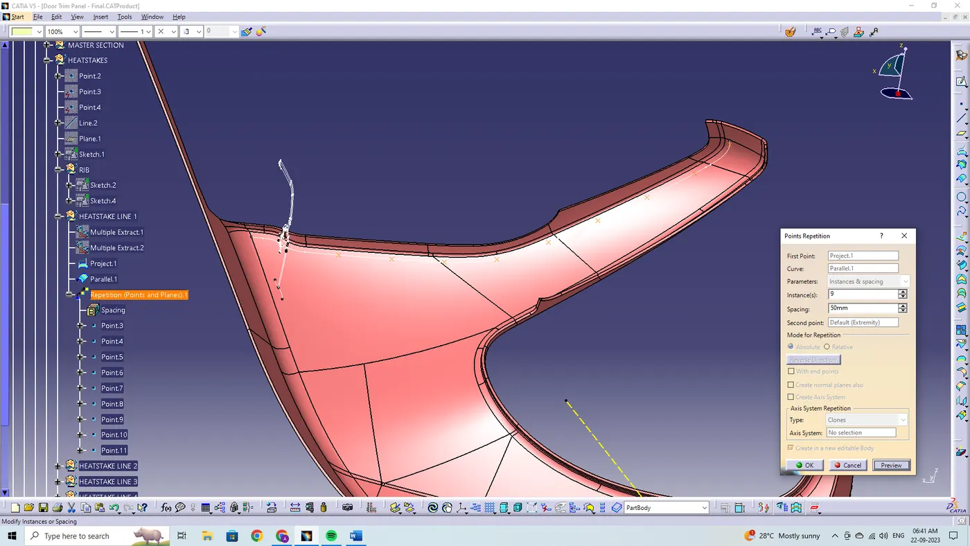
The heat stakes with the supporting rib profiles are being selected and using the translate feature another heat stakes are being created to the respective lengths.
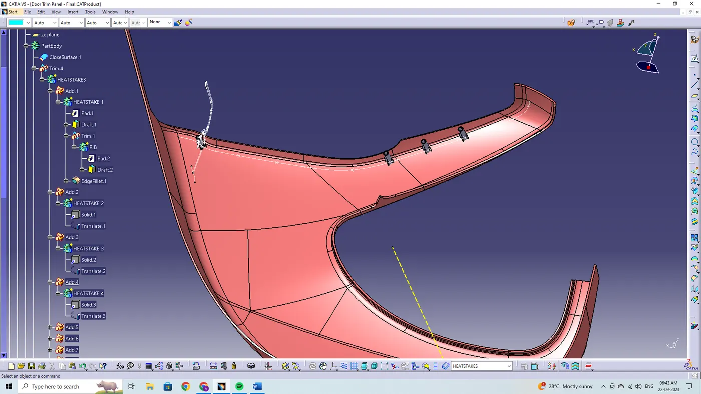
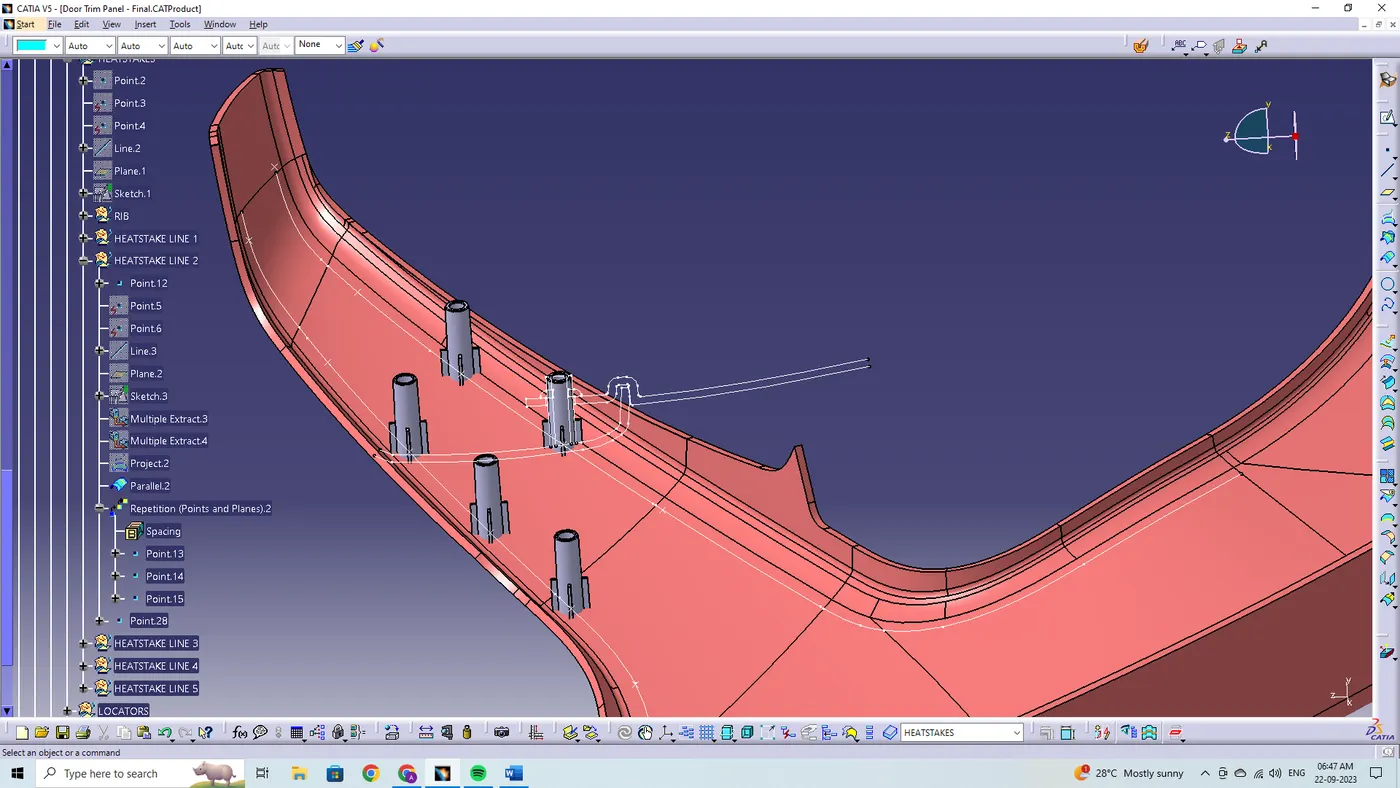
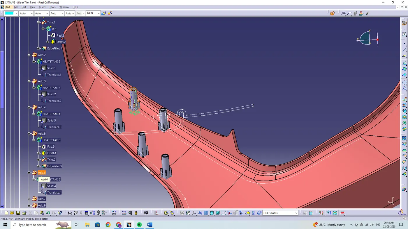
Likewise, the same procedure should be followed to create other heat stakes wherever you wish to place it.
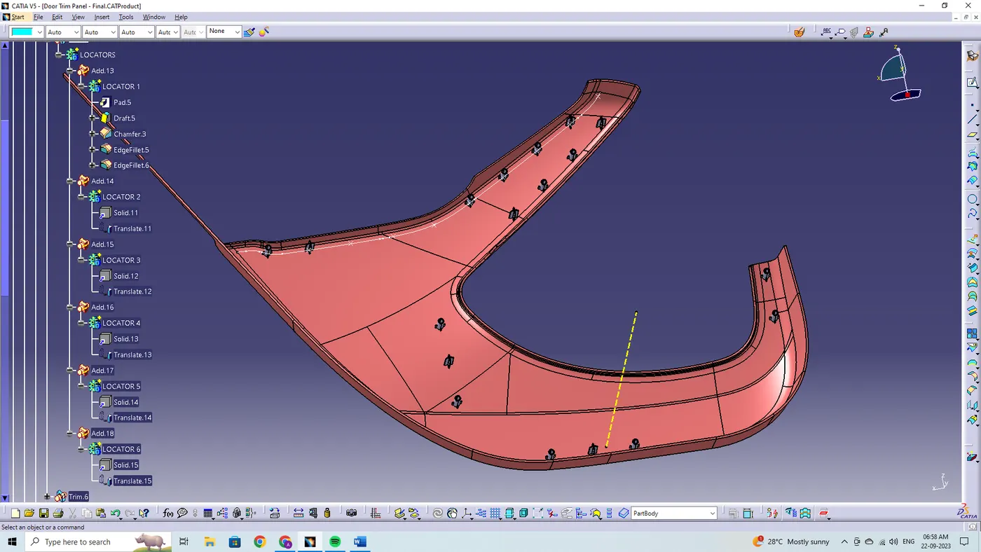
CREATING 4 WAY & 2 WAY LOCATORS ON CLASS "B" SURFACE:
CALCULATION FOR THE RIB DESIGN:
Create the 2-way/4-way locators for the considering the design rules mentioned in the video.
- Draft - 0.5 degrees on the walls of rib
- Thickness - Typically 40%* of the nominal wall thickness
- Height - ≤5 * wall thickness
- Spacing - 3:1 - (Steel) Height/Weight ratio
- Minimum thickness at the tip - 0.75mm
- Radii - 0.25mm maximum radii.
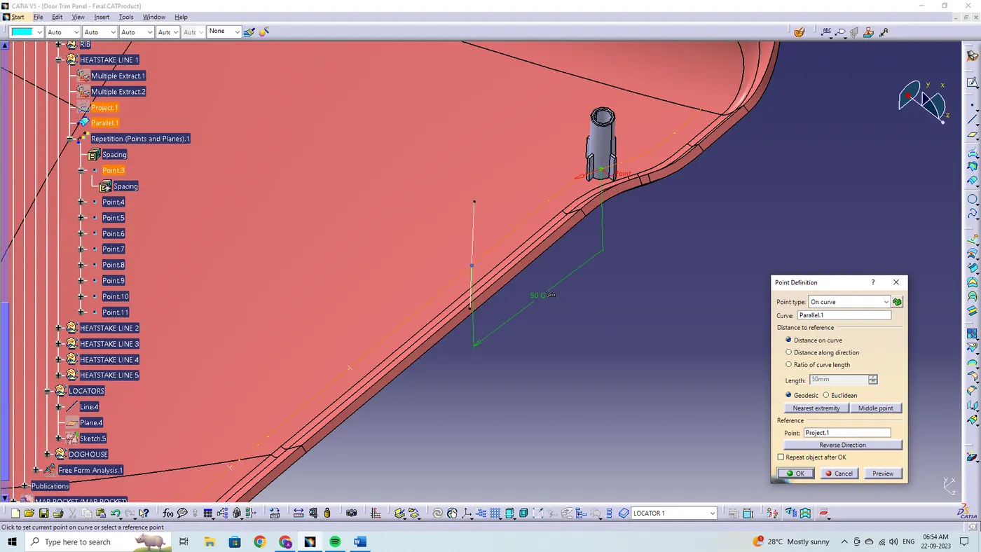
By using the point definition feature the point is created with the already created parallel curve as the curve option with a distance of 50mm.
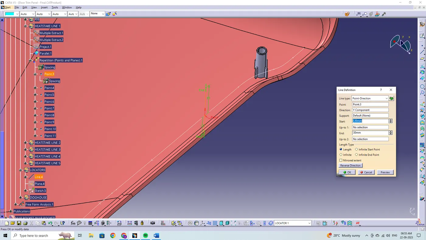
A line has been created using the line definition feature. From the line type point direction, points have been selected and direction along X component are selected to define the line.
By using the plane definition feature the respective planes are being created at the point reference.
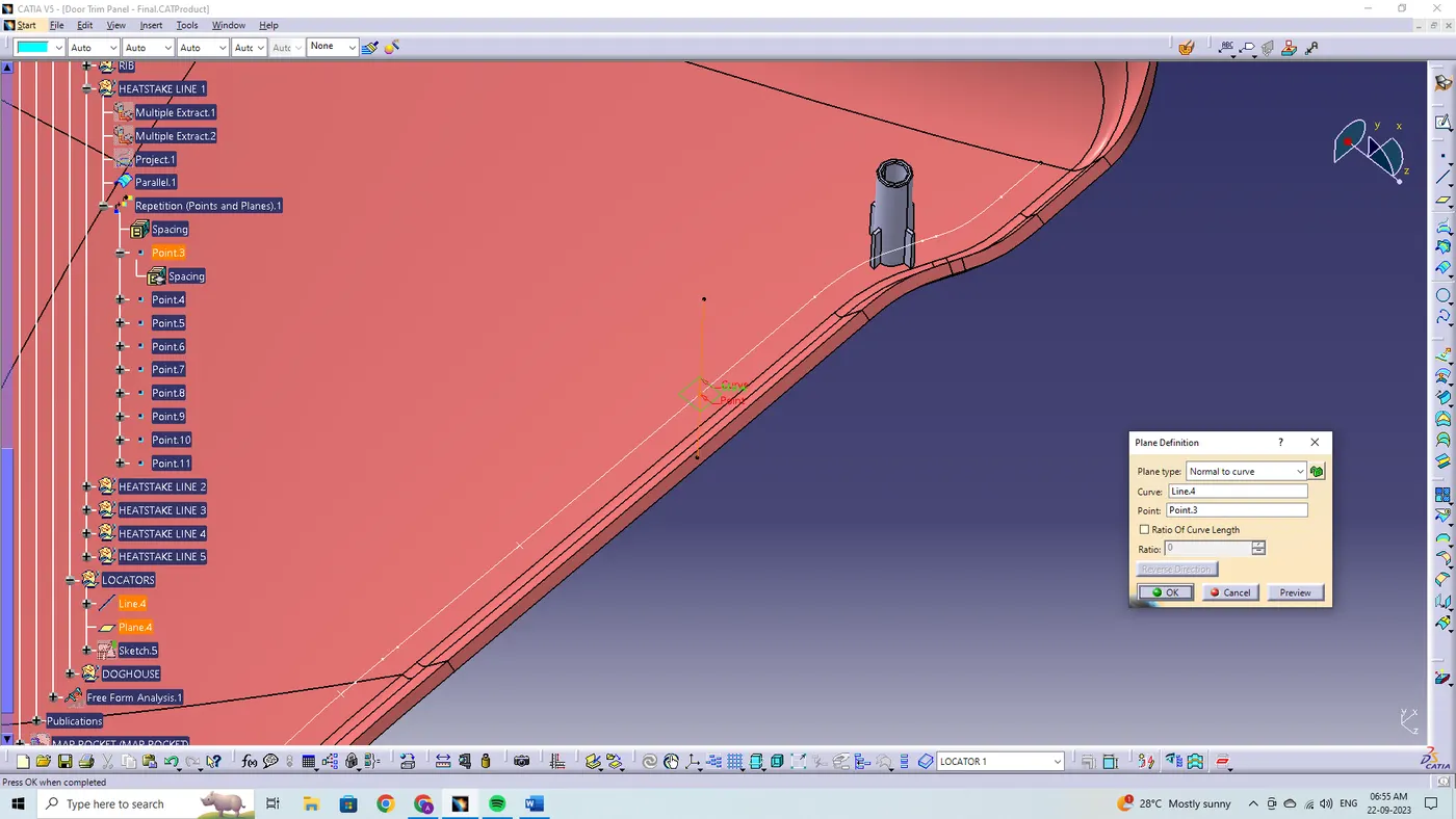
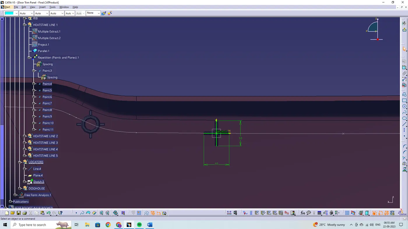
By using the positioned sketch, the point and plane are being selected and the locator lines are being drawn and the sketches are being iso-constrained using the respective geometrical and dimensional constraints.
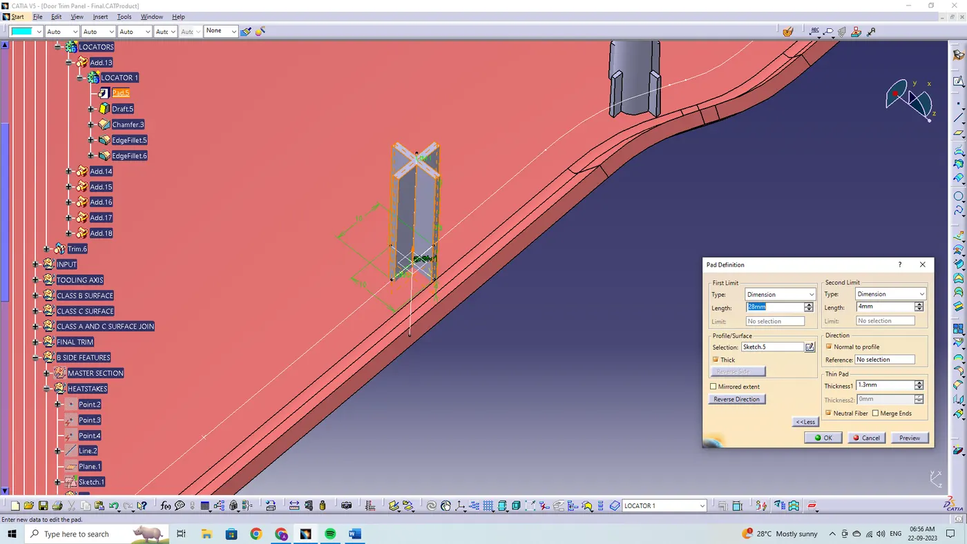
By using the pad definition, the 2-D sketches are being extruded to the thick and the first and second limit are being defined to the respective length to the respective direction.
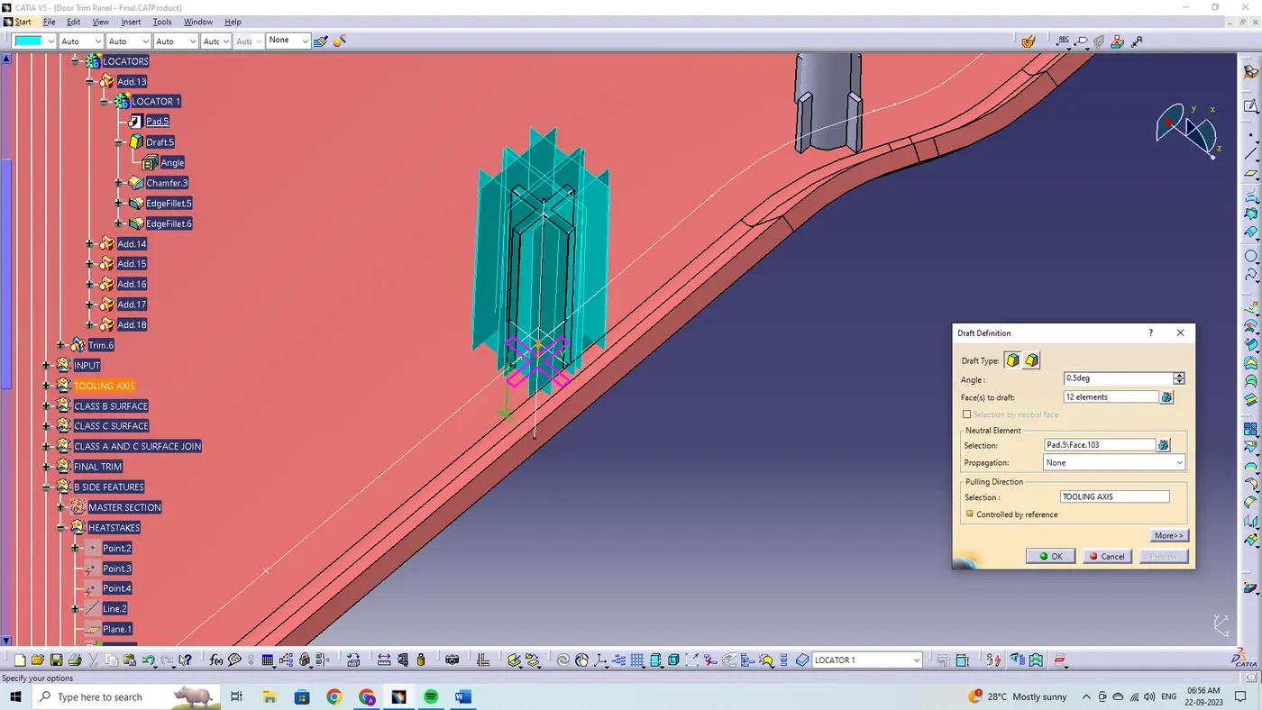
By using the draft definition, the faces are being selected to draft and the pulling direction are being selected as a main tooling axis also the neutral element to draft are being selected.
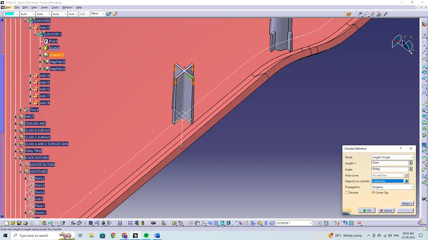
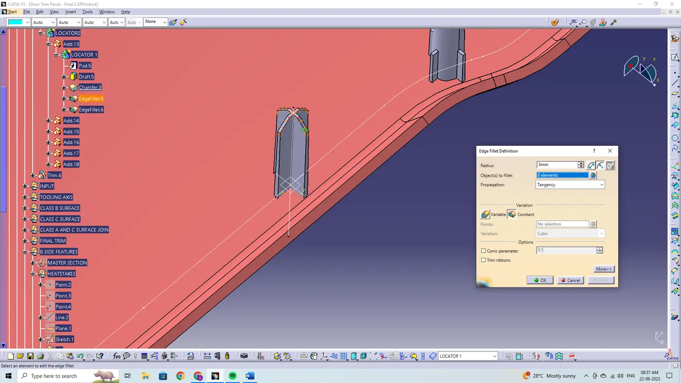
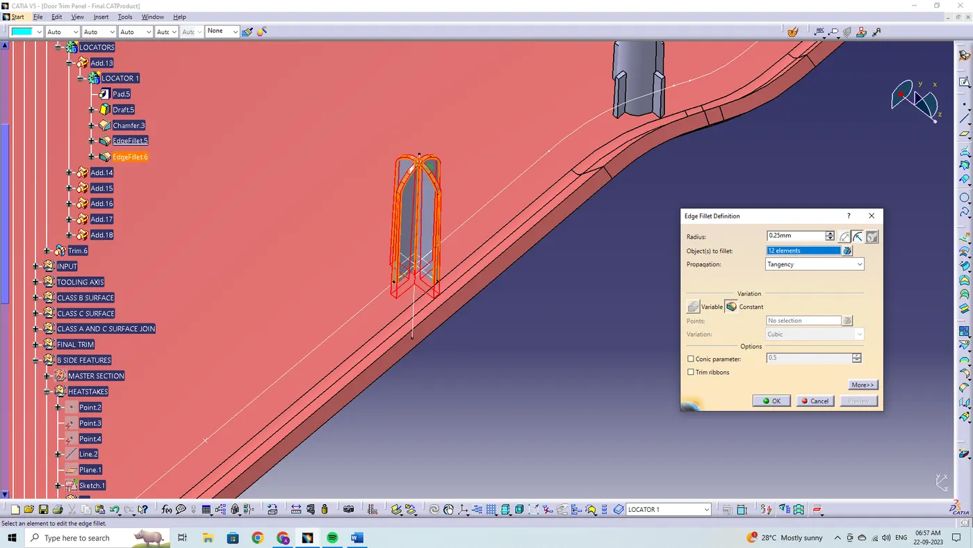
By using the chamfer and the edge fillet definition the respective values are provided as per the design rules at chamfer 3mm and fillet radius 3mm and 0.25mm and by using the Boolean operation union trim the locators are being trimmed by selecting the remove faces and added with the main part body.
DRAFT ANALYSIS:
The draft analysis has been performed on the final component created as a closed body using the part design closed surface feature. For plastic components the minimum angle required for the draft to be 3 degrees.
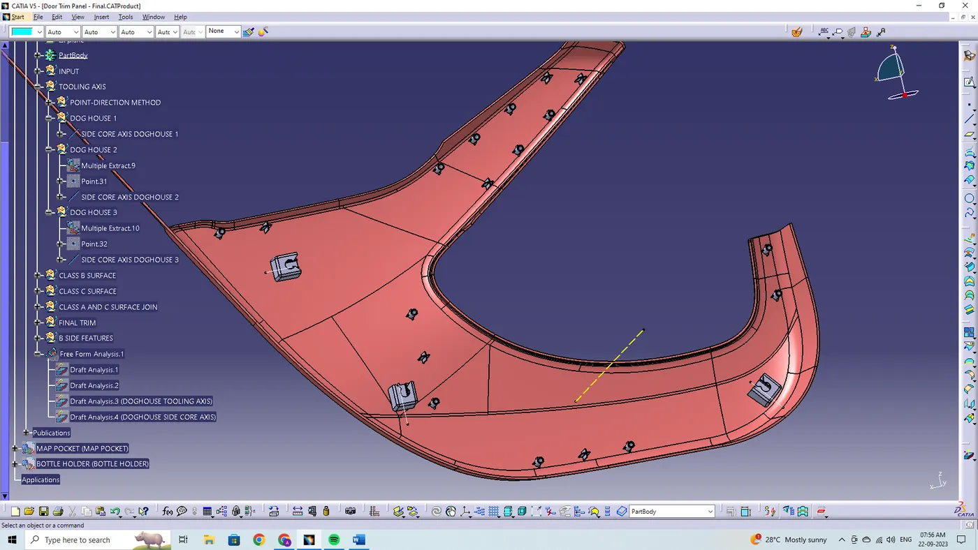
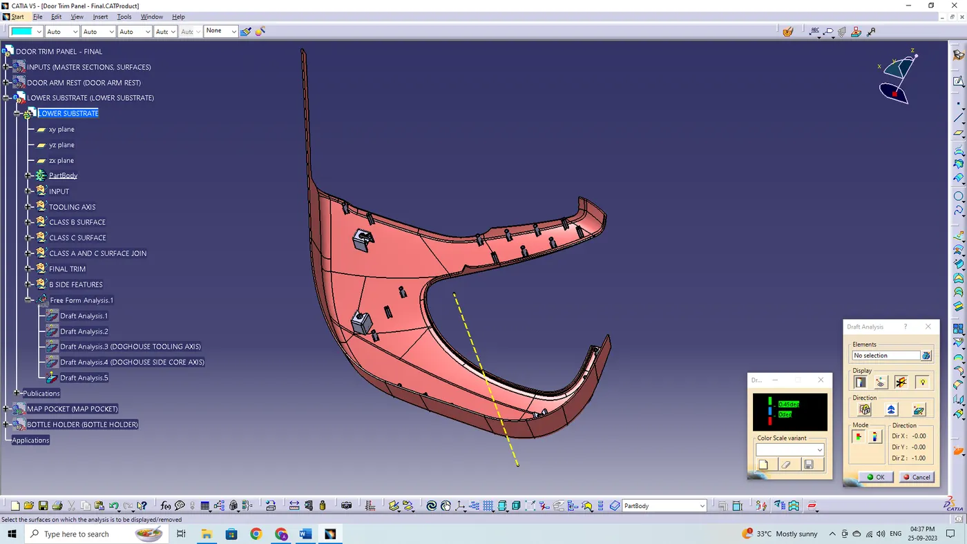
The direction compass is to be selected and placed on the main tooling axis line and the compass is being locked using the lock feature in the direction.
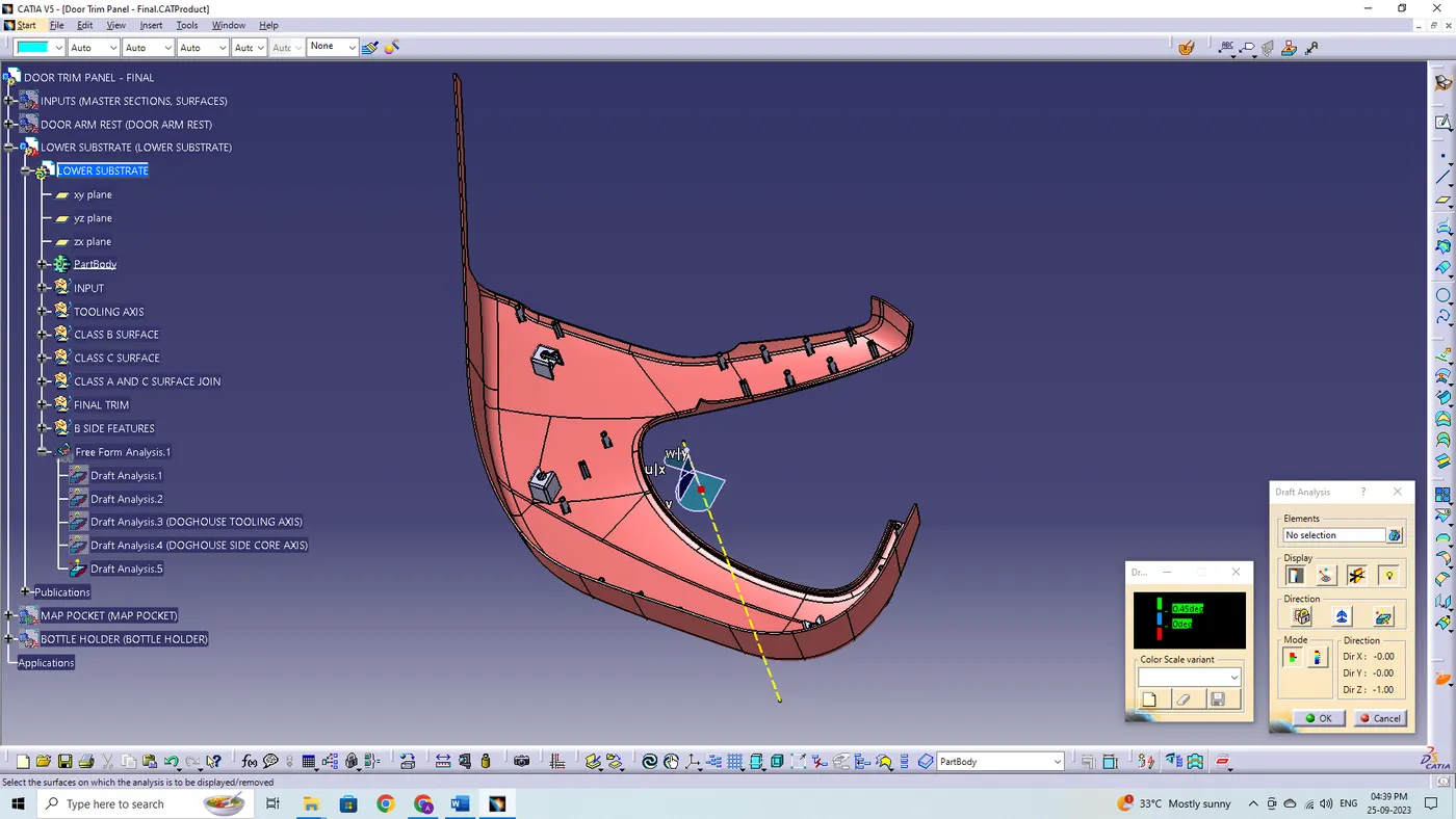
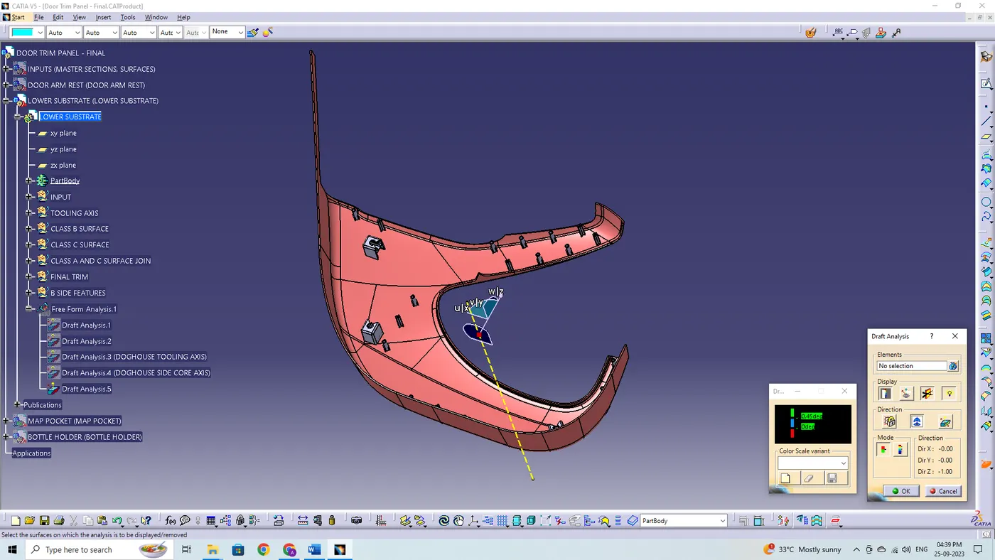
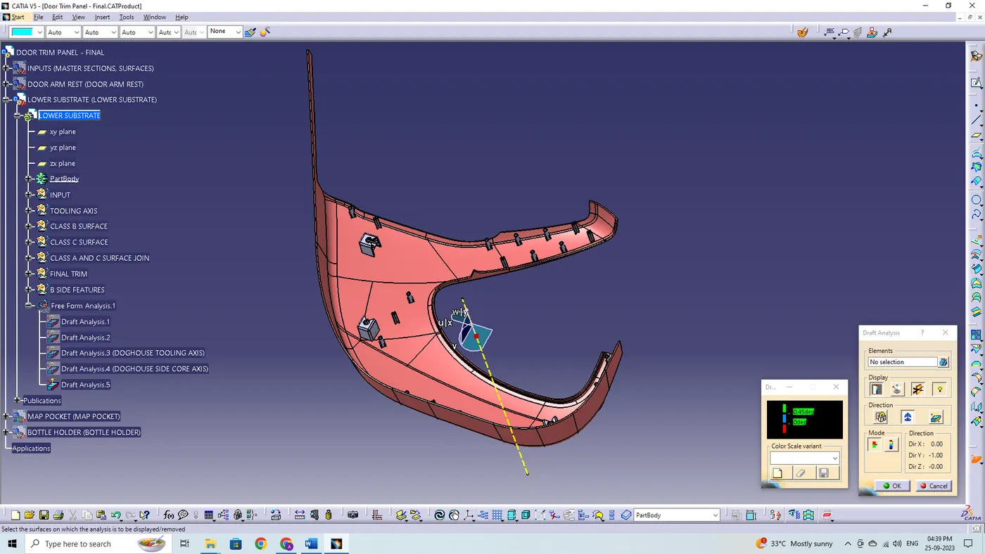
In the display window the colour code variants are being selected, to know the range of the draft in the class A surface. In the display window the colour variants show,
- For 3 degree - Green color variant (Positive)
- For 0 degree - Blue color variant
- For <0>
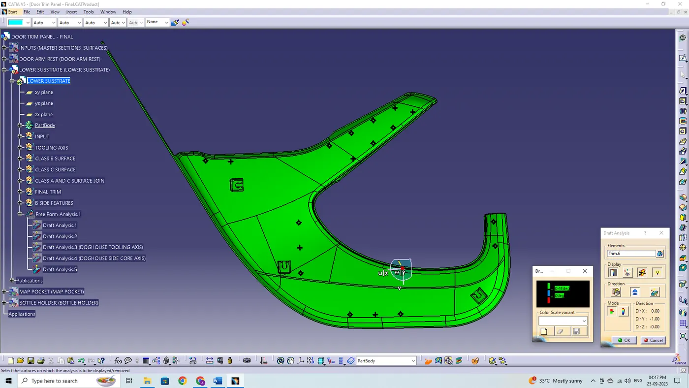
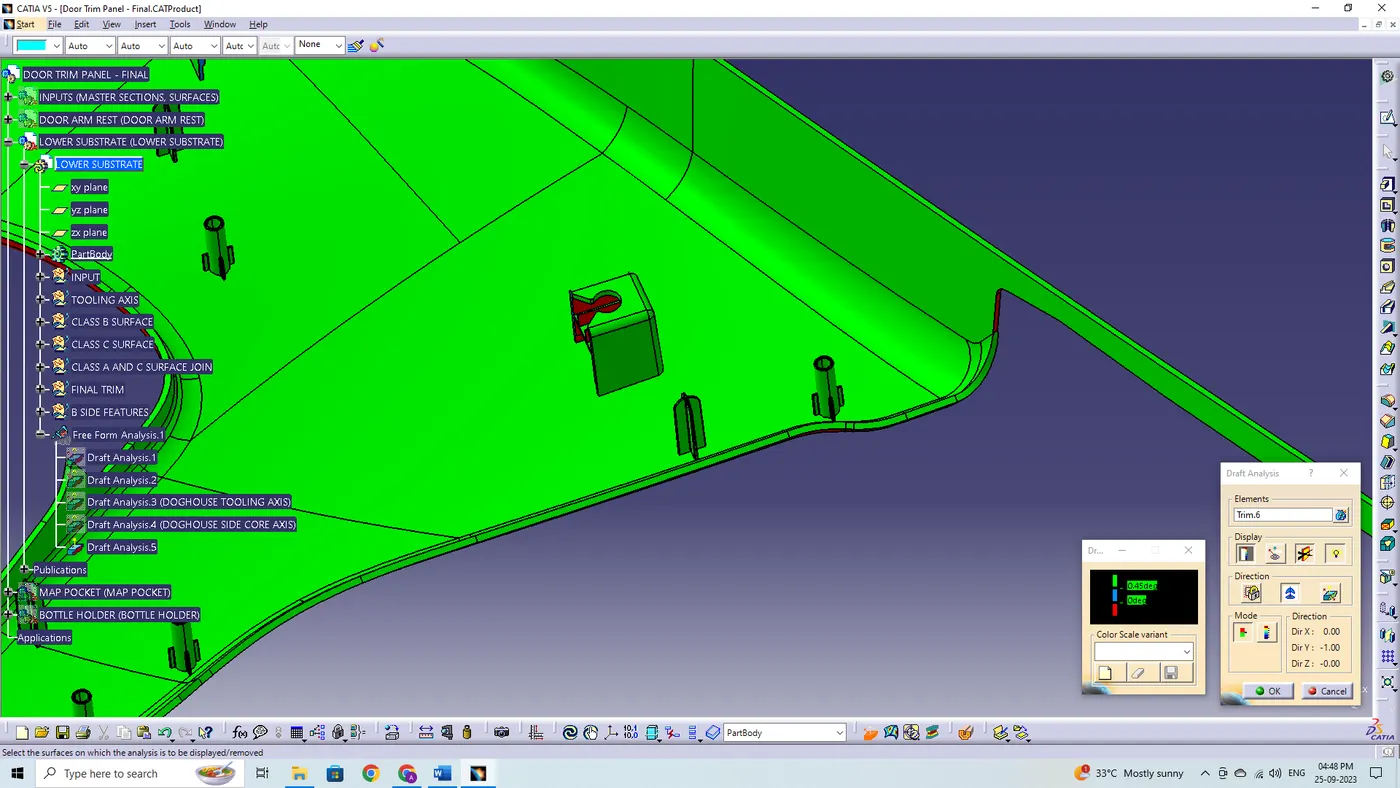
The draft analysis is being performed in both the core and cavity side of solid body. The green colour implies the draft angle are in the positive region. If the draft angle is being inverted the colour of the surface are implied as blue colour.
DOGHOUSE:
General Guidelines for Doghouse:
- Doghouse wall thickness at the intersection of the part wall (C) should be 40% or less than the main wall stock (T).
- "C" is where the doghouse contacts the backside of the surface.
- The height of (B) should be between 3.0 – 6.0 mm.
CONSTRUCTION OF DOGHOUSE:
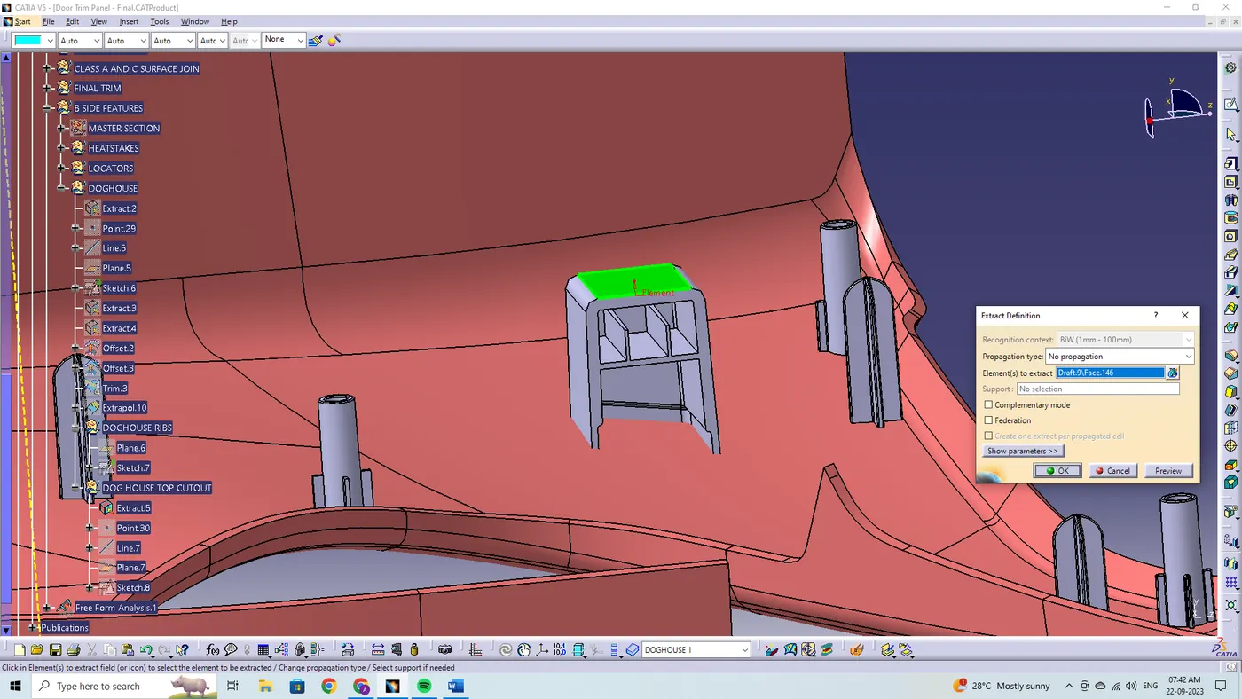
Here we take an extract of the surface from the lower substrate component for location and creation of the doghouse.
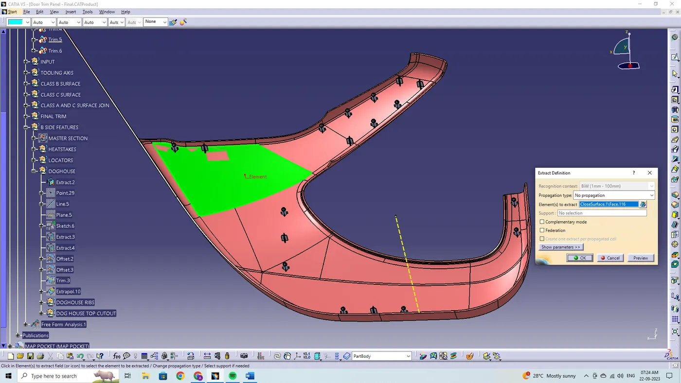
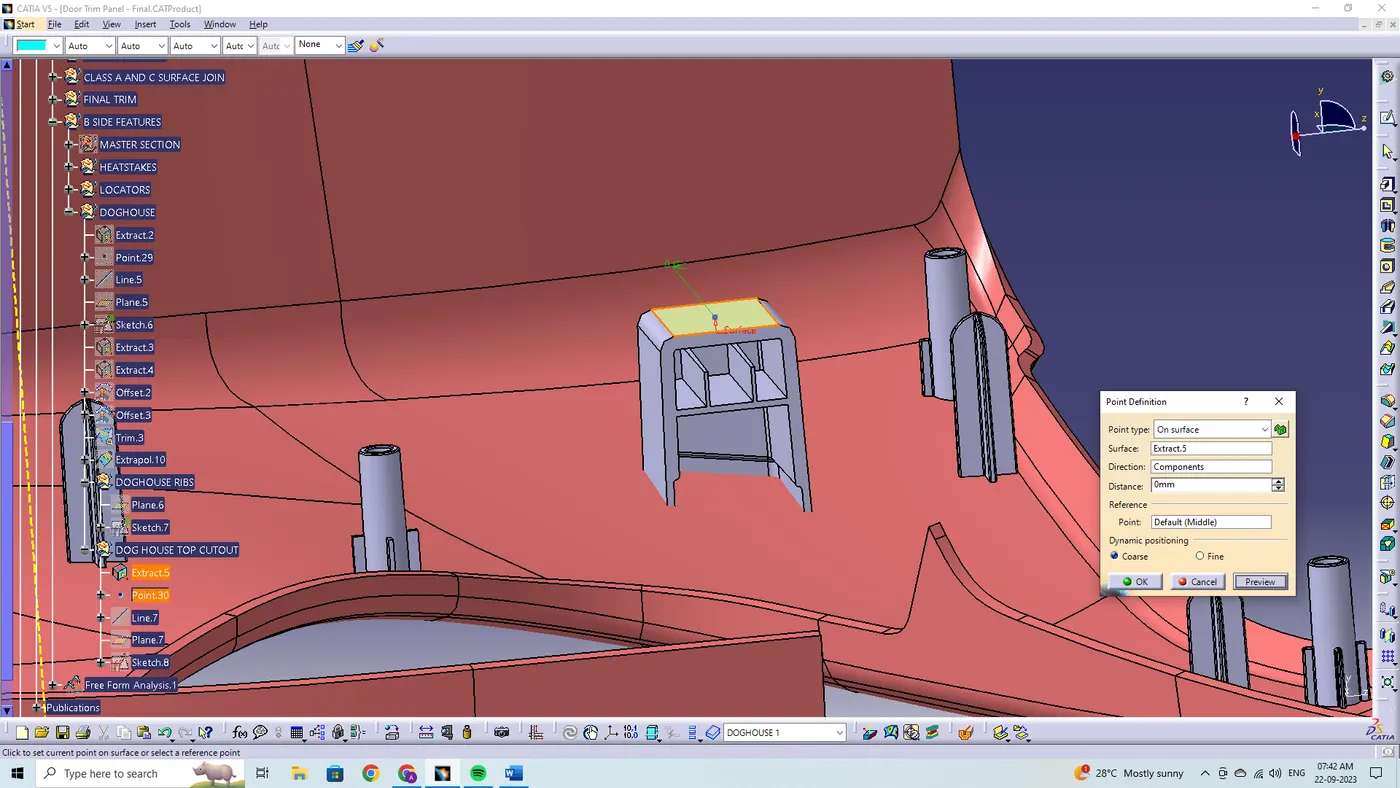
By using the point definition feature the point is created on the surface extracted with where you want, your doghouse to be.
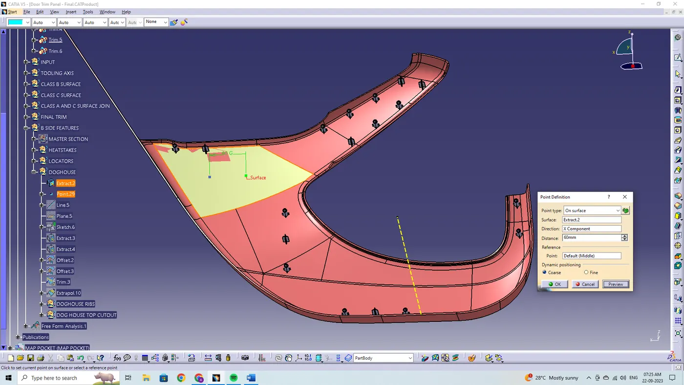
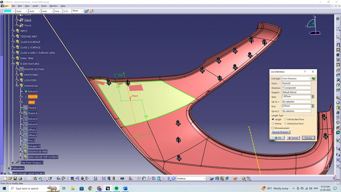
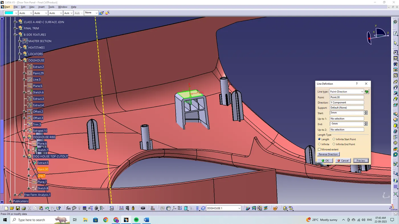
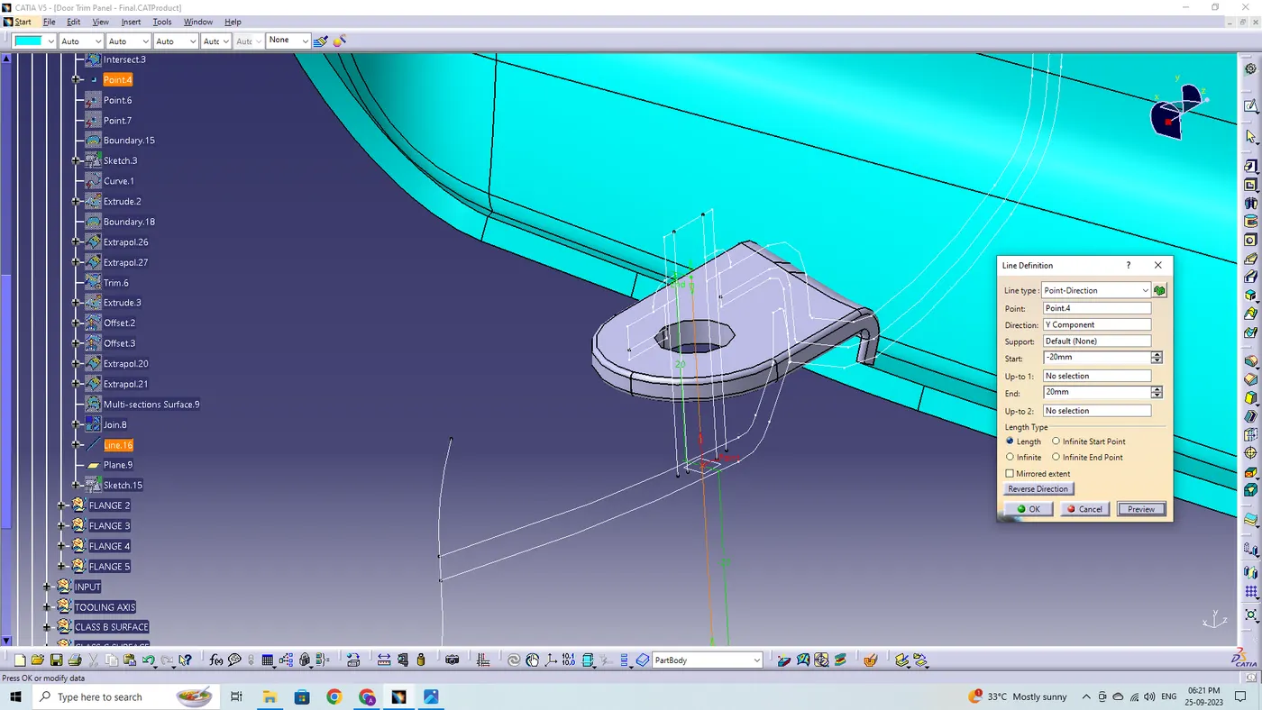
A line has been created using the line definition feature. From the line type point direction, points have been selected and direction along Y component are selected to define the line.
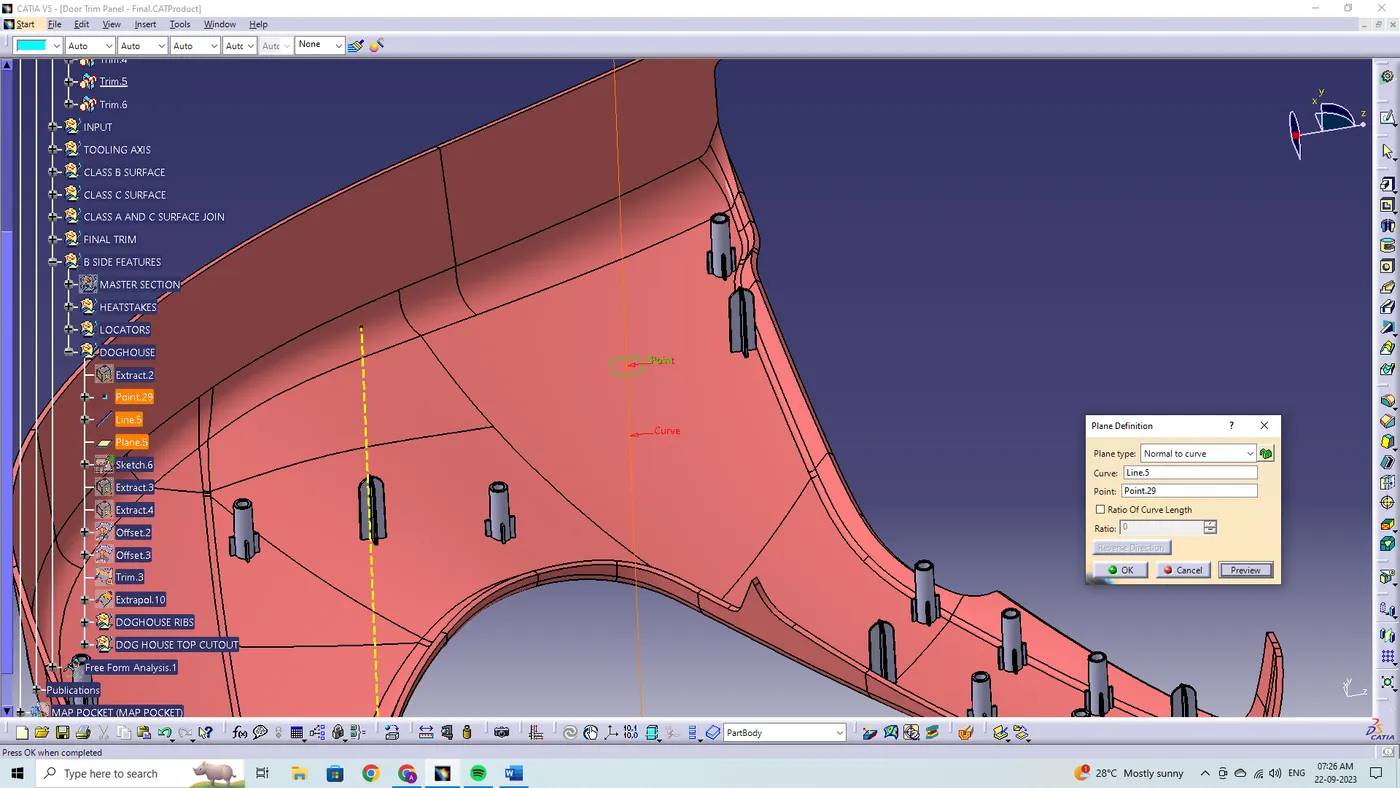
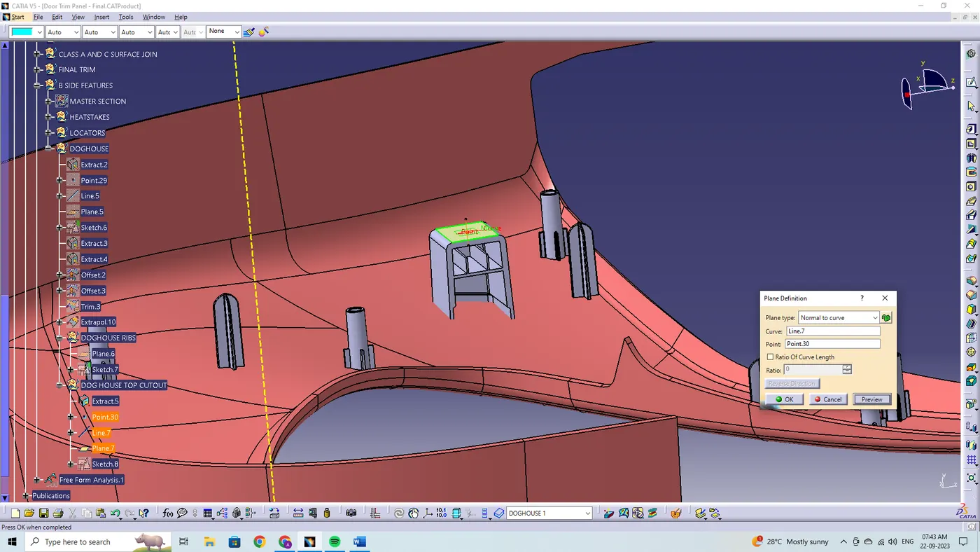
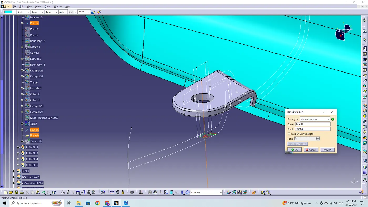
By using the plane definition feature the respective plane is being created at the point reference.
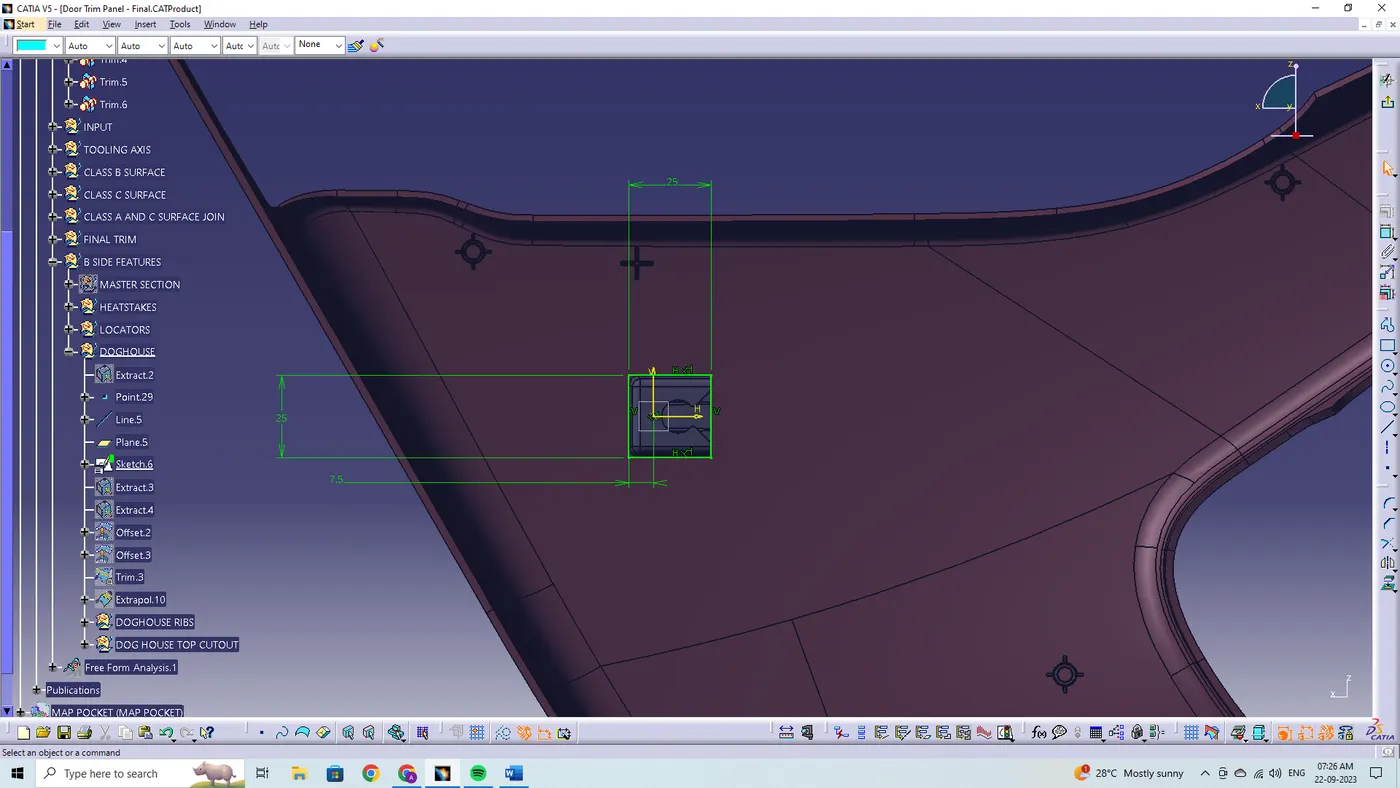
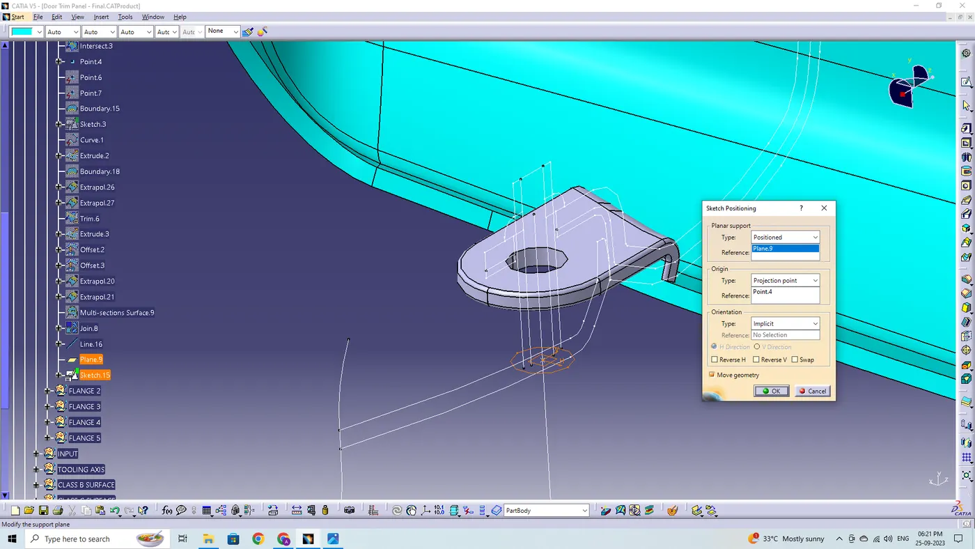
By using the plane and the projection point, positioned sketches are being created to sketch the profile of the doghouse with respective design rules.
By using the pad definition, the 2-D sketches are being extruded to the thick and the first and second limit are being defined to the respective length to the respective direction.
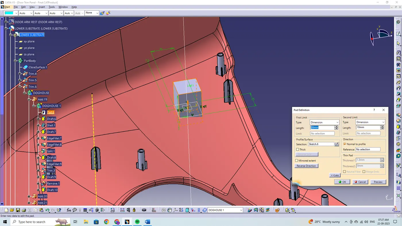
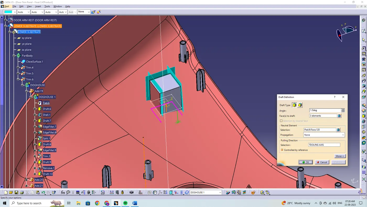
By using the draft definition, the faces are being selected to draft and the pulling direction are being selected as a main tooling axis also the neutral element to draft are being selected.
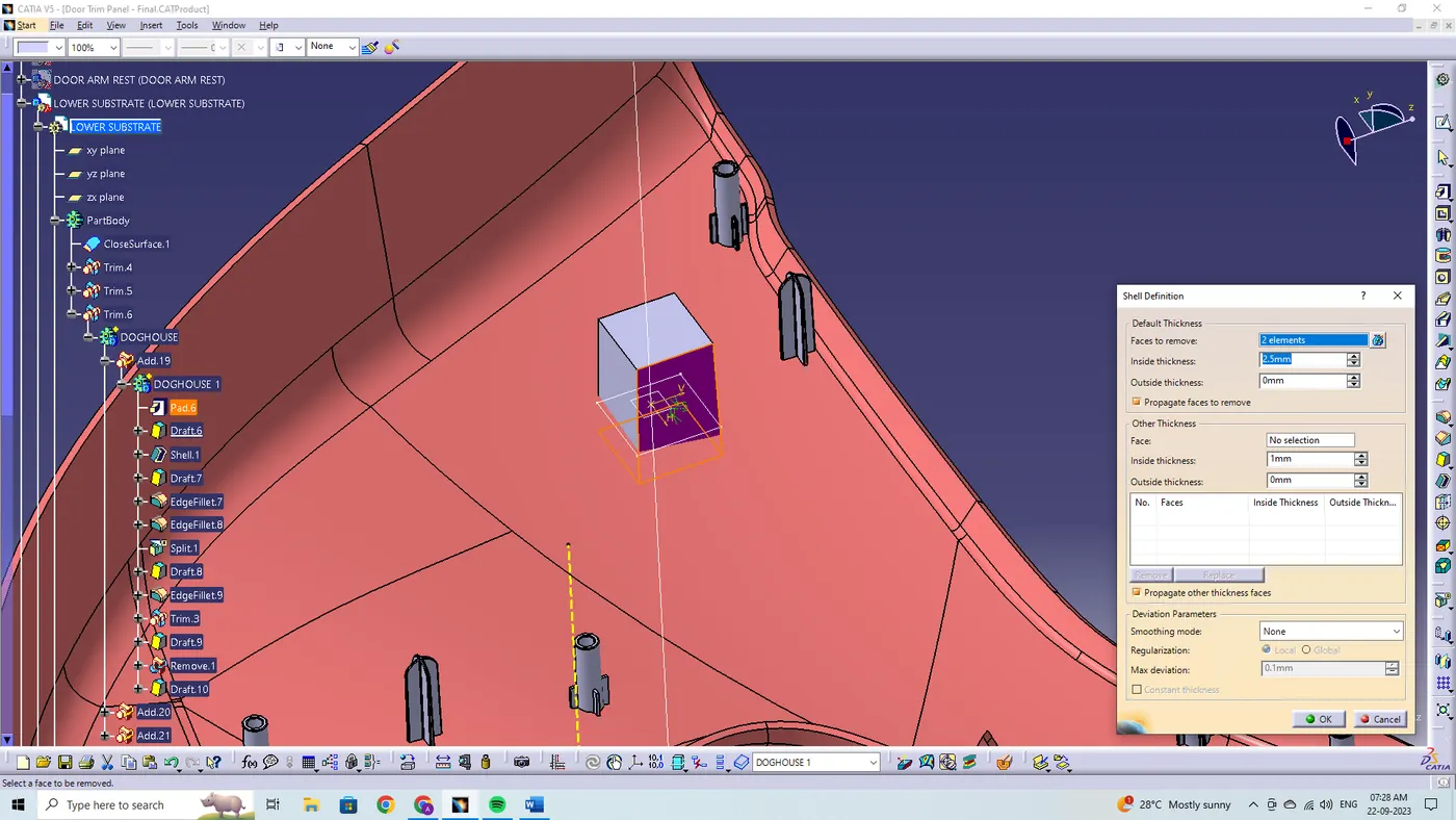
By using the shell definition, we get remove the unwanted material from the whole block to the required thickness.
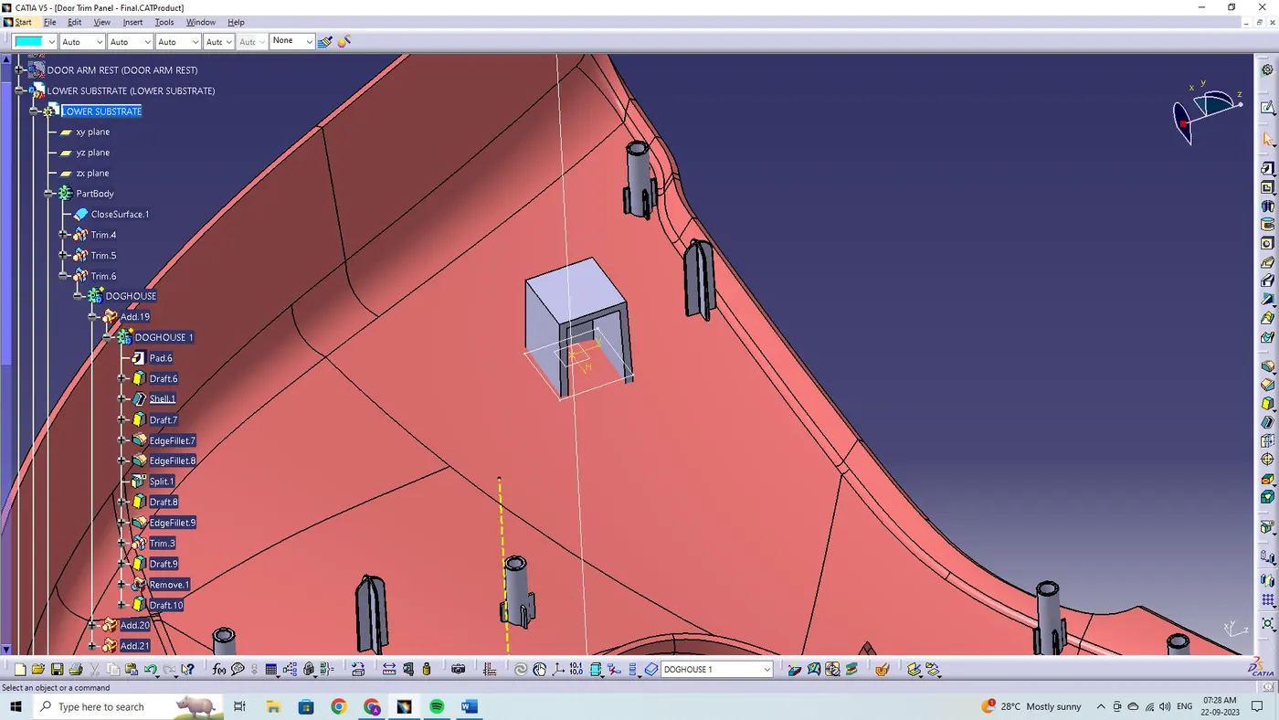
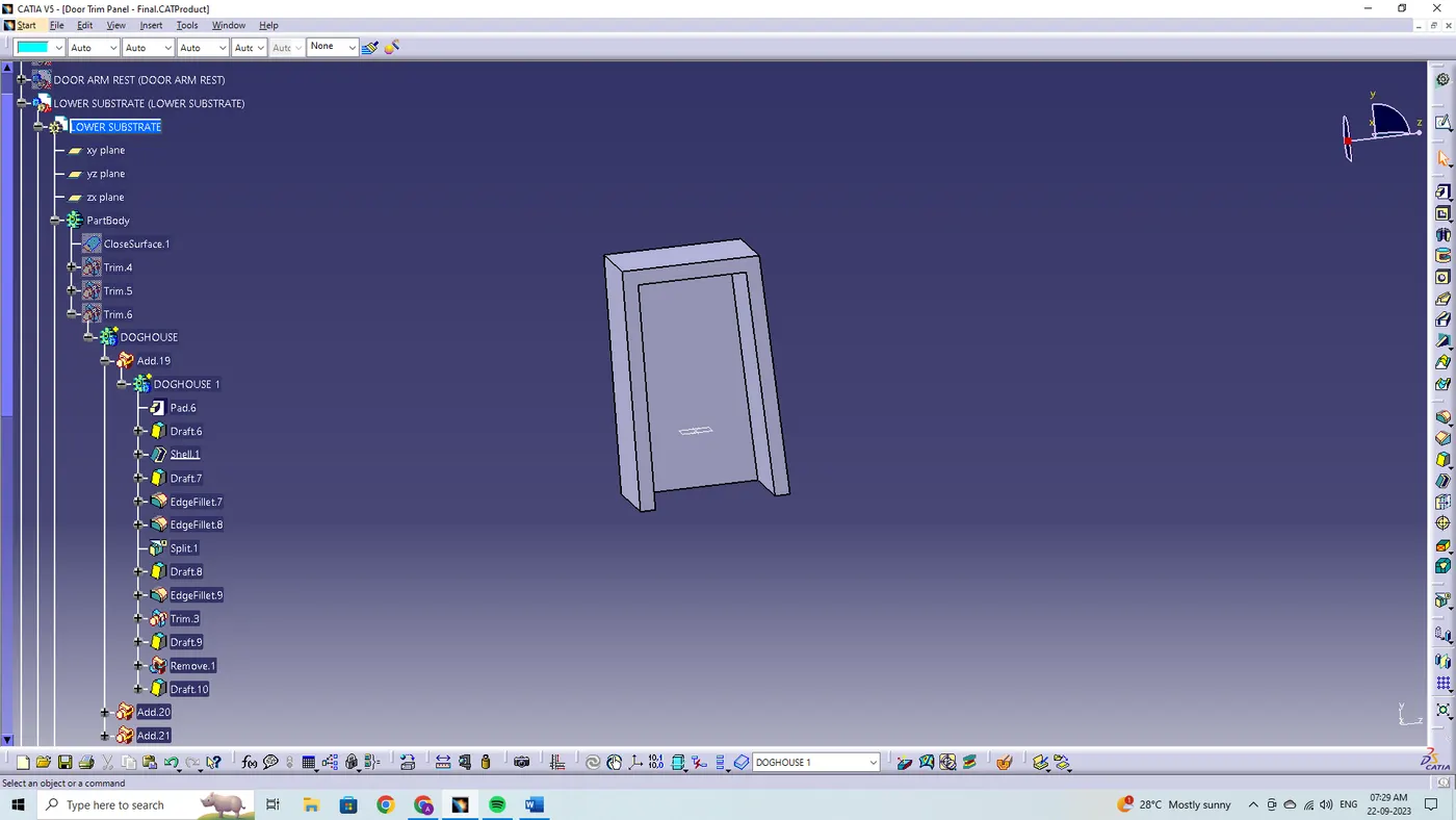
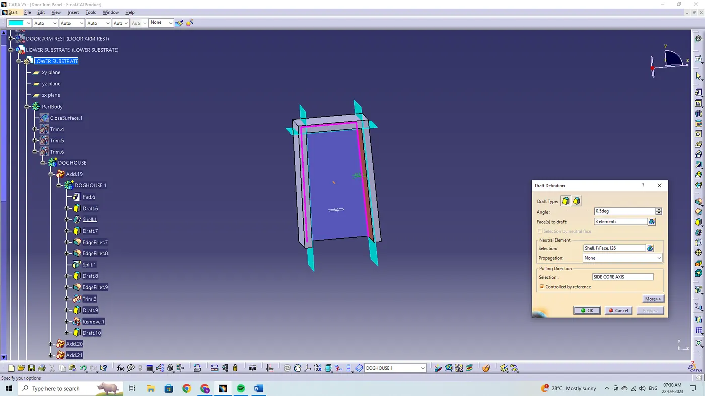
By using the draft definition, the faces are being selected to draft and the pulling direction are being selected as a main tooling axis also the neutral element to draft are being selected.
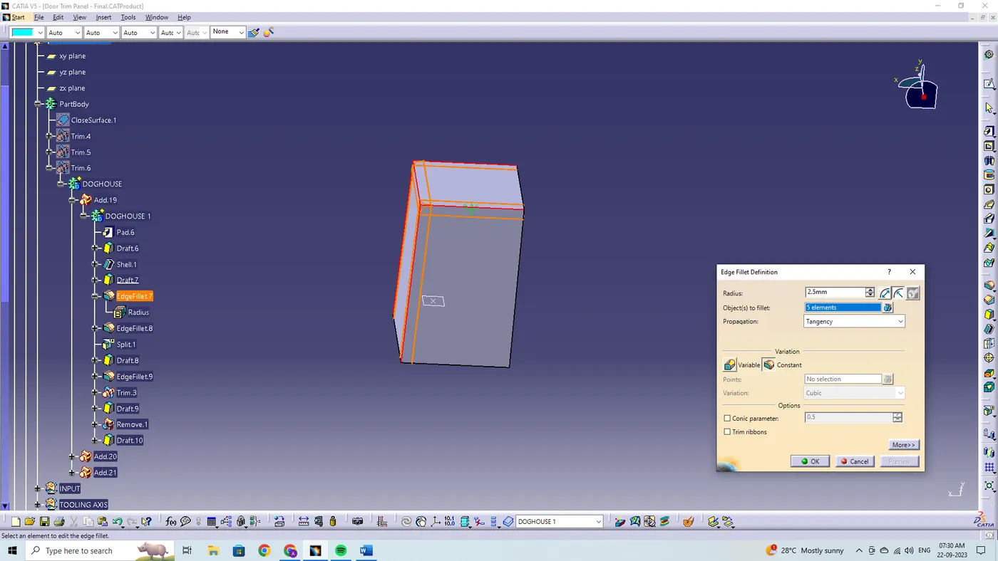
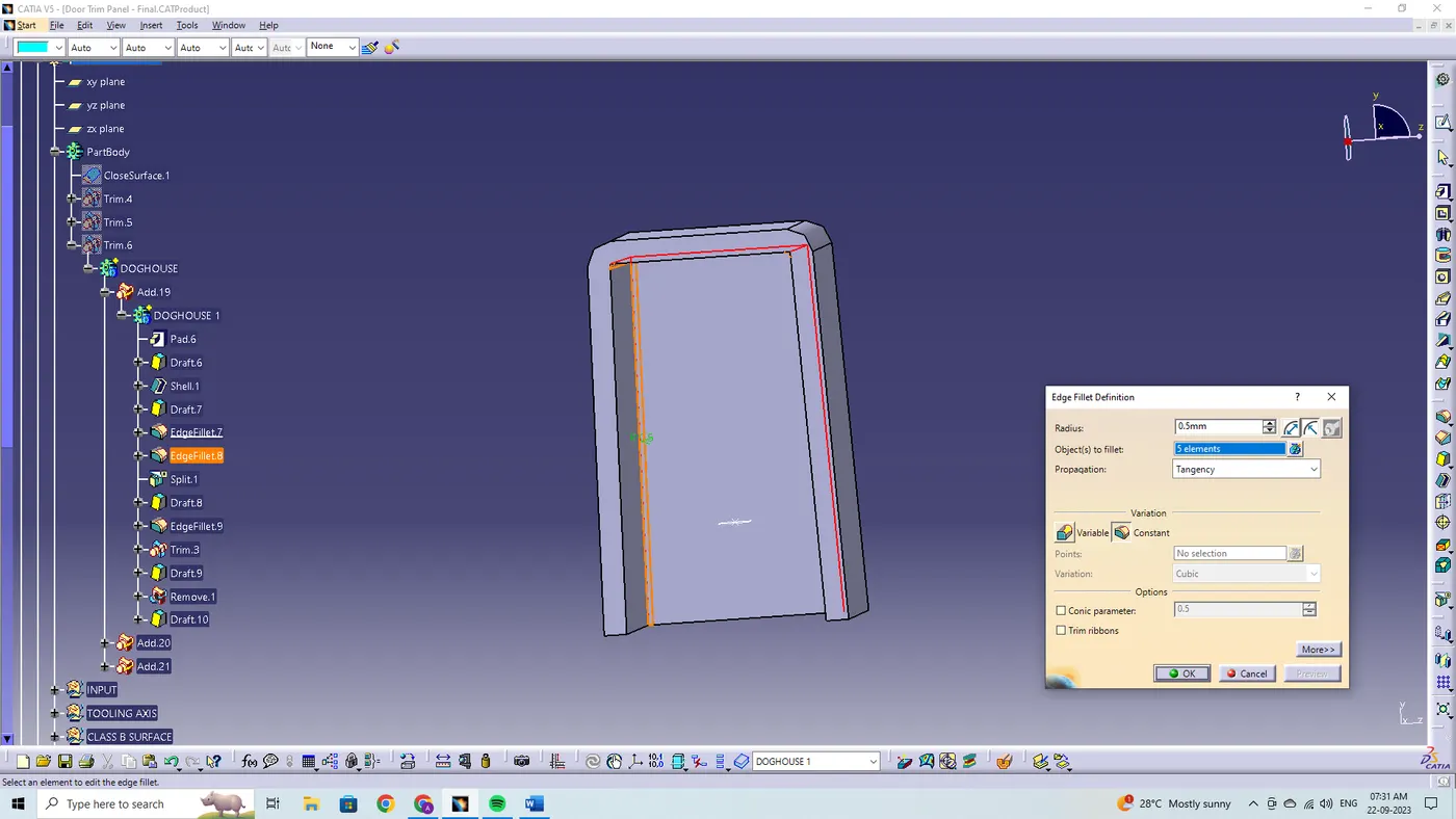
By using the edge fillet definition, the respective values are provided as per the design rules at fillet radius 2.5 mm for the outer doghouse and 0.5mm for inner side of the doghouse.
Here, we extract the inner side of the doghouse, and we also extract the surface of the lower substrate to create another base wall for the doghouse.
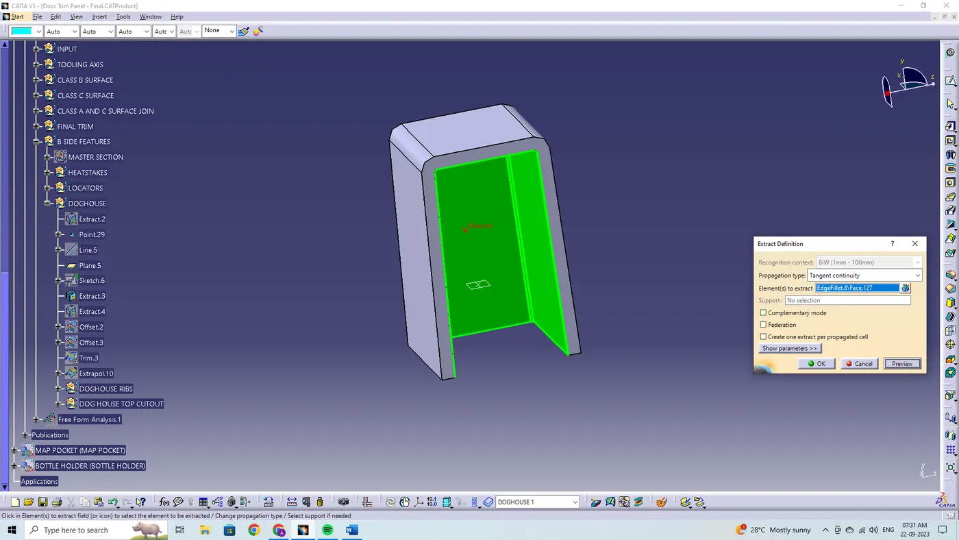
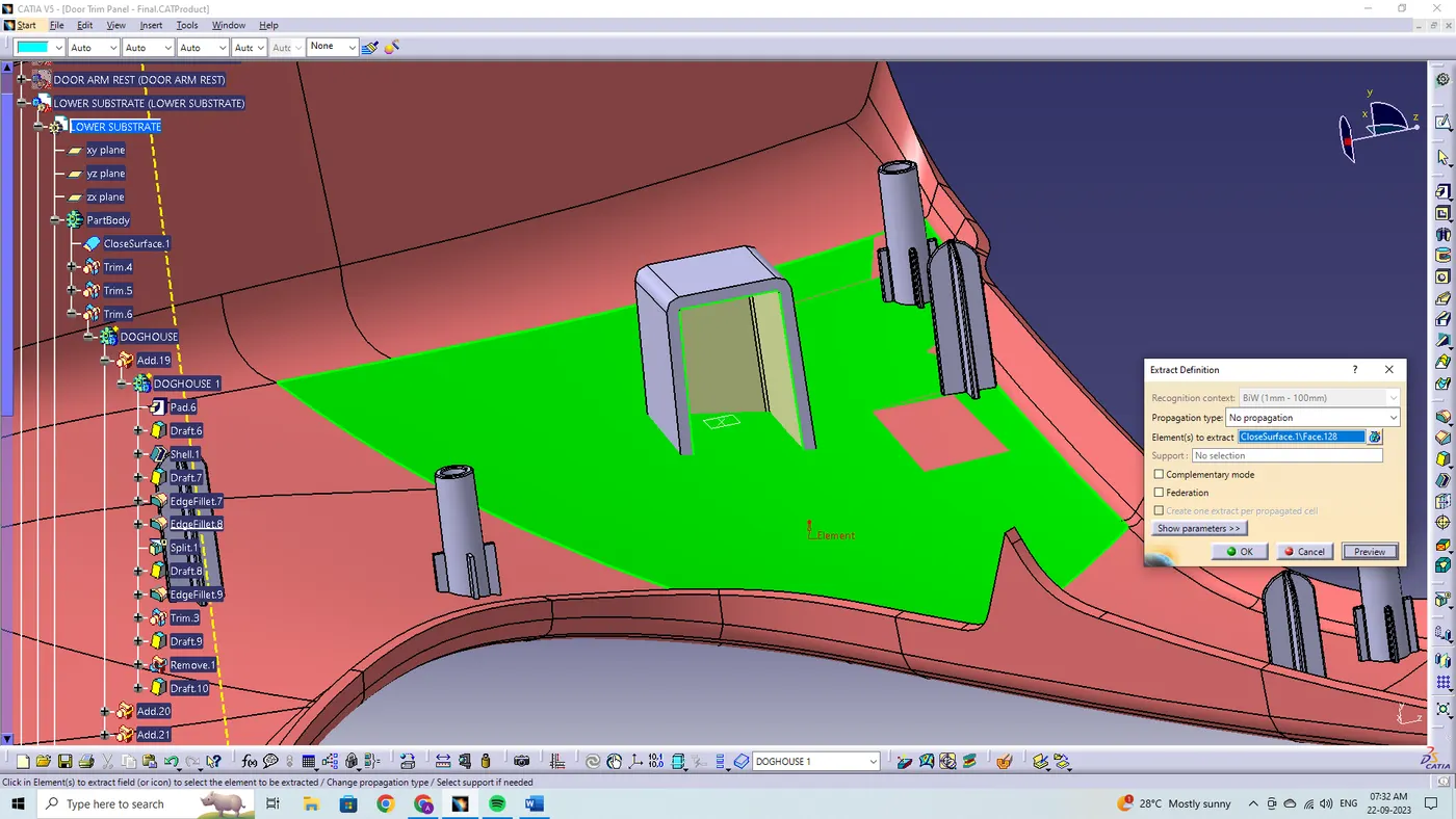
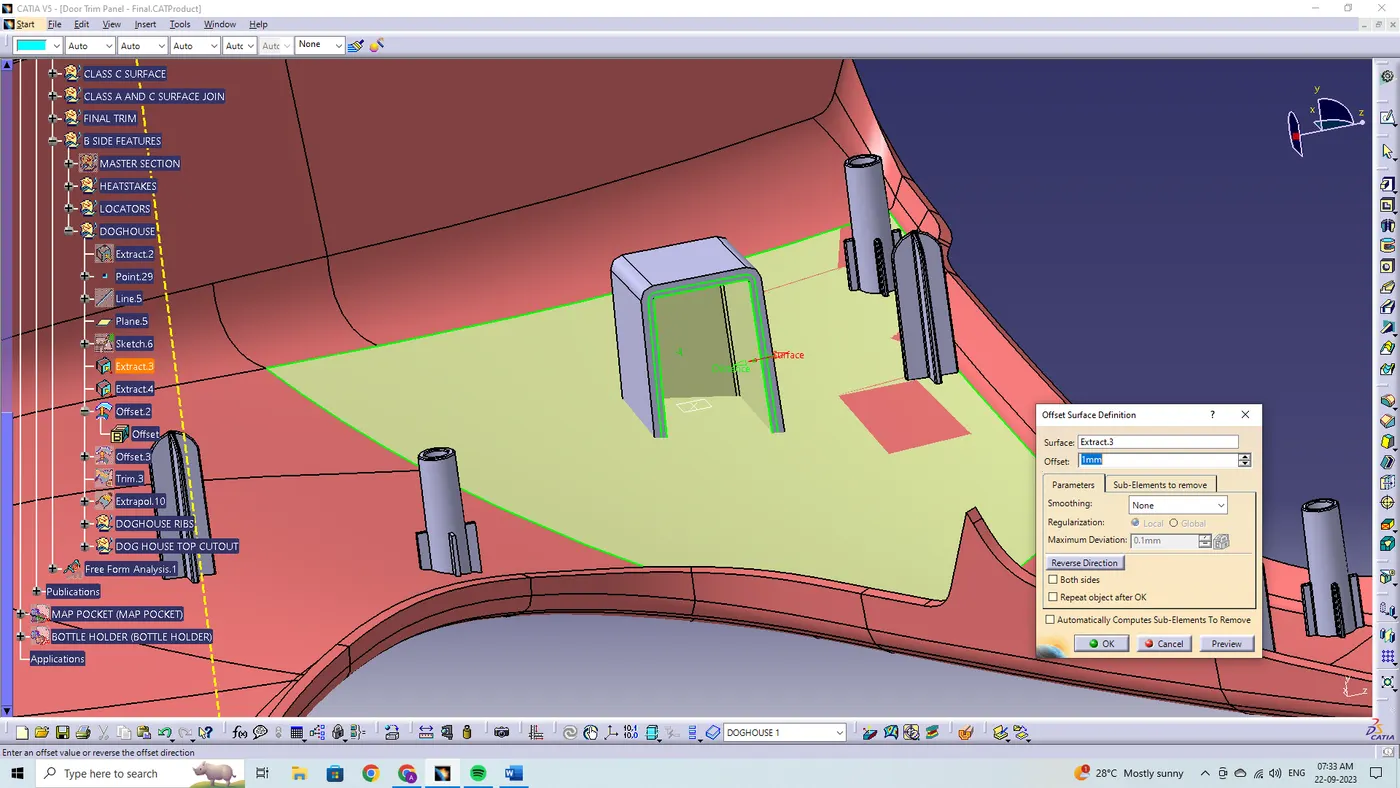
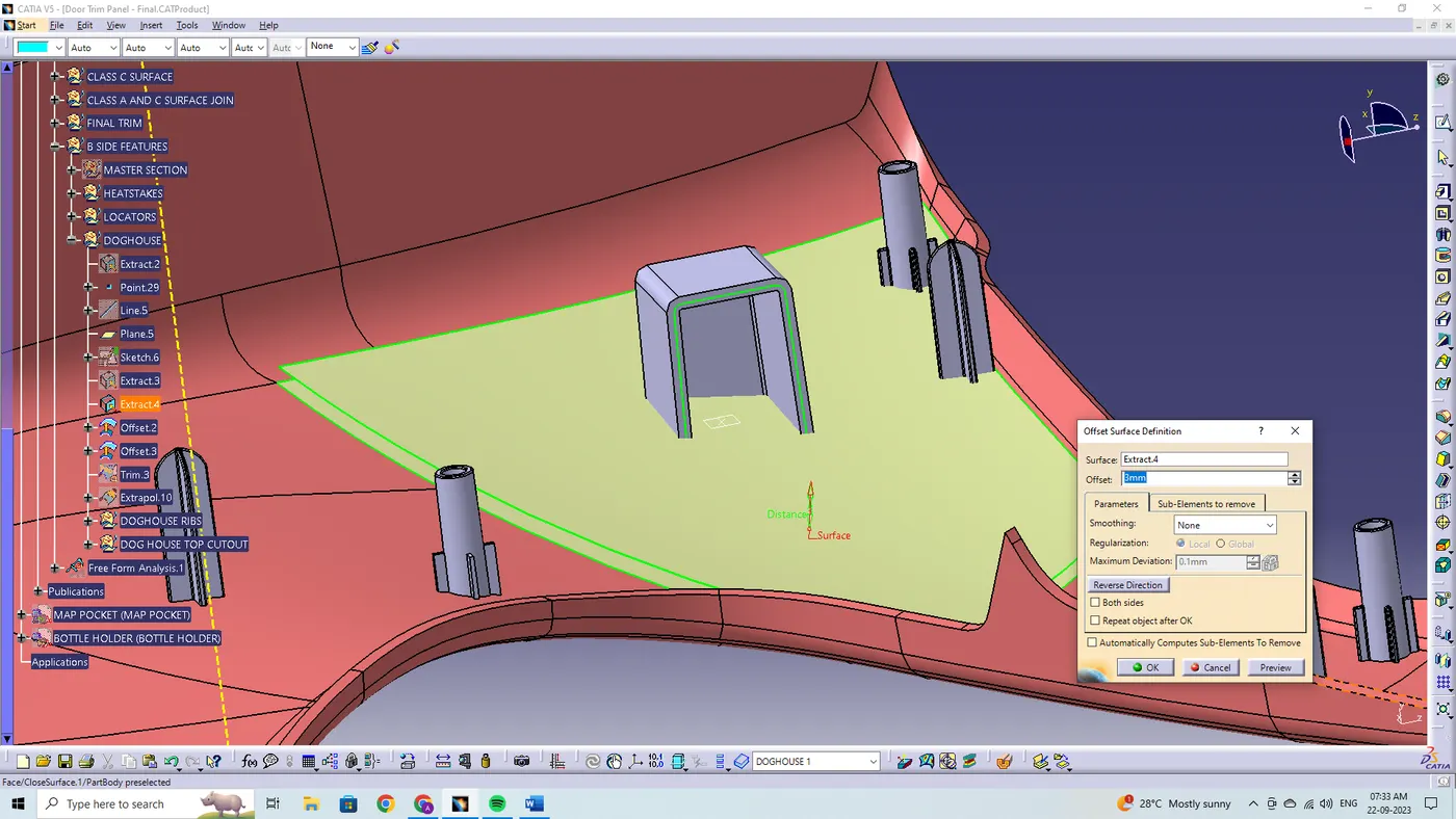
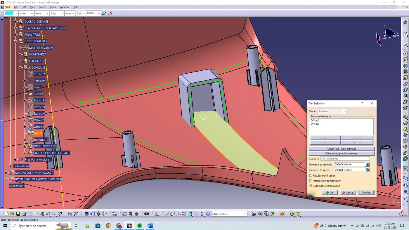
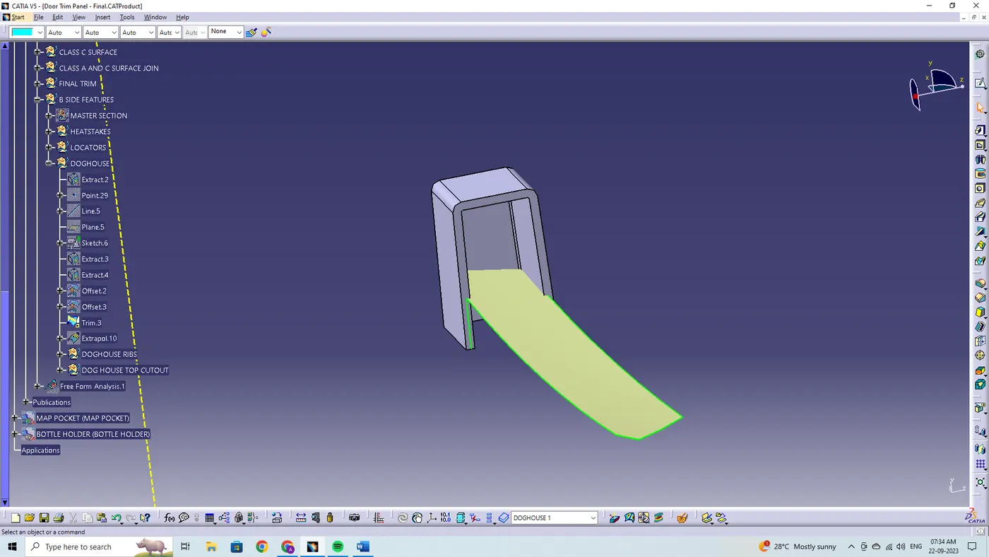
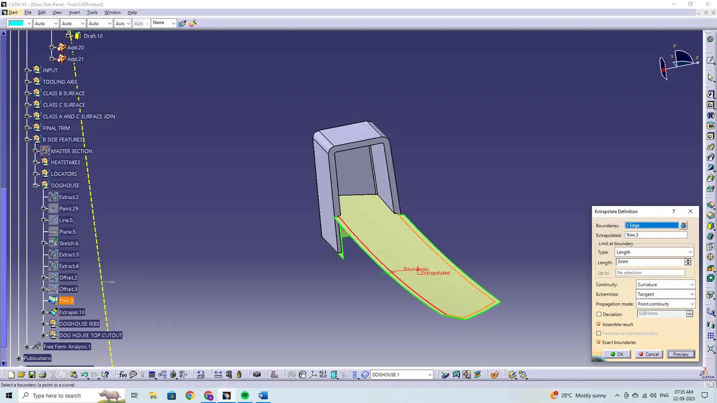
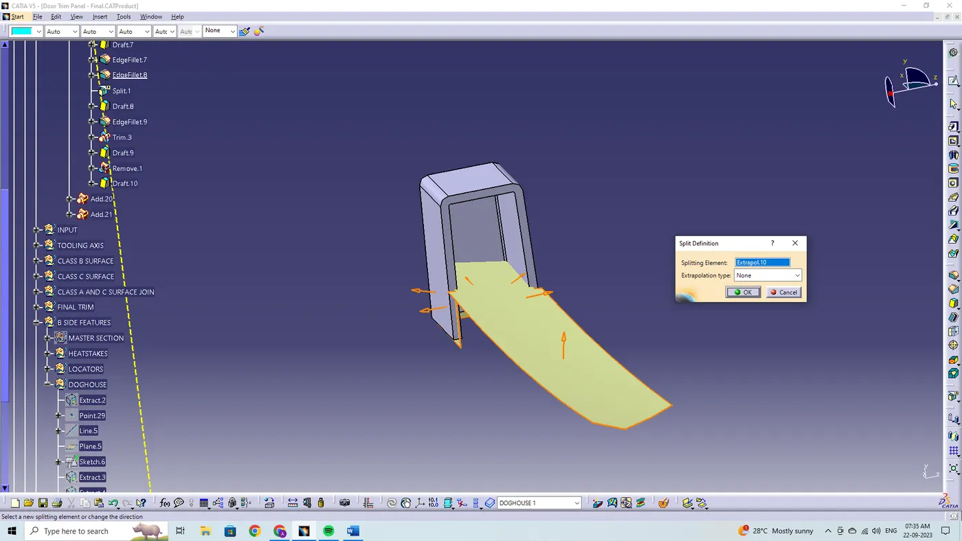
By using the draft definition, the faces are being selected to draft and the pulling direction are being selected as a side core axis also the neutral element to draft are being selected.
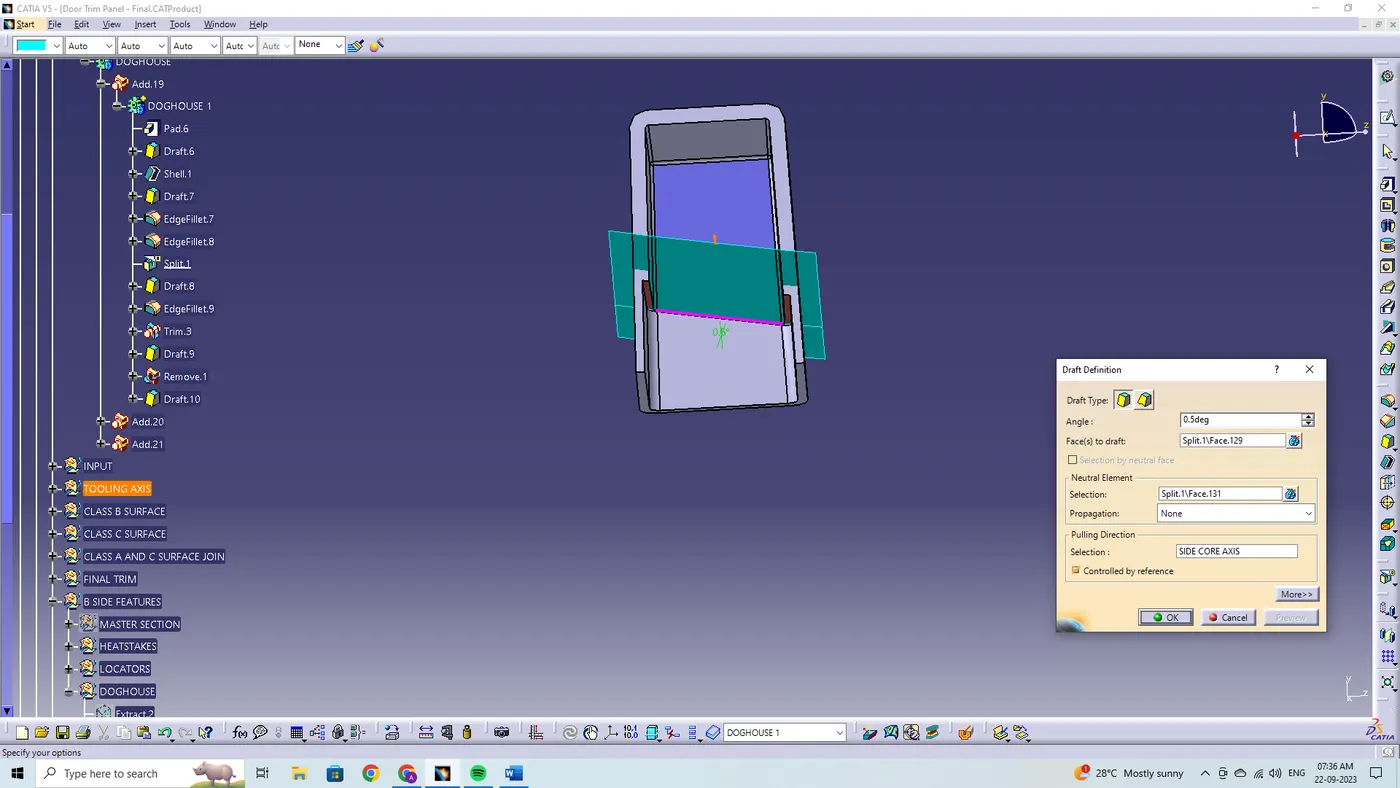
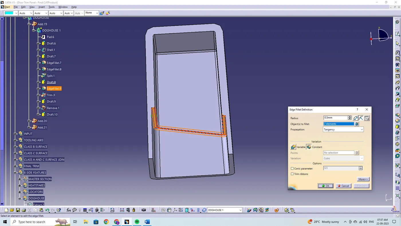
Now, we create rib part of the doghouse, so we create a line, point and a place for creating a positioned sketch. And then we do the same process of pad, draft and fillets for the ribs and union trim with doghouse to get the desired doghouse design.
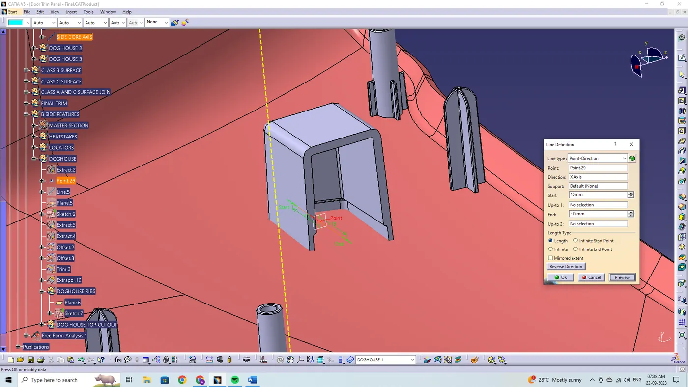
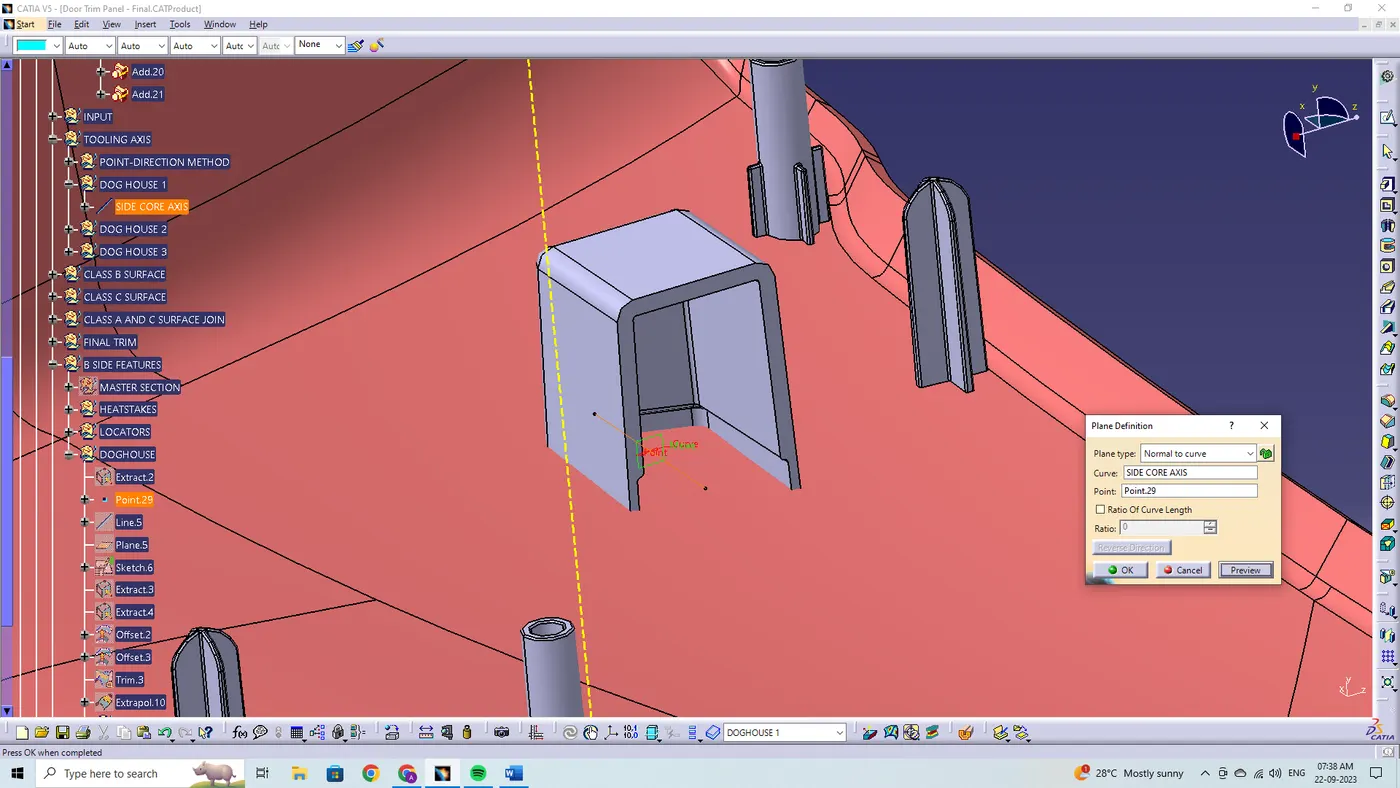
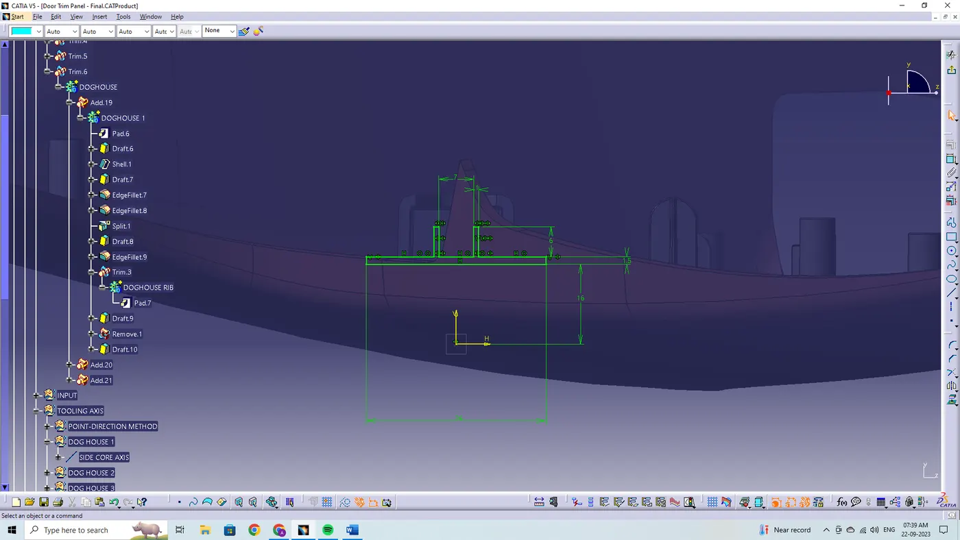
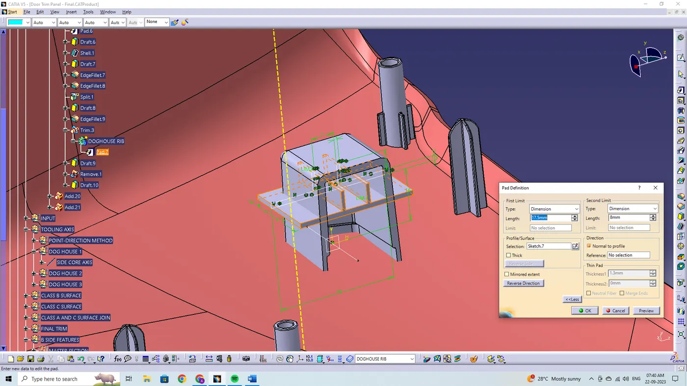
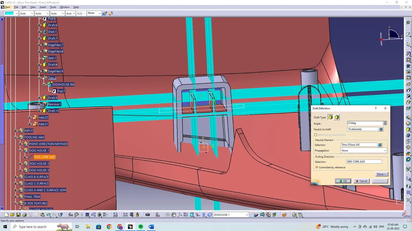
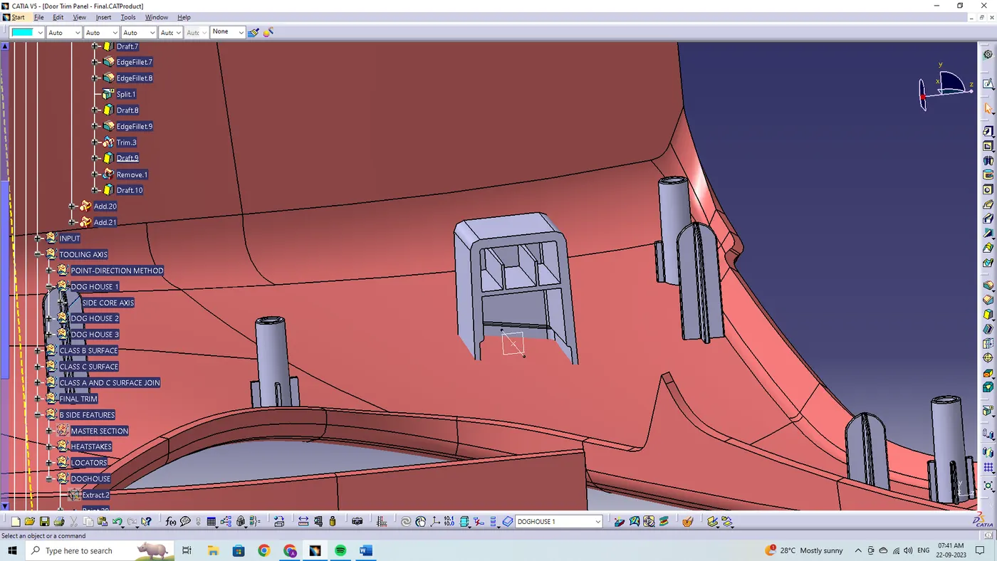
Here, we need a top cutout for attaching push pin/clip to the top of the doghouse. So here is the process of how it is done.
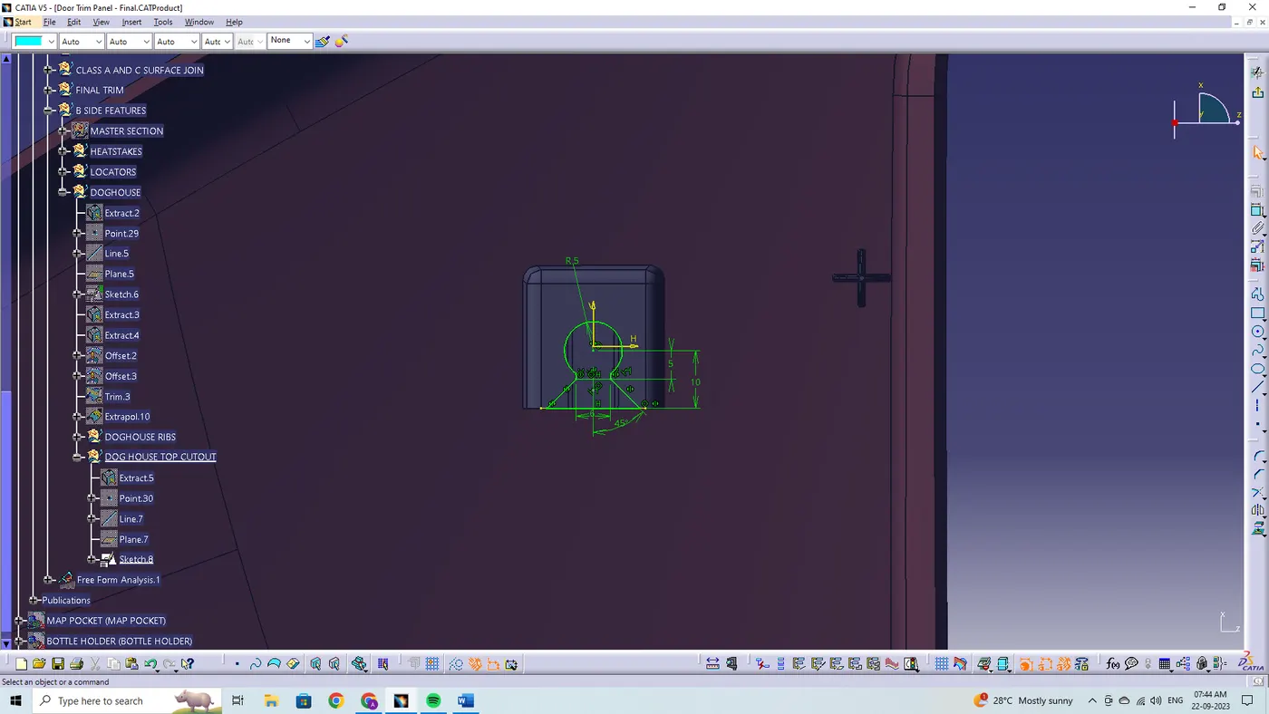
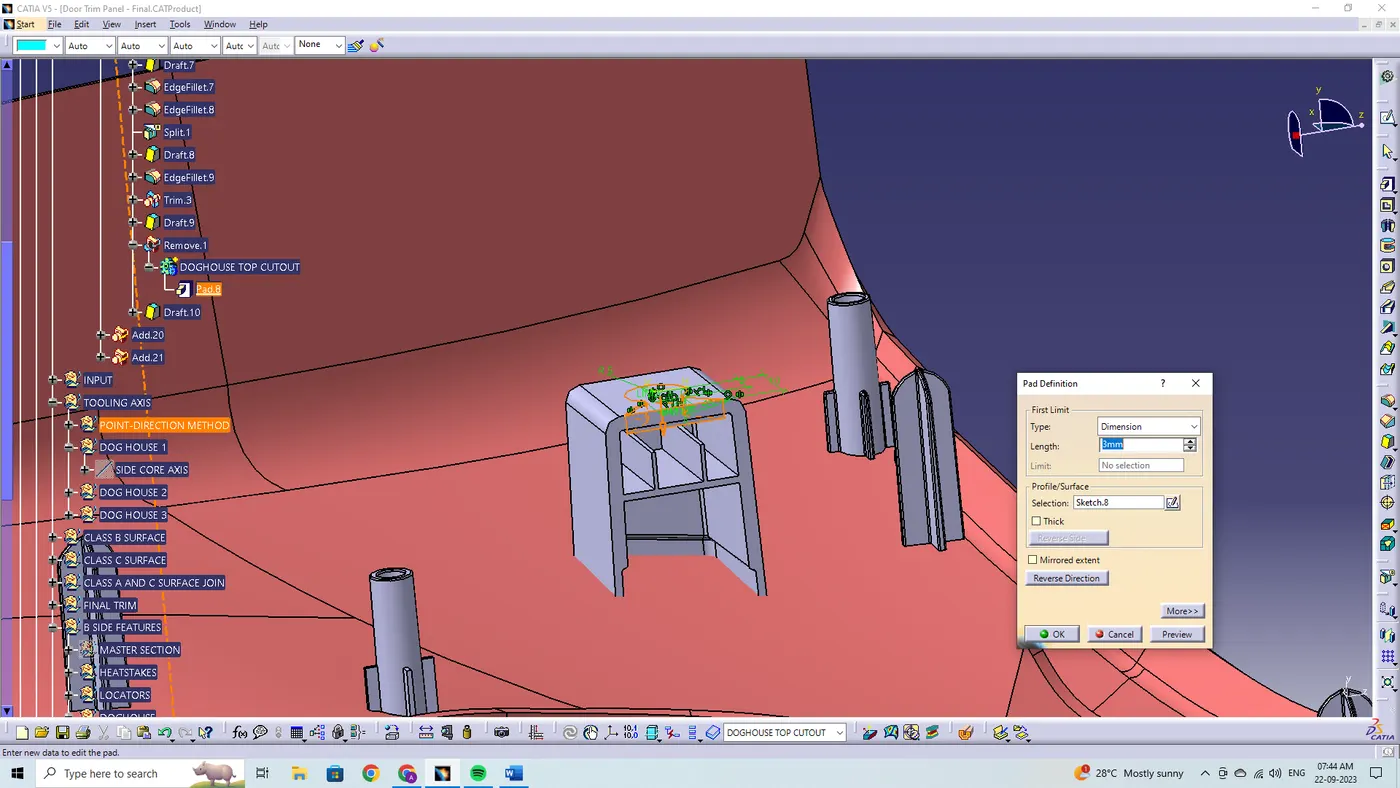
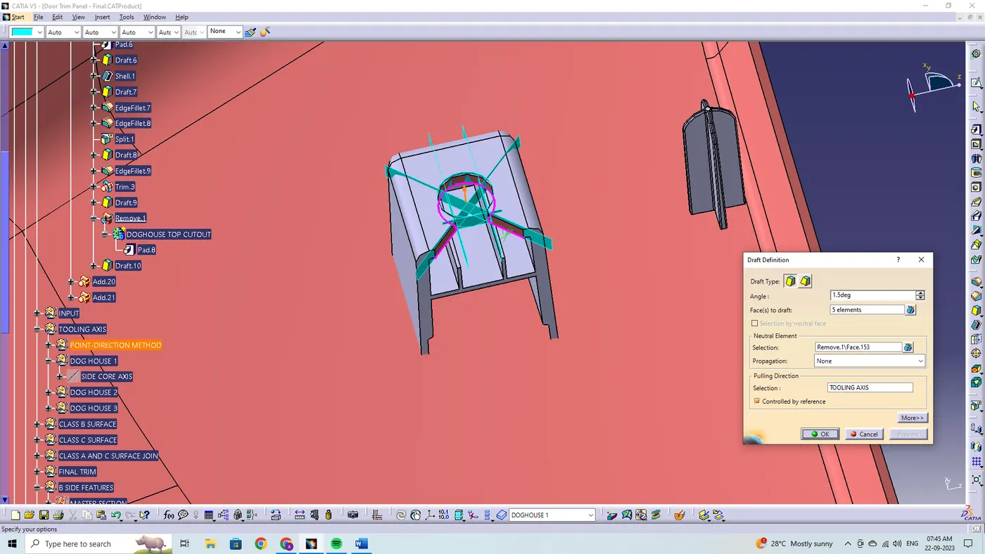
DRAFT ANALYSIS:
The draft analysis has been performed on the final component created as a closed body using the part design closed surface feature. For plastic components the minimum angle required for the draft to be 3 degrees.
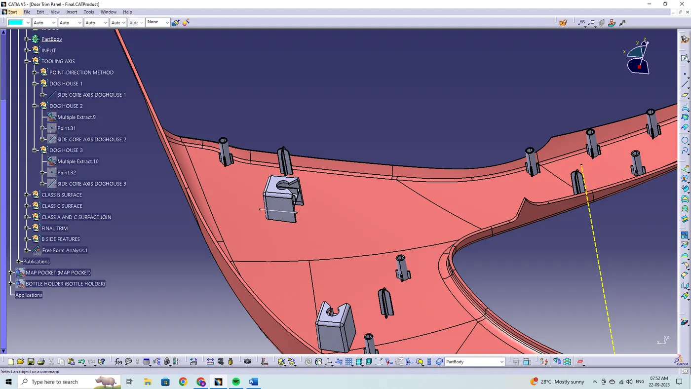
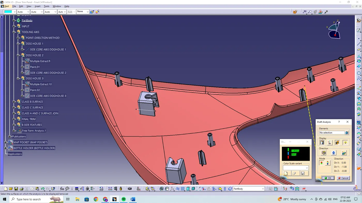
The direction compasses are to be selected and placed on the main tooling axis line and the compass is being locked using the lock feature in the direction.
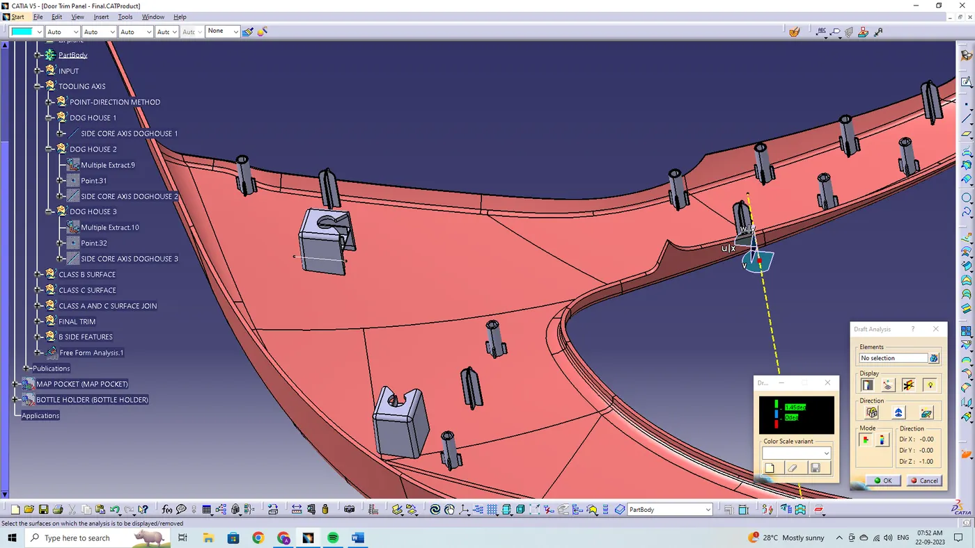
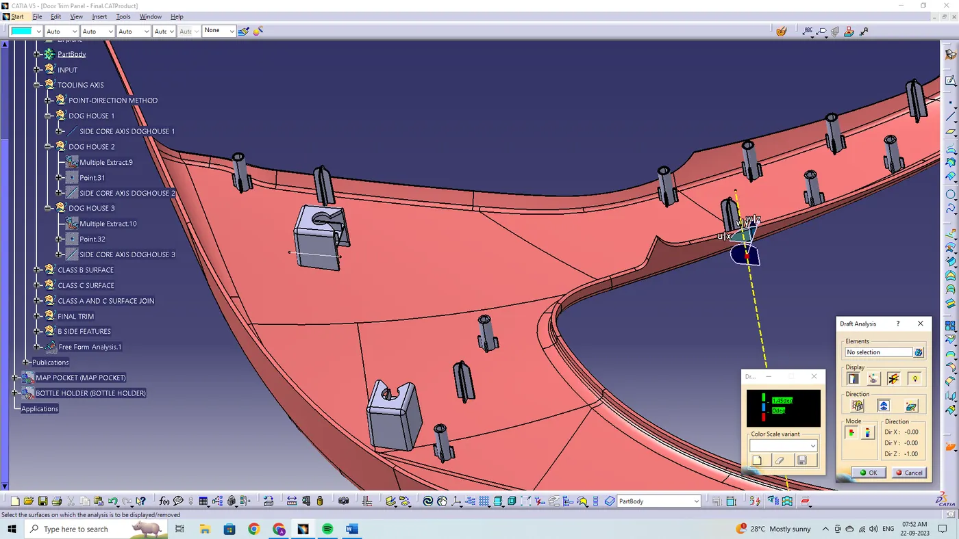
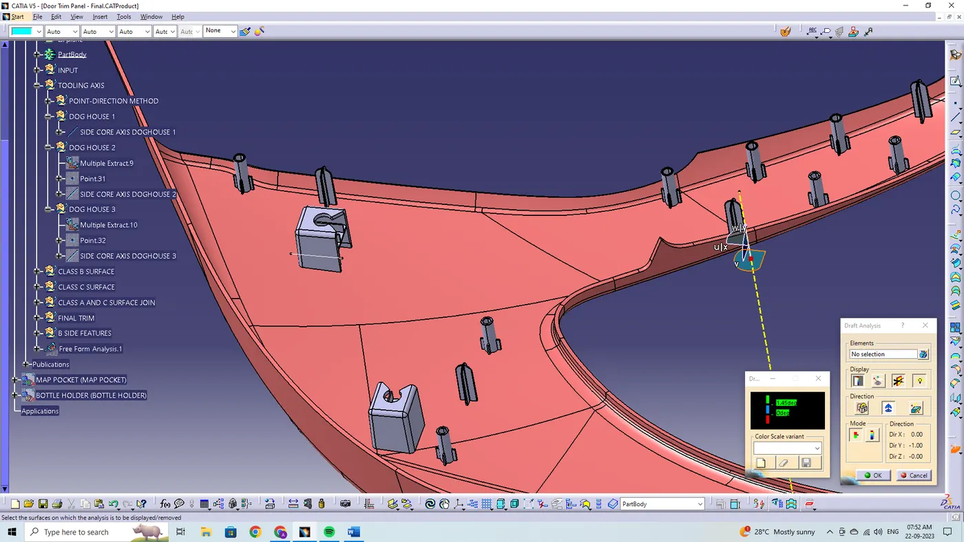
In the display window the color code variants are being selected, to know the range of the draft in the class A surface. In the display window the color variant shows,
- For 3 degree - Green color variant (Positive)
- For 0 degree - Blue color variant
- For <0>
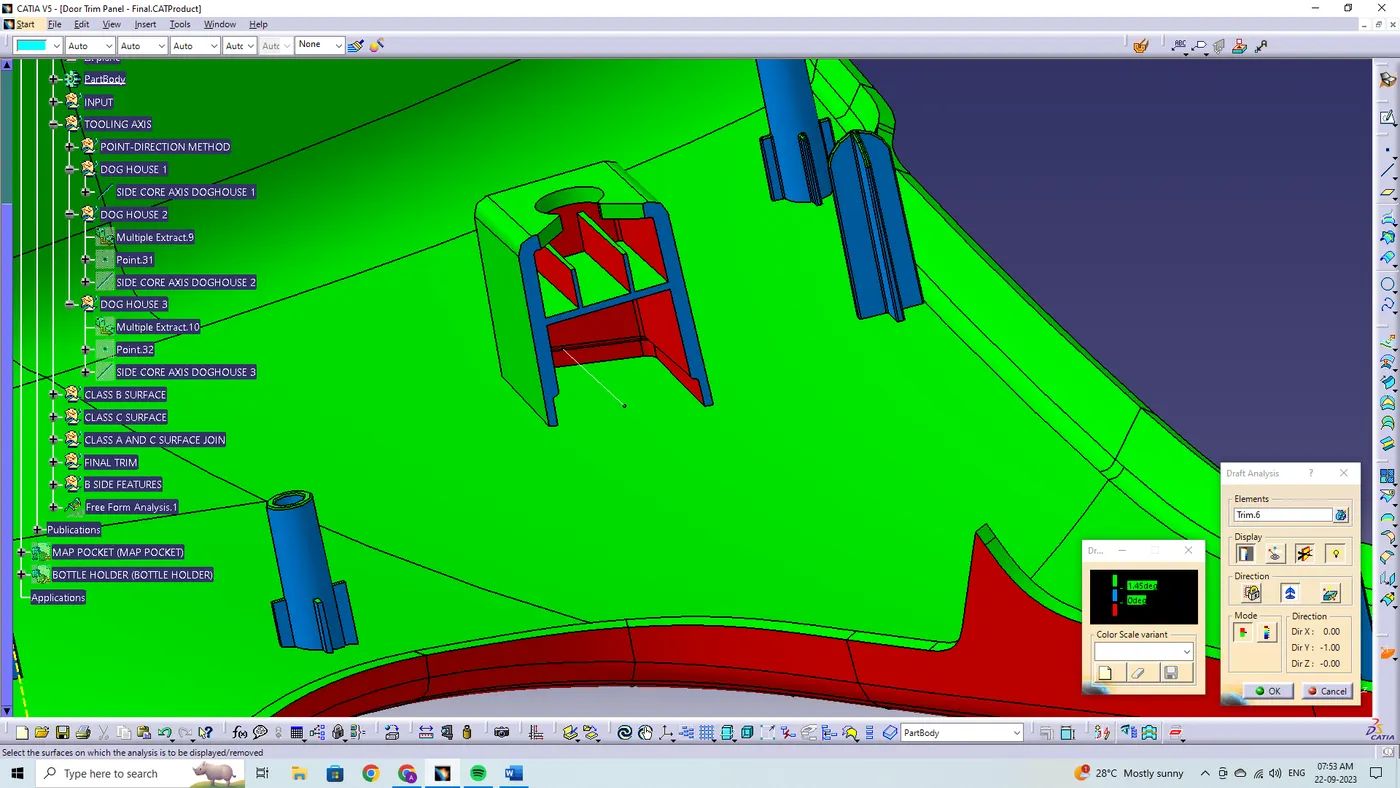
By using the side core axis, the compass is being placed on the axis to analyze draft on 0.5 degree on ribs and supporting faces which are clearing on the side core tooling axis.
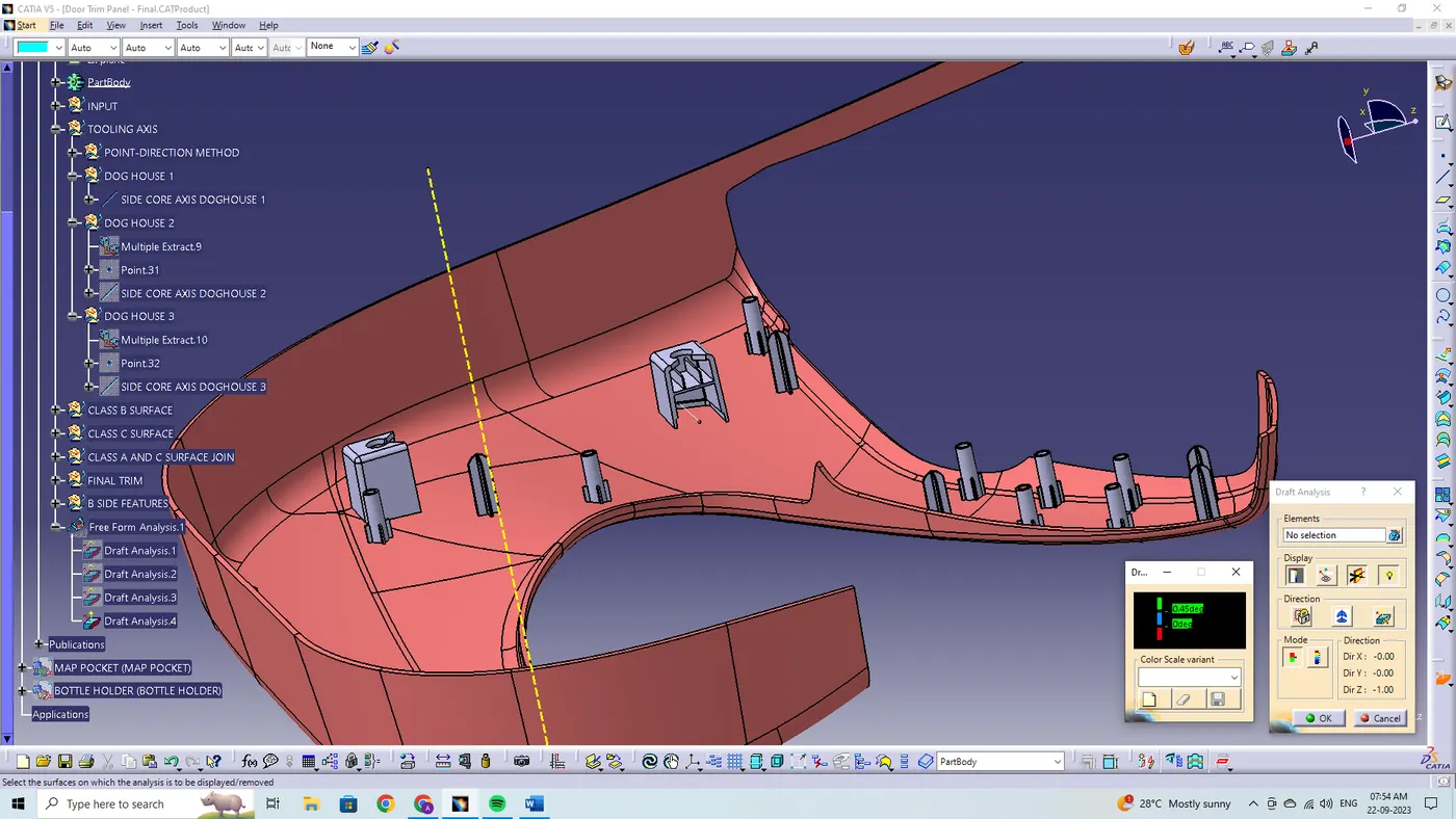
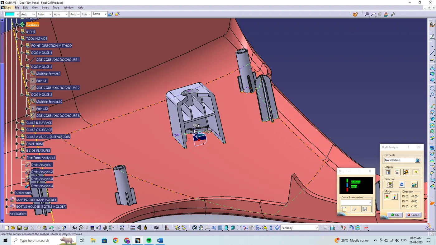
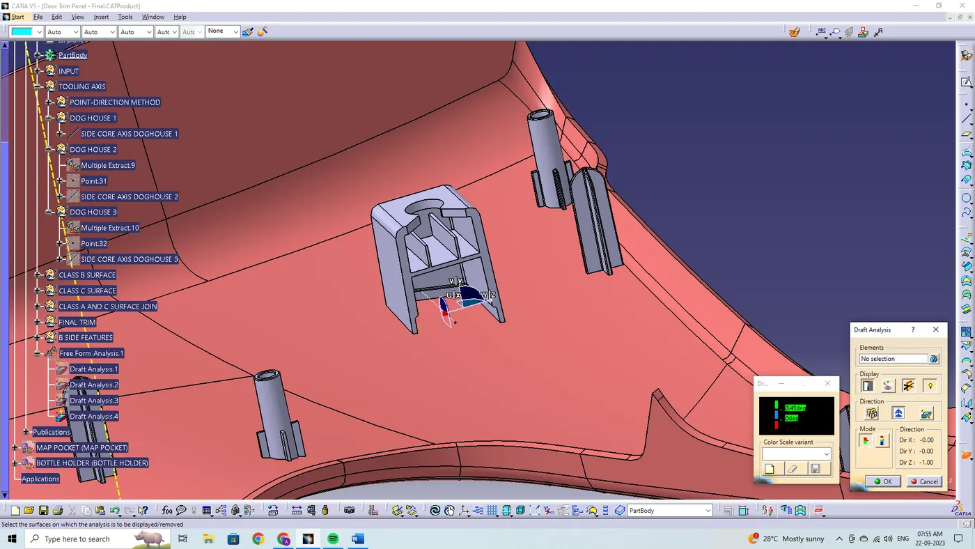
In the display window the color code variants are being selected, to know the range of the draft in the class A surface. In the display window the color variant shows,
- For 3 degree - Green color variant (Positive)
- For 0 degree - Blue color variant
- For <0>
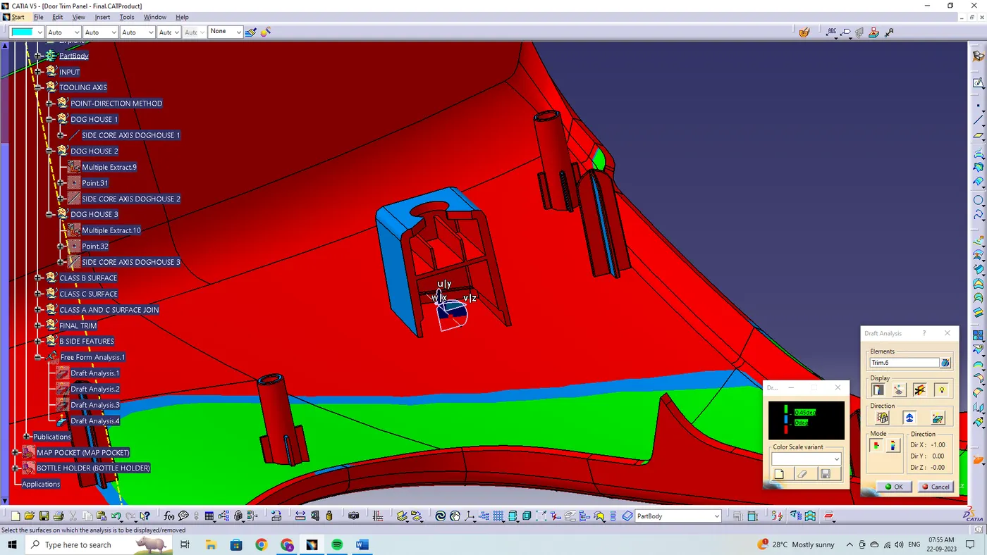
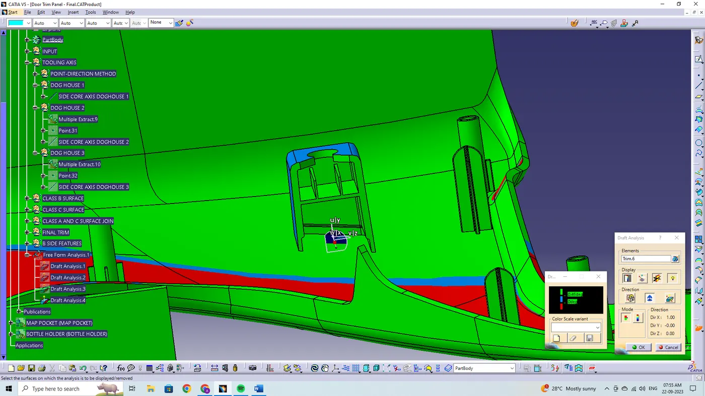
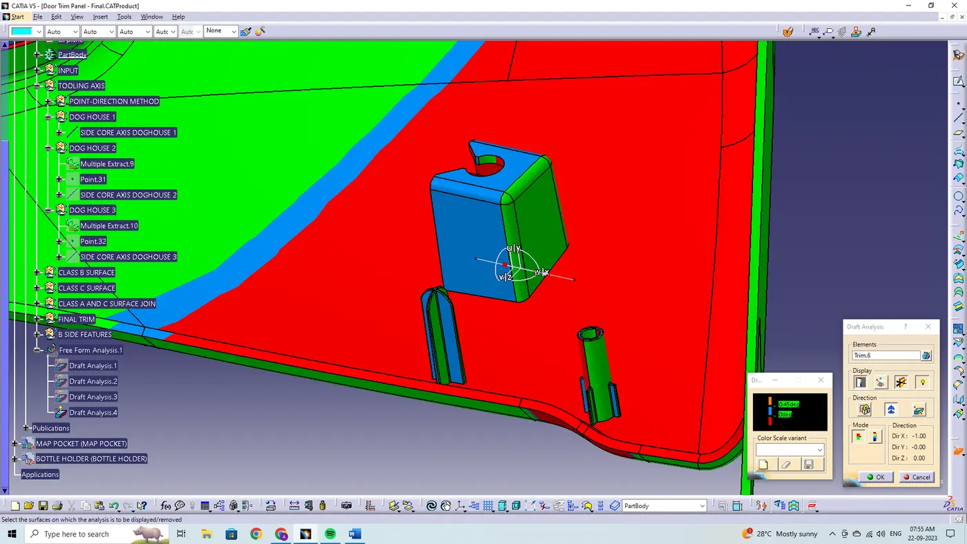
The drafting is being performed in both the core and cavity side of class A surface. The green color implies the draft angle is in the positive region. If the draft angle is being inverted the color of the surface is implied as blue color.
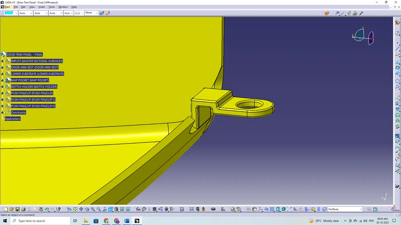
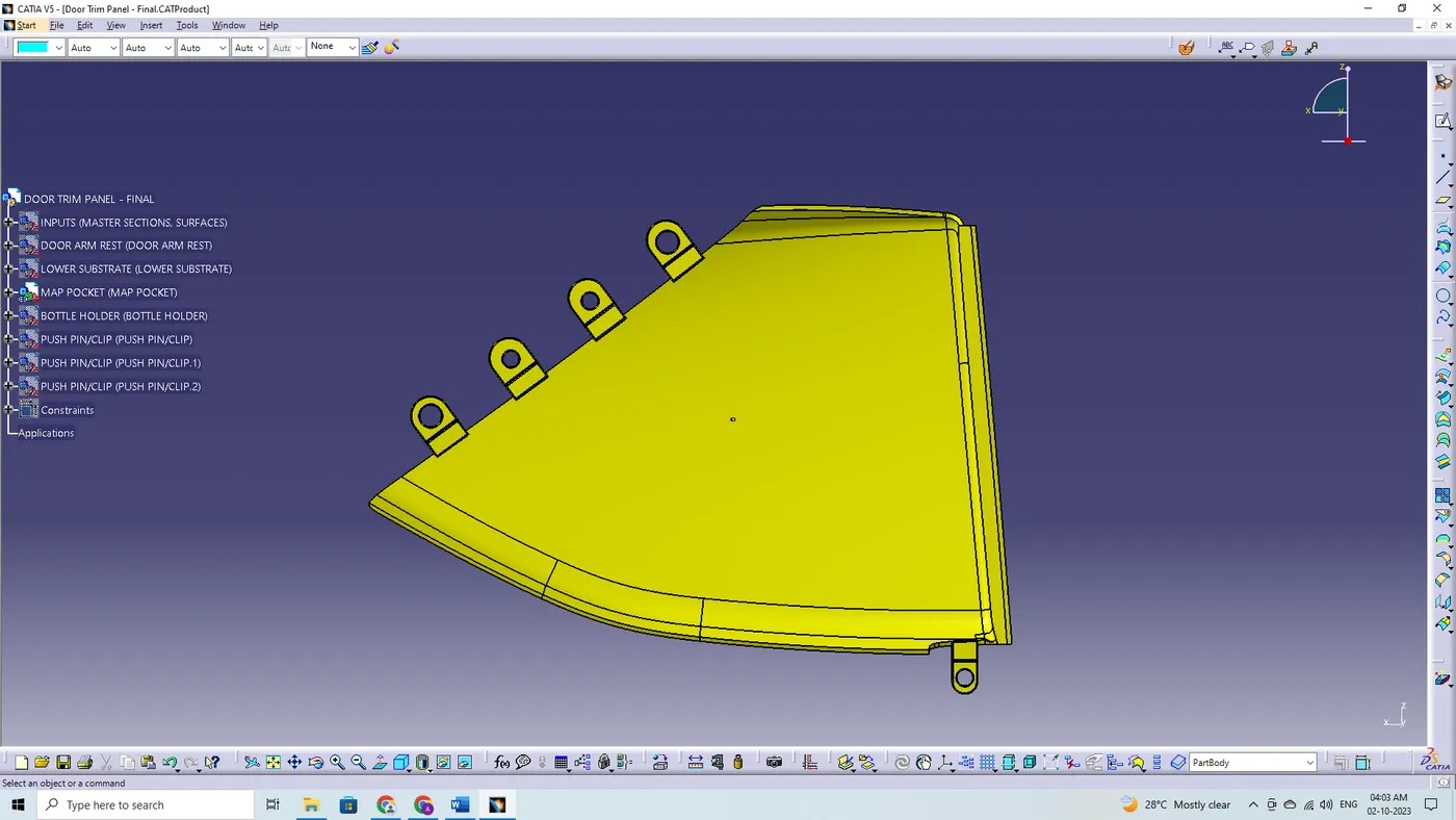
CREATING THE FLANGES AND COUNTER CLEARANCE HOLE:
By using the master section, the flanges are going to be designed.
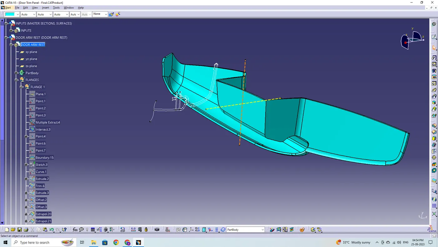
By using the point definition feature the points are created between two points to make the centre point of the master section.
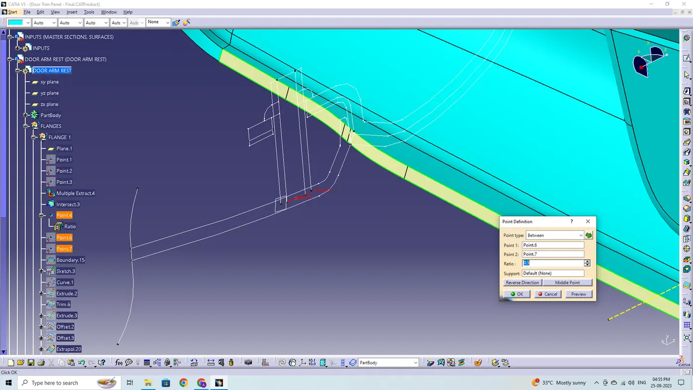
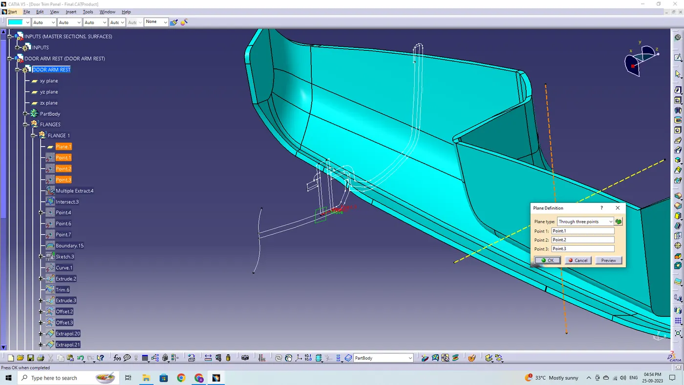
By using the plane definition feature the respective planes are being created at the point reference from the master section.
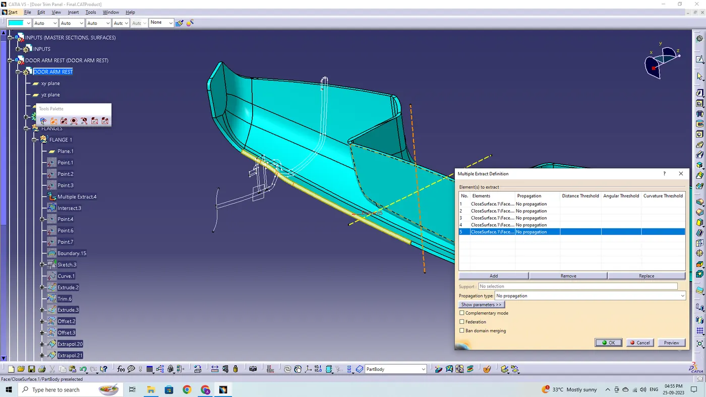
We need C surface to start with, so we take multiple extract of the C surface from the component.
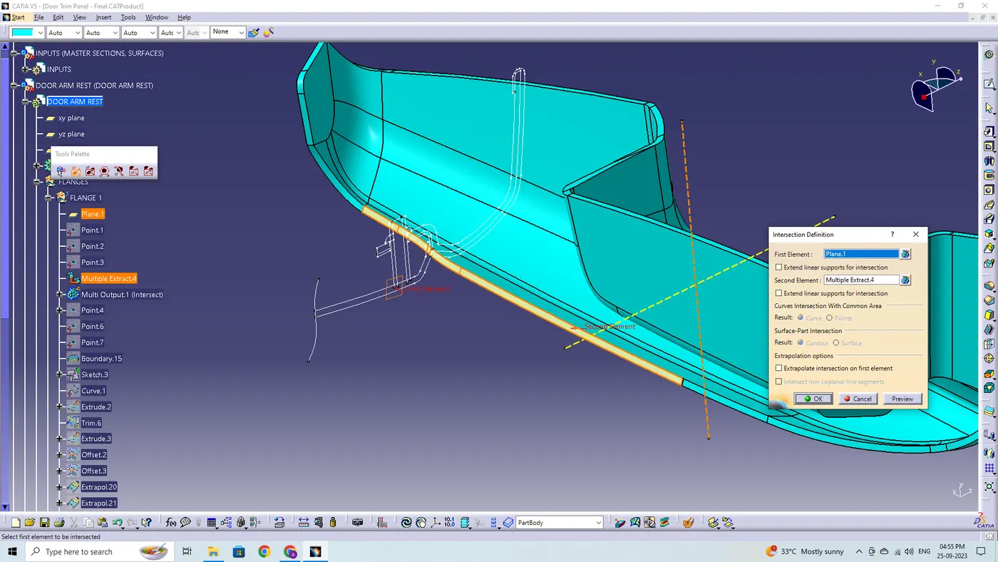
By using the plane and the projection point, positioned sketches are being created to sketch the profile of the heat stake with respective inner diameter and outer diameter.
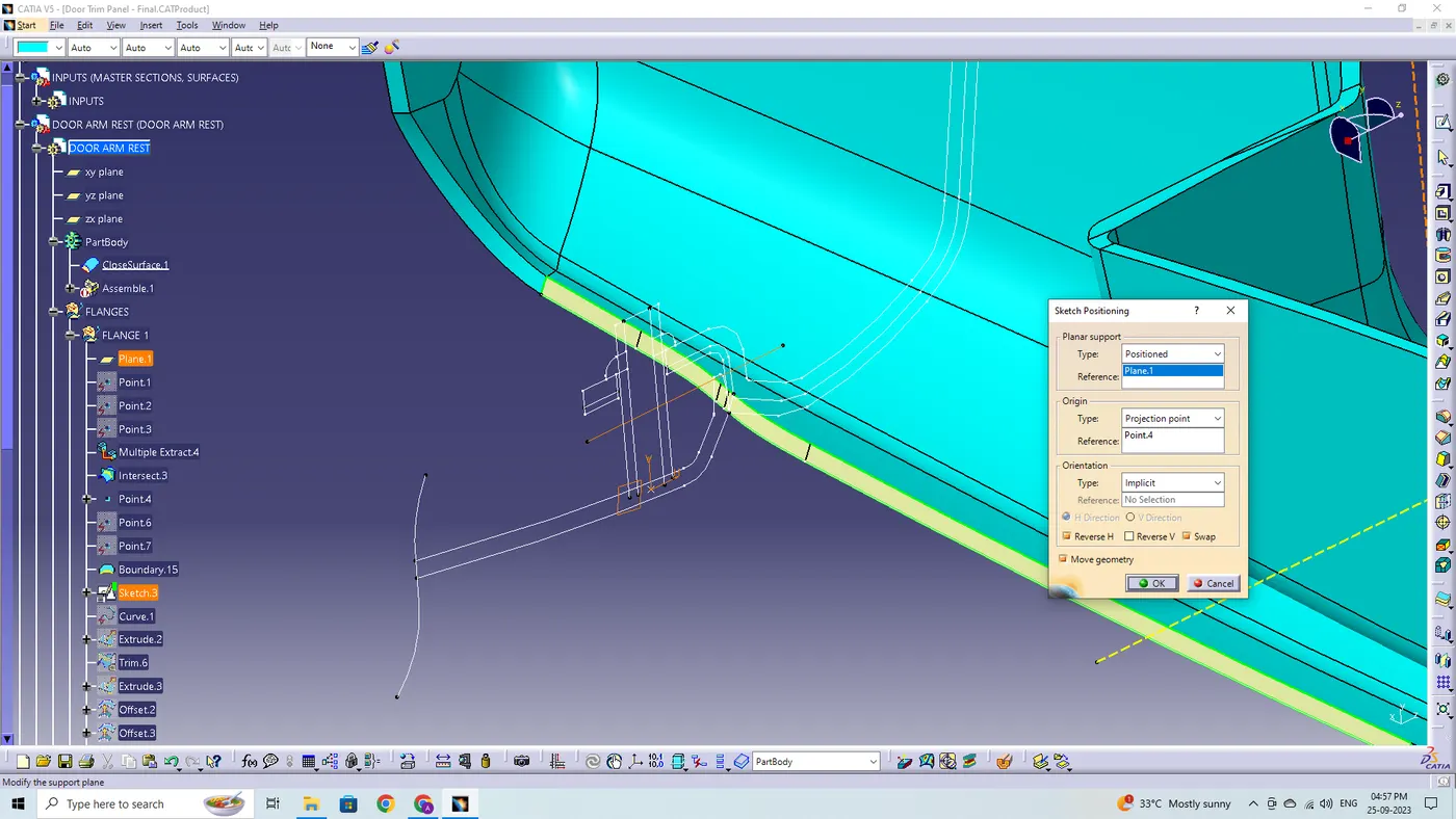
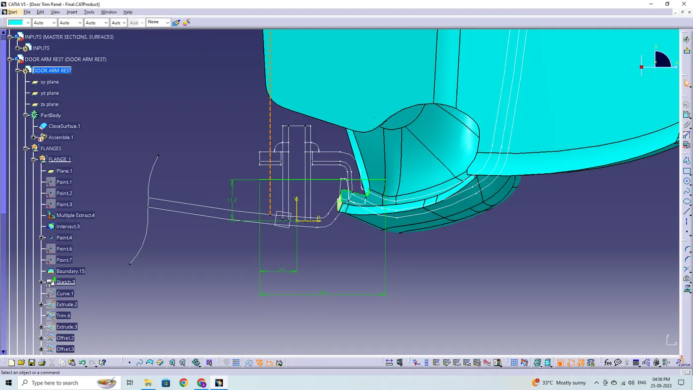
Now we extrude the sketch to make a flat surface of the flange.
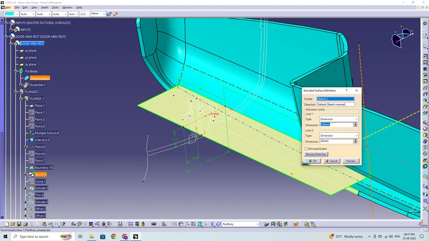
Here, we take a boundary for the multiple extract taken earlier to extrapolate the extracted surface.
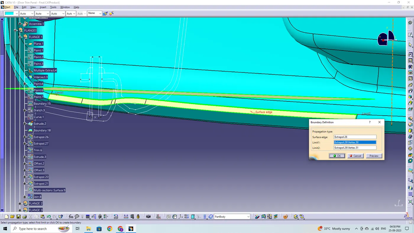
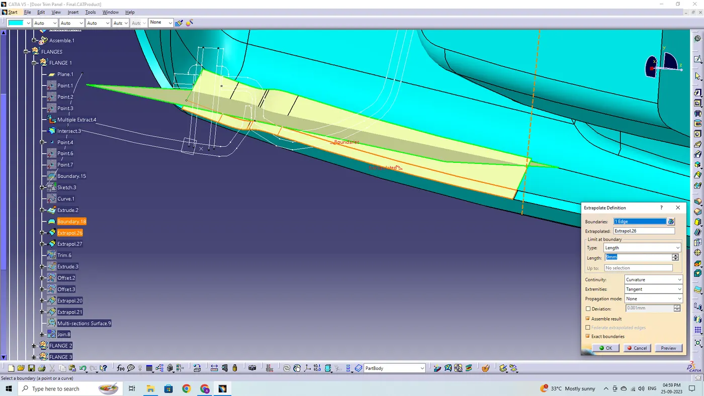
Then we trim both the extrude and extrapolate surface to get the surface shape of a flange.
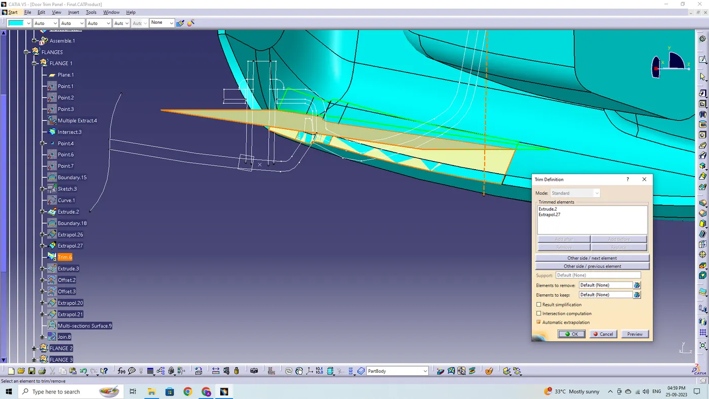
Then we apply, thicken surface command option to the trimmed surface and we arrive at the flange part. Now as we don't need this much length, so we create a surface perpendicular to the flange.
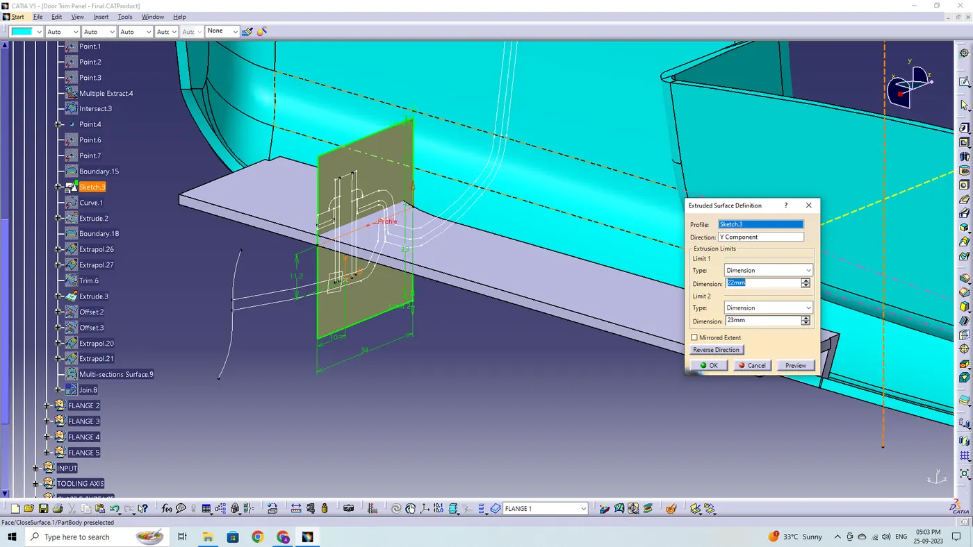
Later, after creation of the perpendicular surface we offset the surface in two opposite directions so that we get the flange width of 20mm.
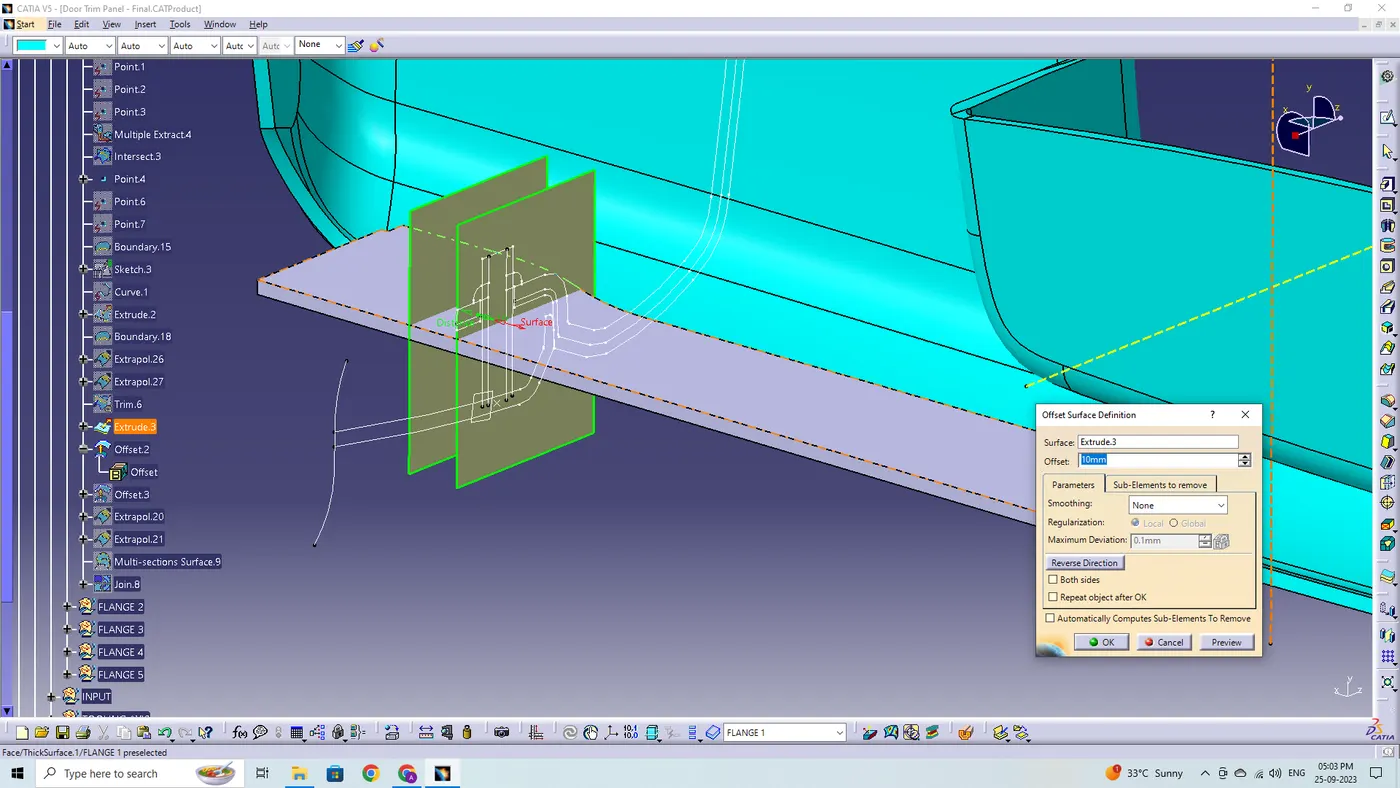
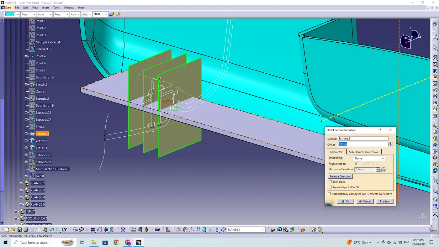
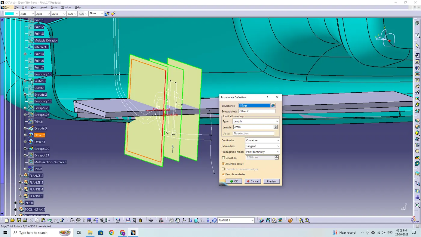
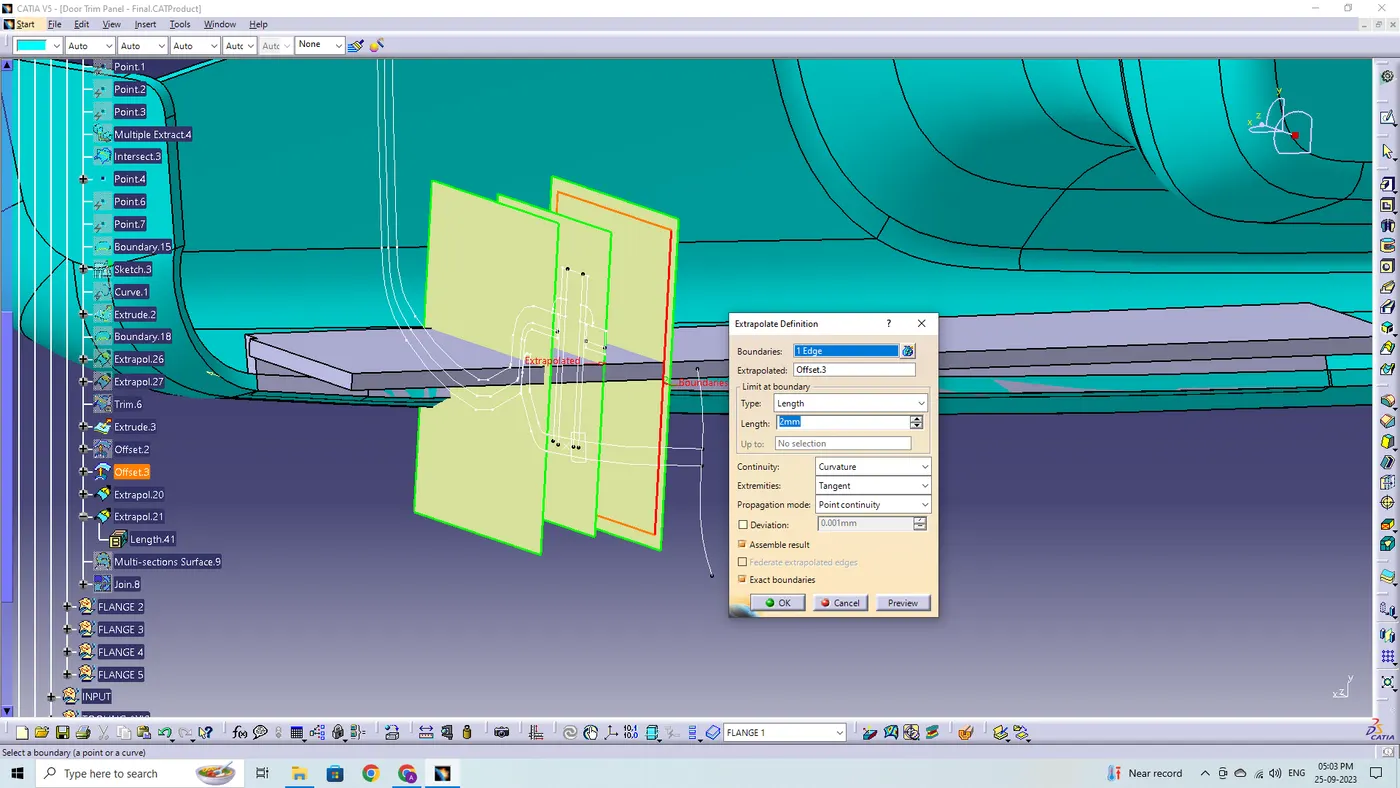
We extrapolate the offsetted surface a few mm on all sides so that it is crossing the flange side width.
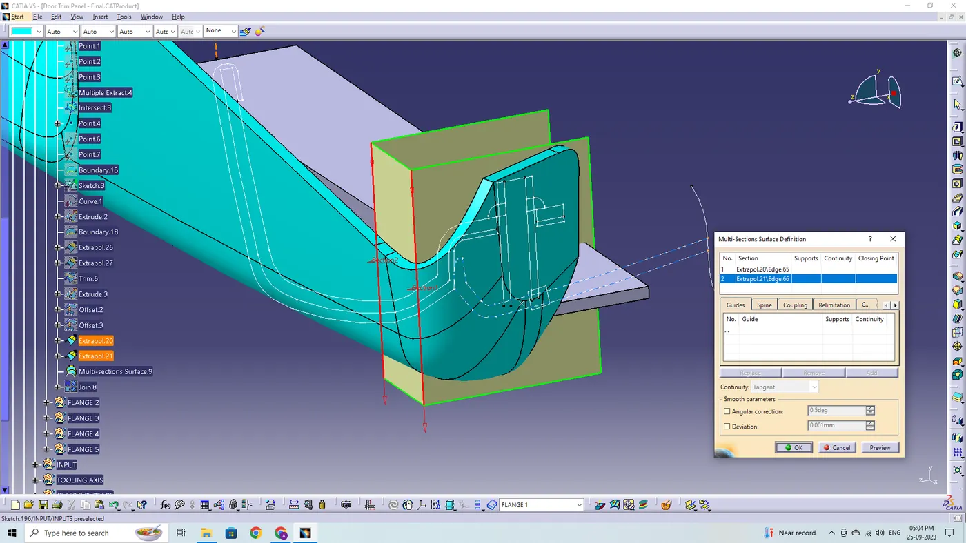
Here, we use multi-section option to create a back surface to join the two offsetted surfaces to arrive at a U-shaped surface.
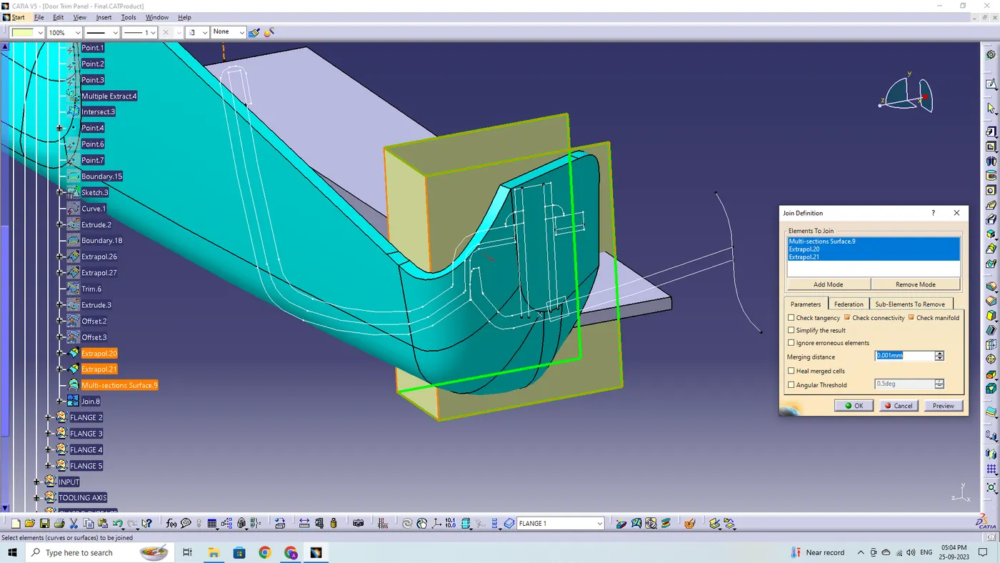
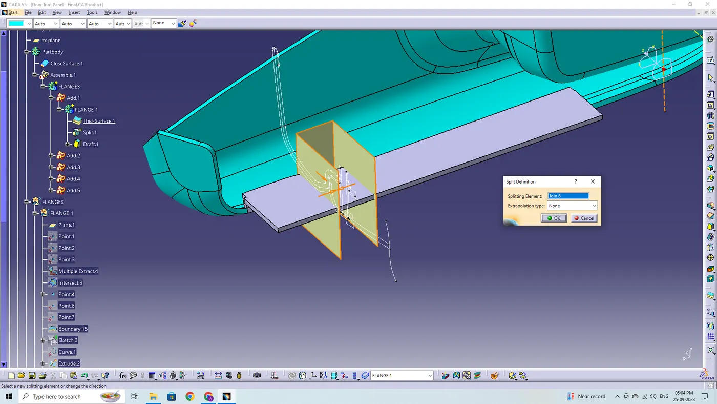
Finally, we split the surface with flange body and arrive at the flange size as per our requirement.
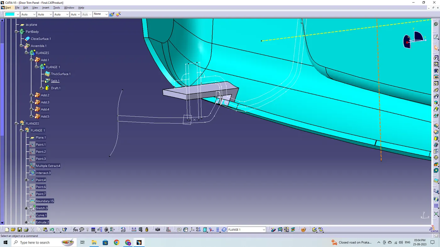
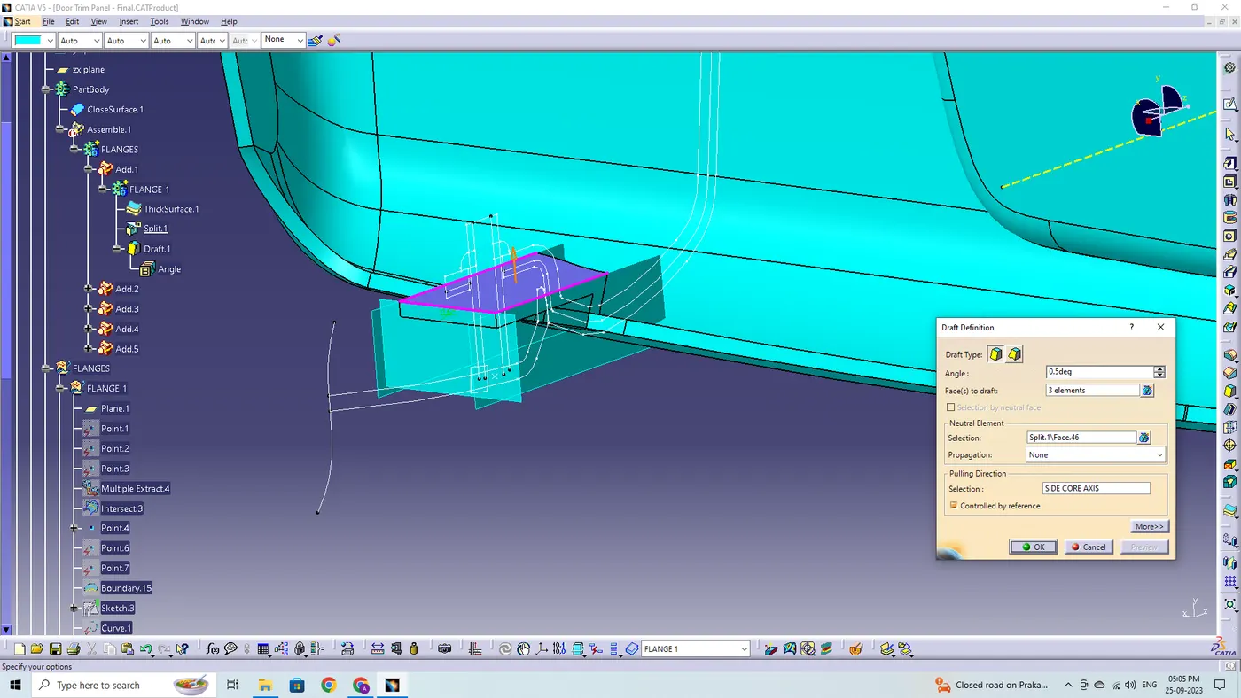
By using the draft definition, the faces are being selected to draft and the pulling direction are being selected as a main tooling axis also the neutral element to draft are being selected.
By using the edge fillet definition, the respective values are provided as per the design rules at fillet radius 10 mm for each of the front side of the flange.
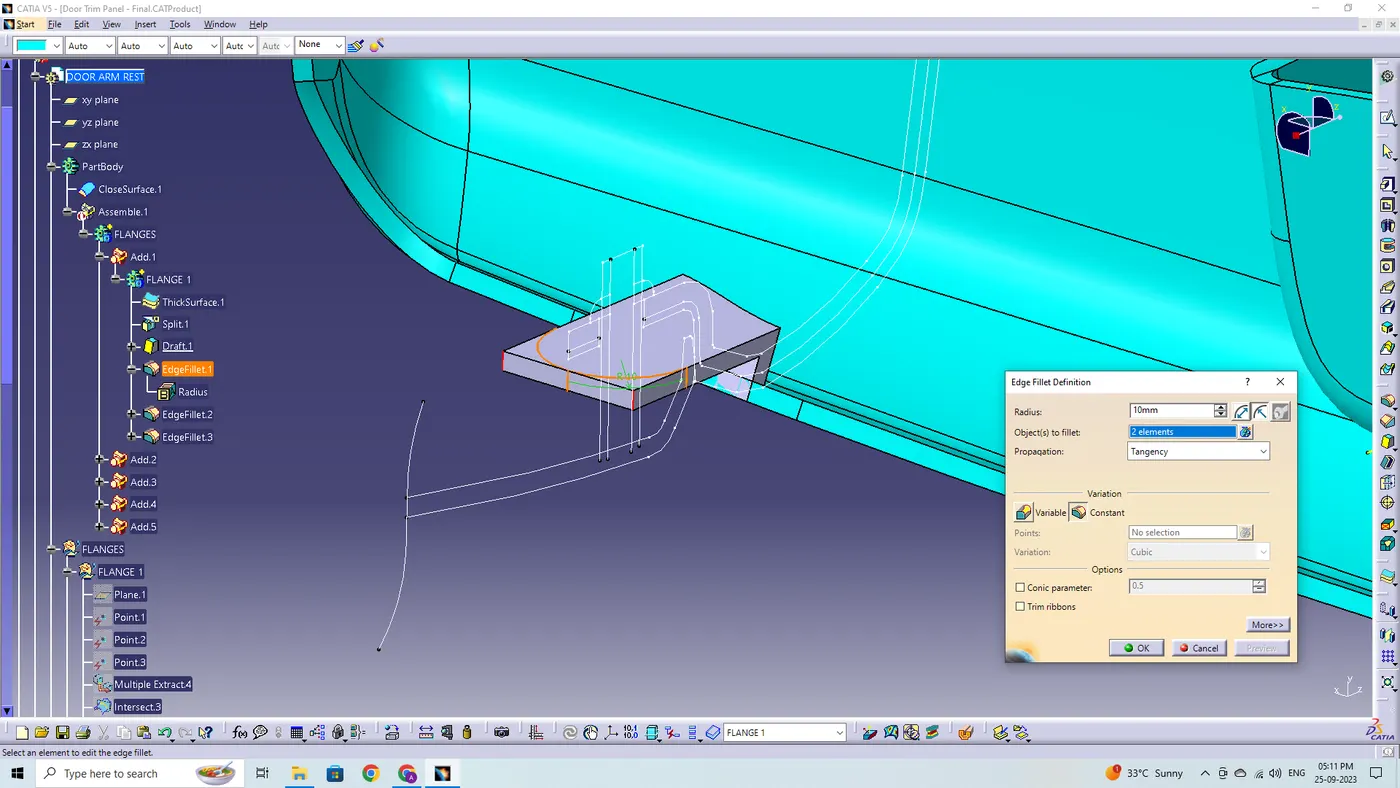
By using the edge fillet definition, the respective values are provided as per the design rules at fillet radius 3mm for the back side edge of the flange.
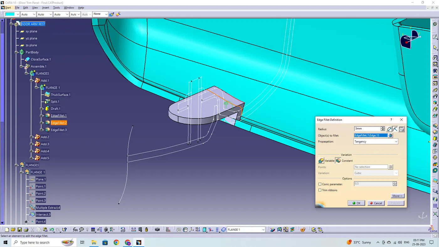
By using the edge fillet definition, the respective values are provided as per the design rules at fillet radius 0.5 mm for all the edges wherever applicable.
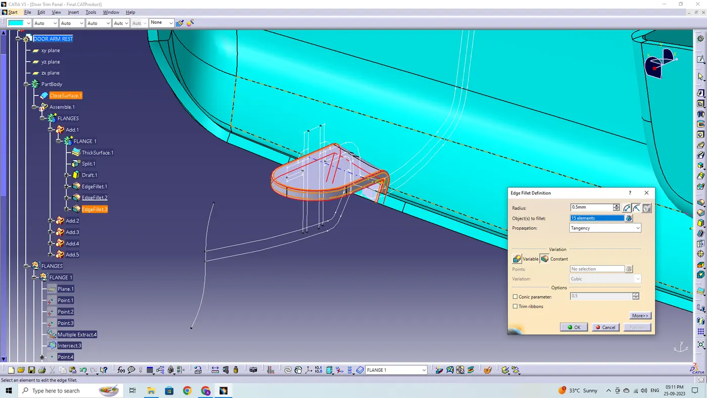
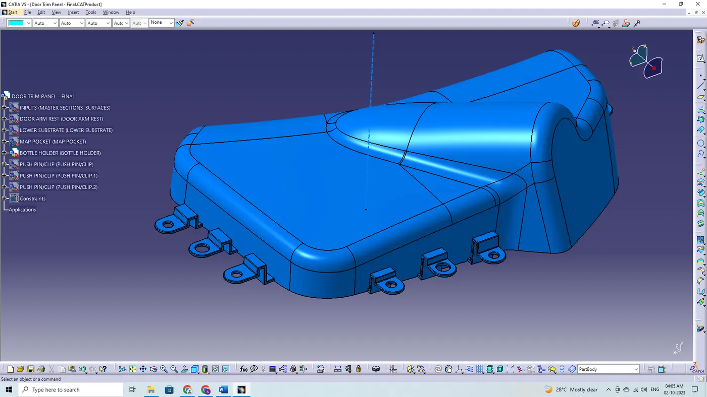
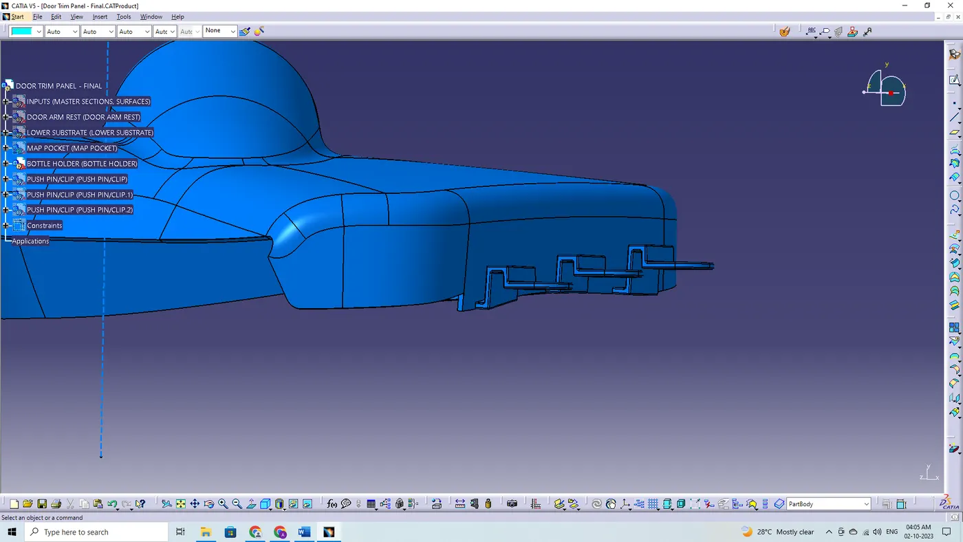
Finally, the flange is designed to the requirements.
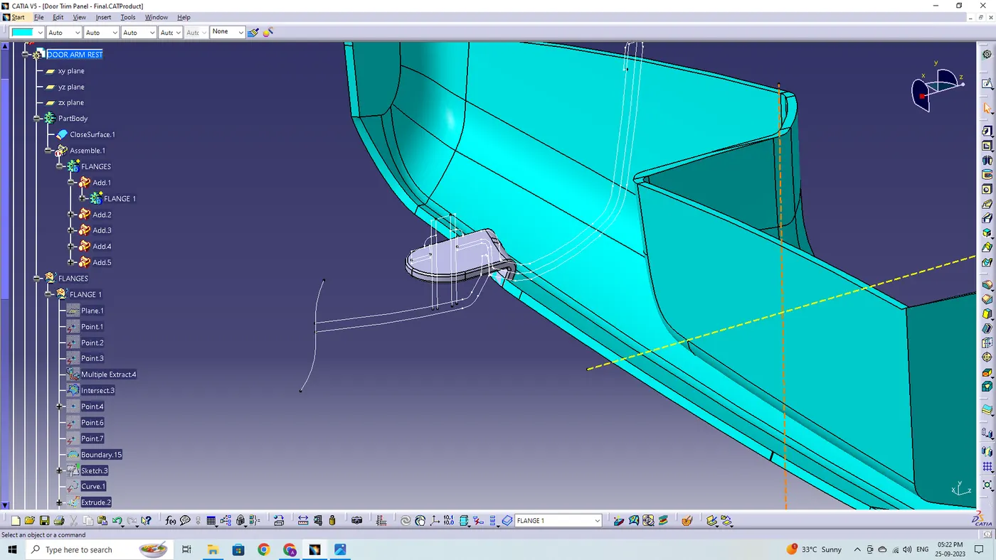
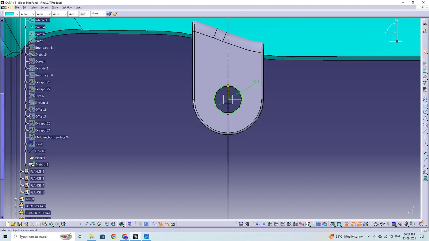
Now, we just need to make a counter-clearance hole on the flanges for the heatstakes and locators to pass through it.
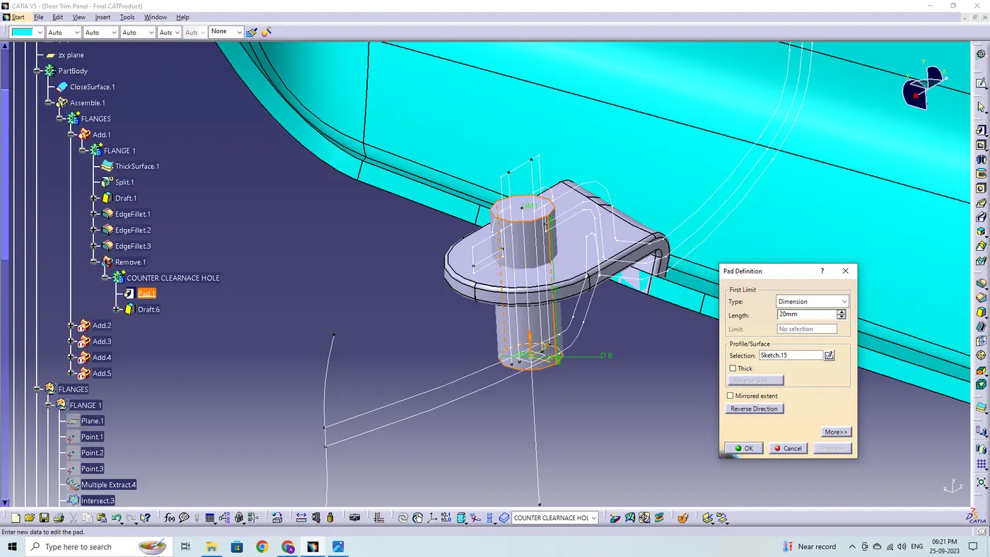
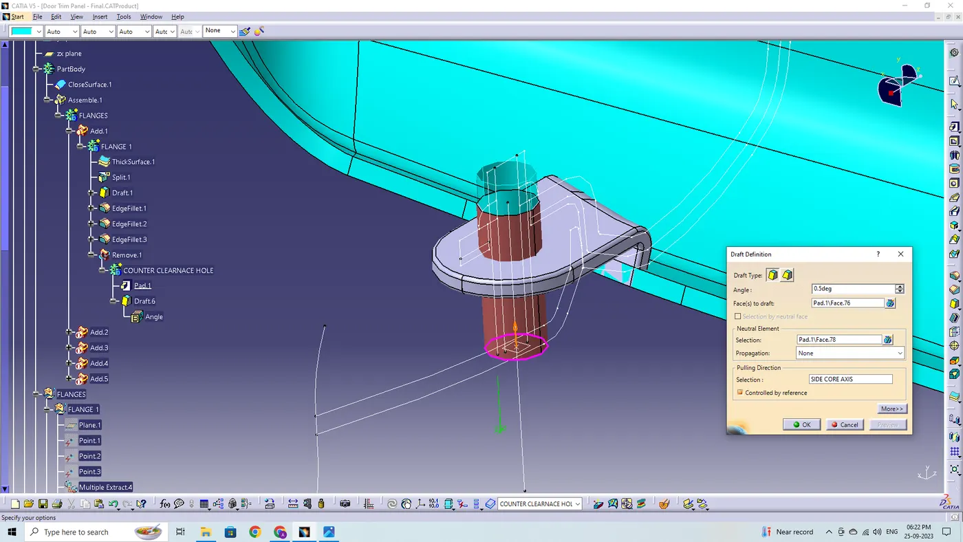
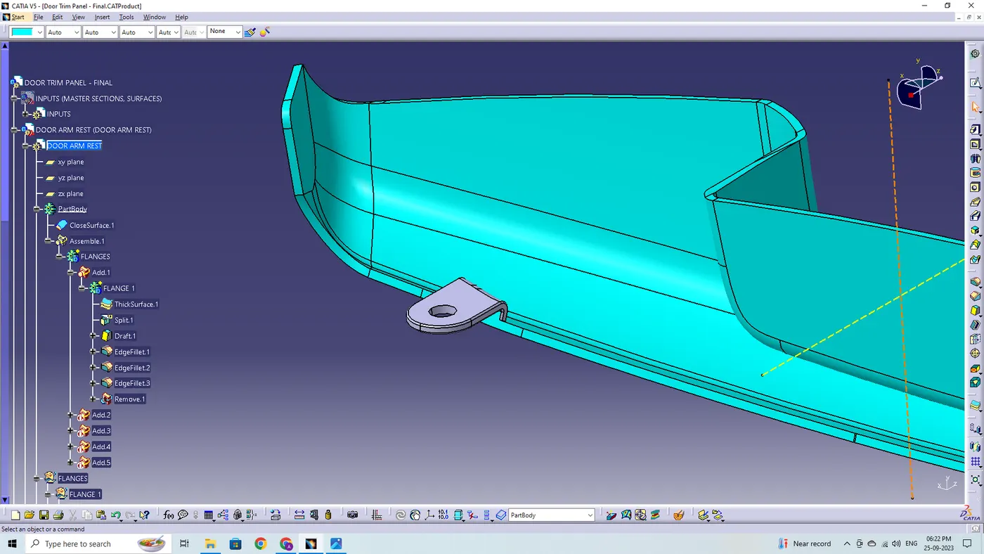
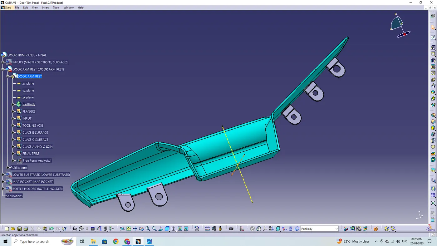
DRAFT ANALYSIS:
The draft analysis has been performed on the final component created as a closed body using the part design closed surface feature. For plastic components the minimum angle required for the draft to be 3 degrees.
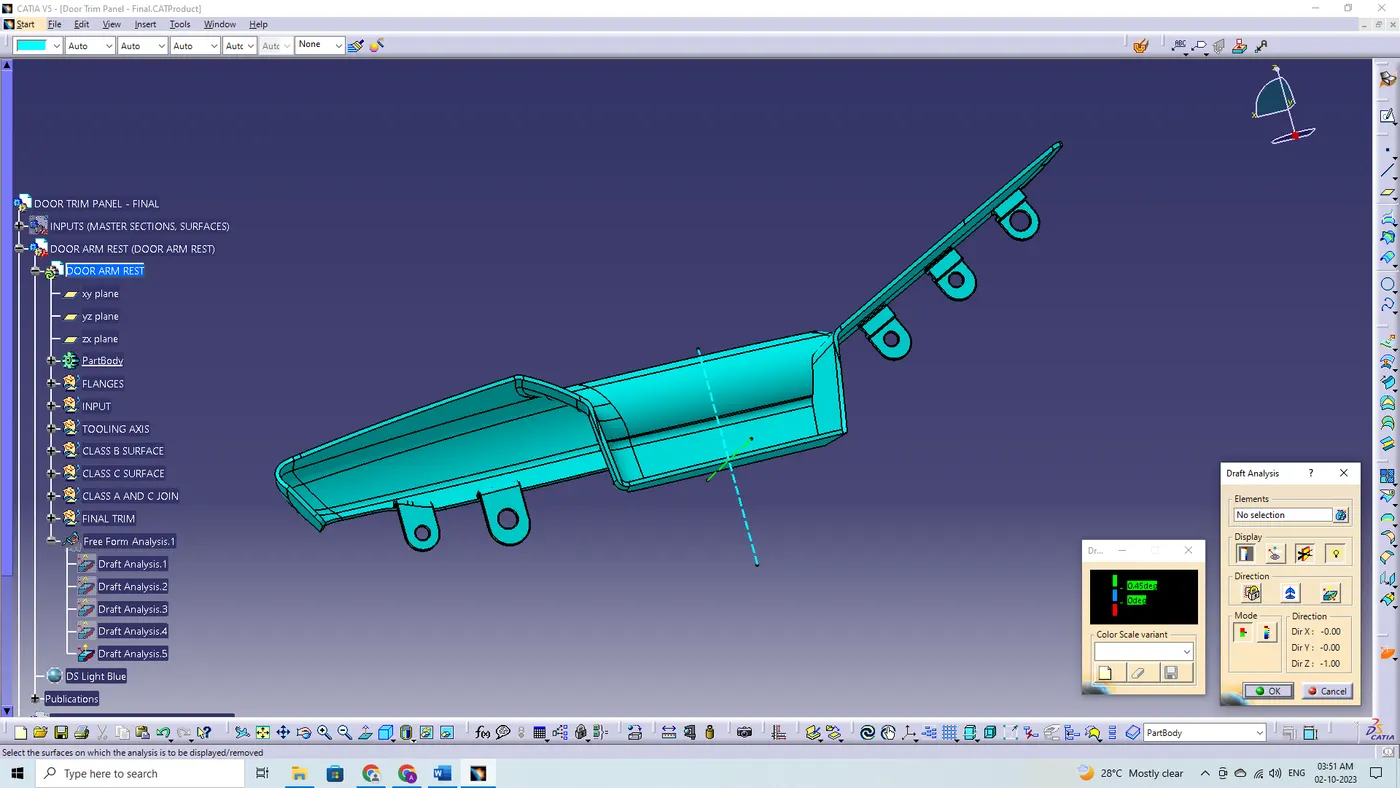
The direction compasses are to be selected and placed on the main tooling axis line and the compass is being locked using the lock feature in the direction.
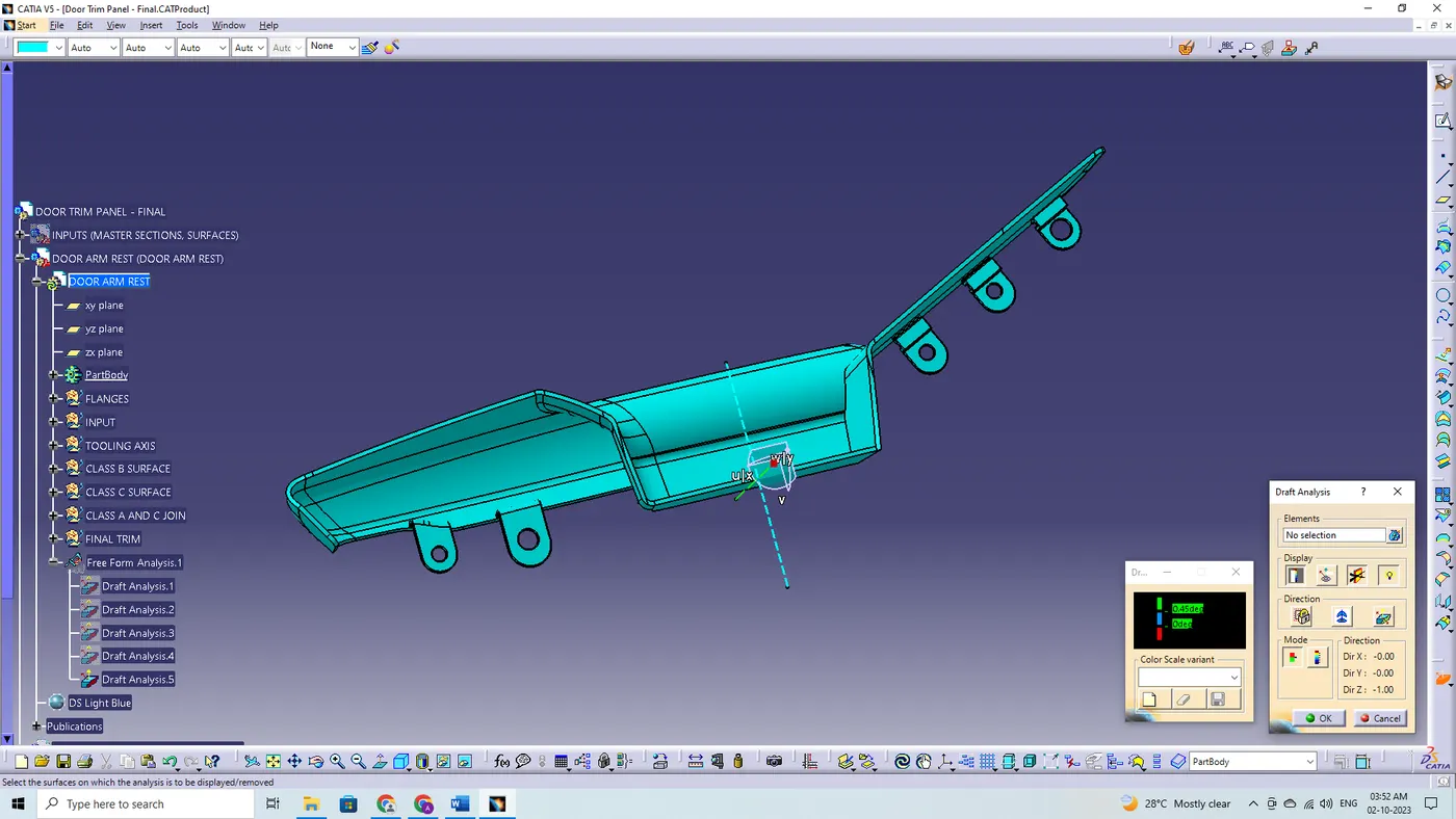
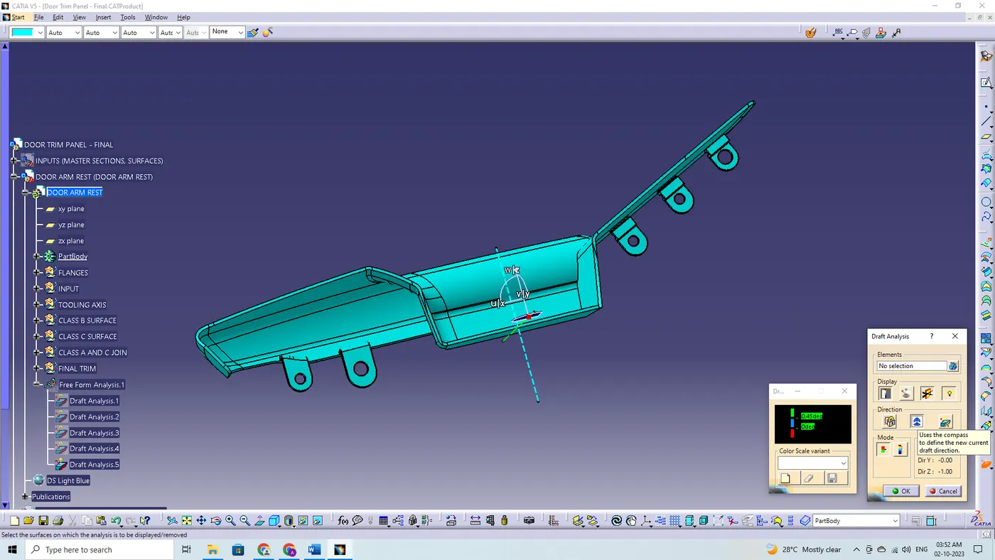
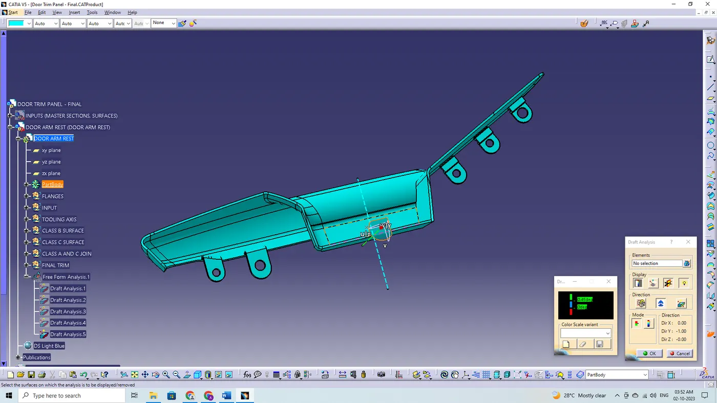
In the display window the color code variants are being selected, to know the range of the draft in the class A surface. In the display window the color variant shows,
- For 3 degree - Green color variant (Positive)
- For 0 degree - Blue color variant
- For <0>
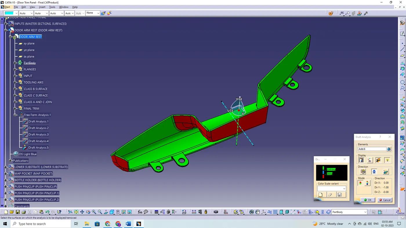
By using the side core axis, the compass is being placed on the axis to analyze draft on 0.5 degree on flange faces which are clearing on the side core tooling axis.
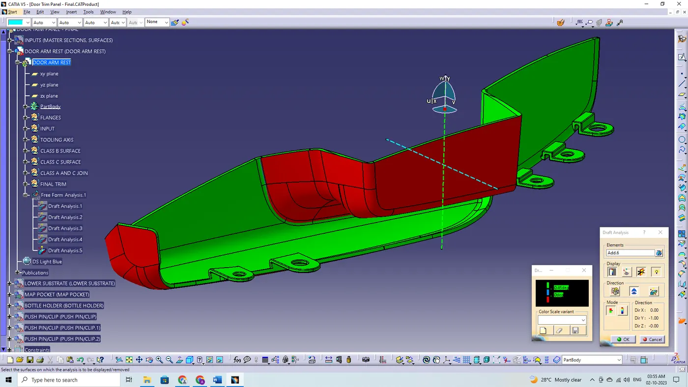
Therefore, likewise we have to make flanges for two components. i.e., Map Pocket and Bottle Holder
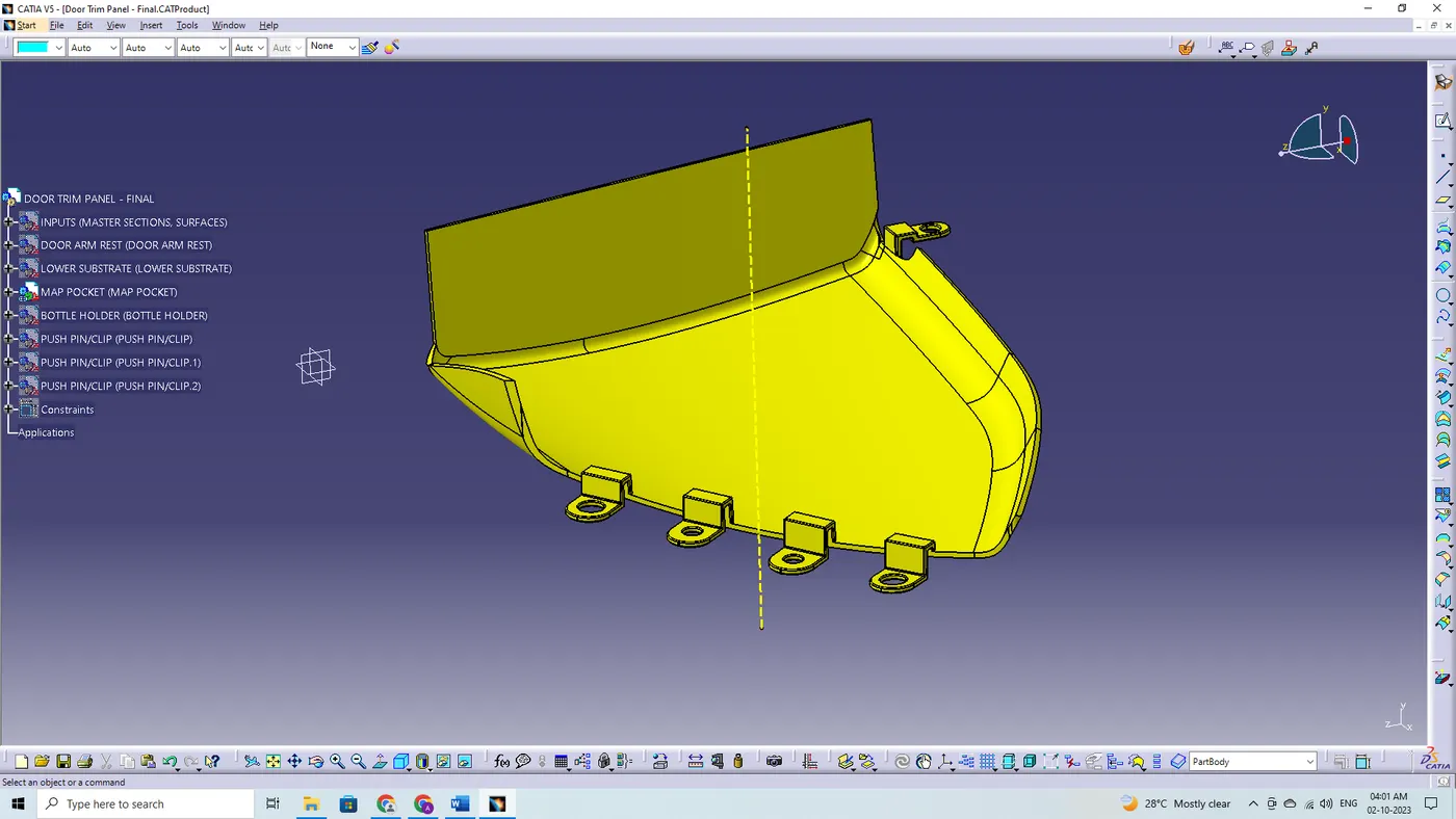
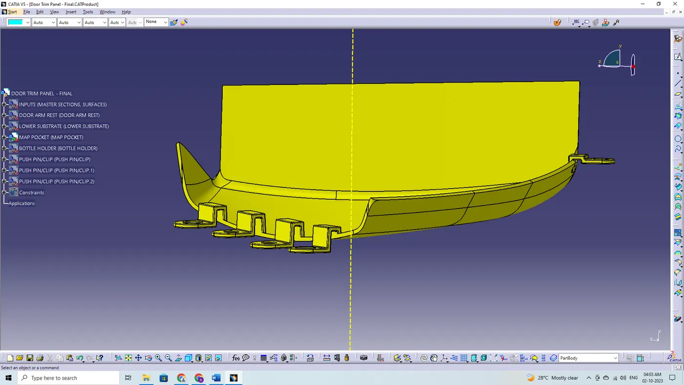
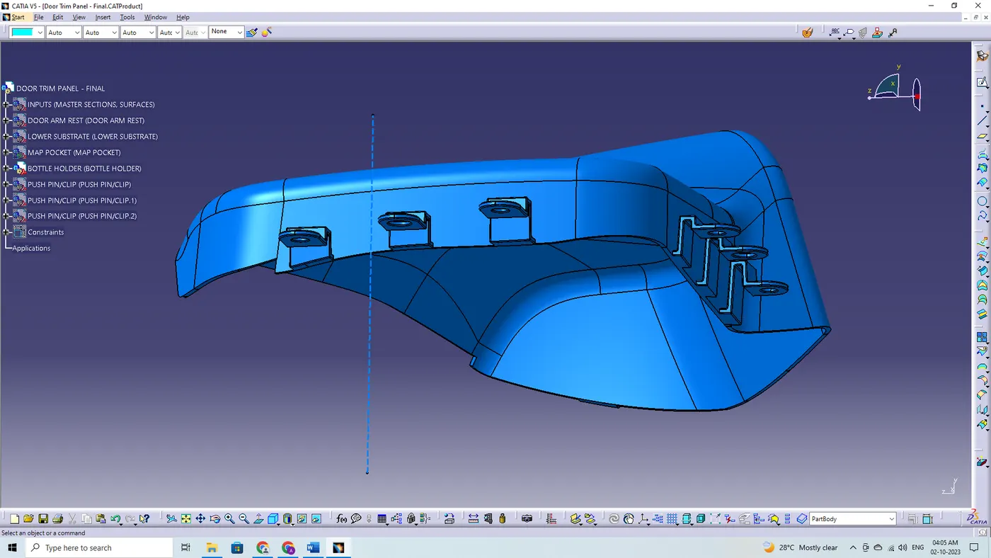
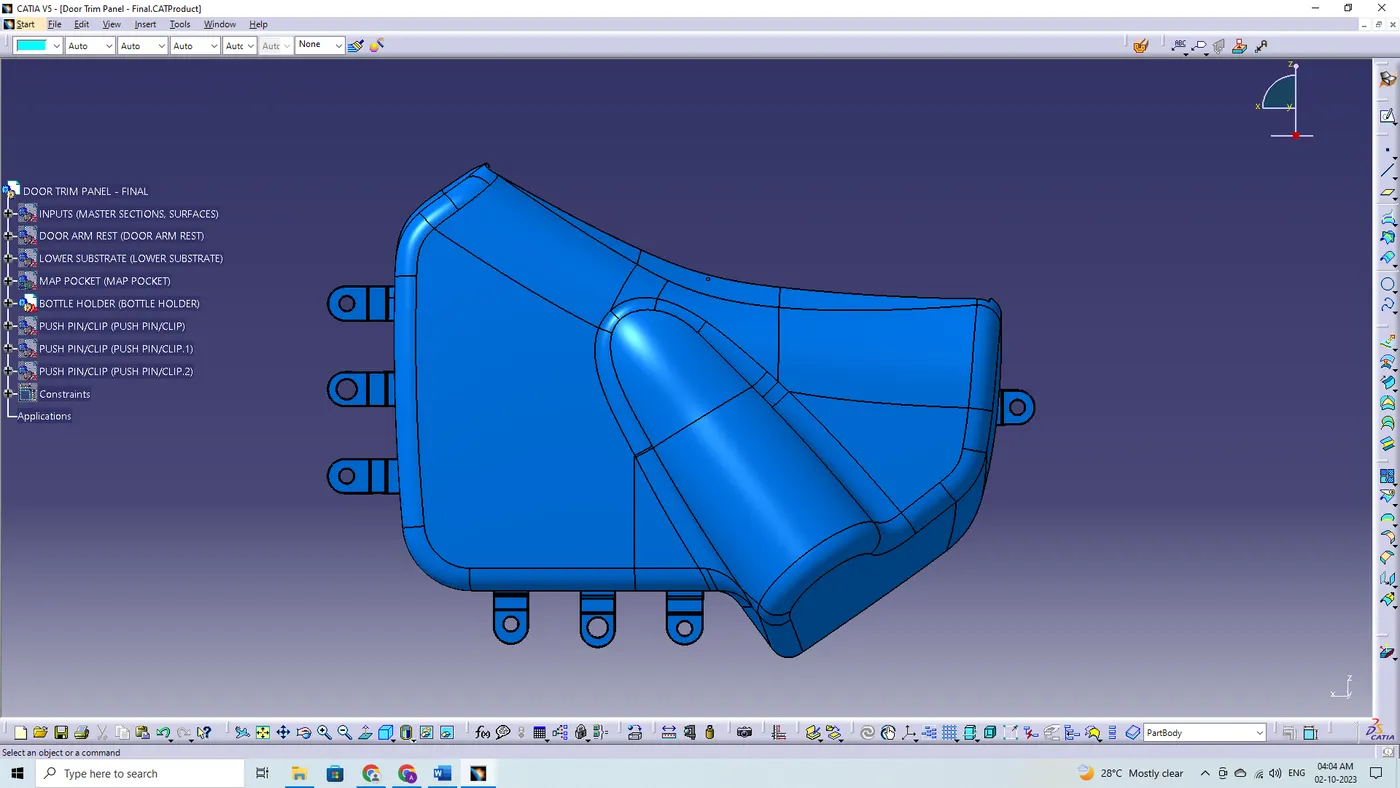
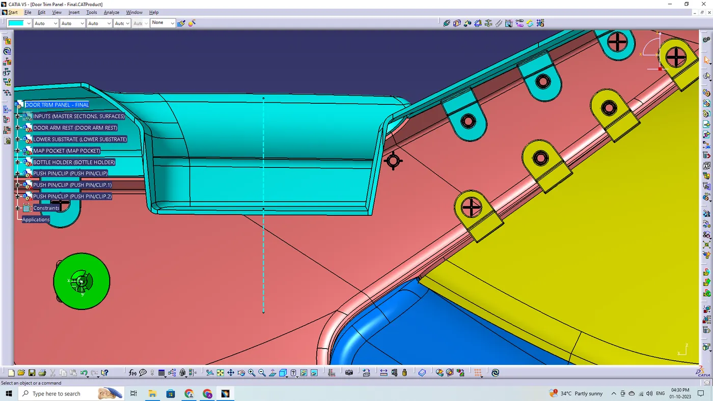
PUSH PIN/CLIP:
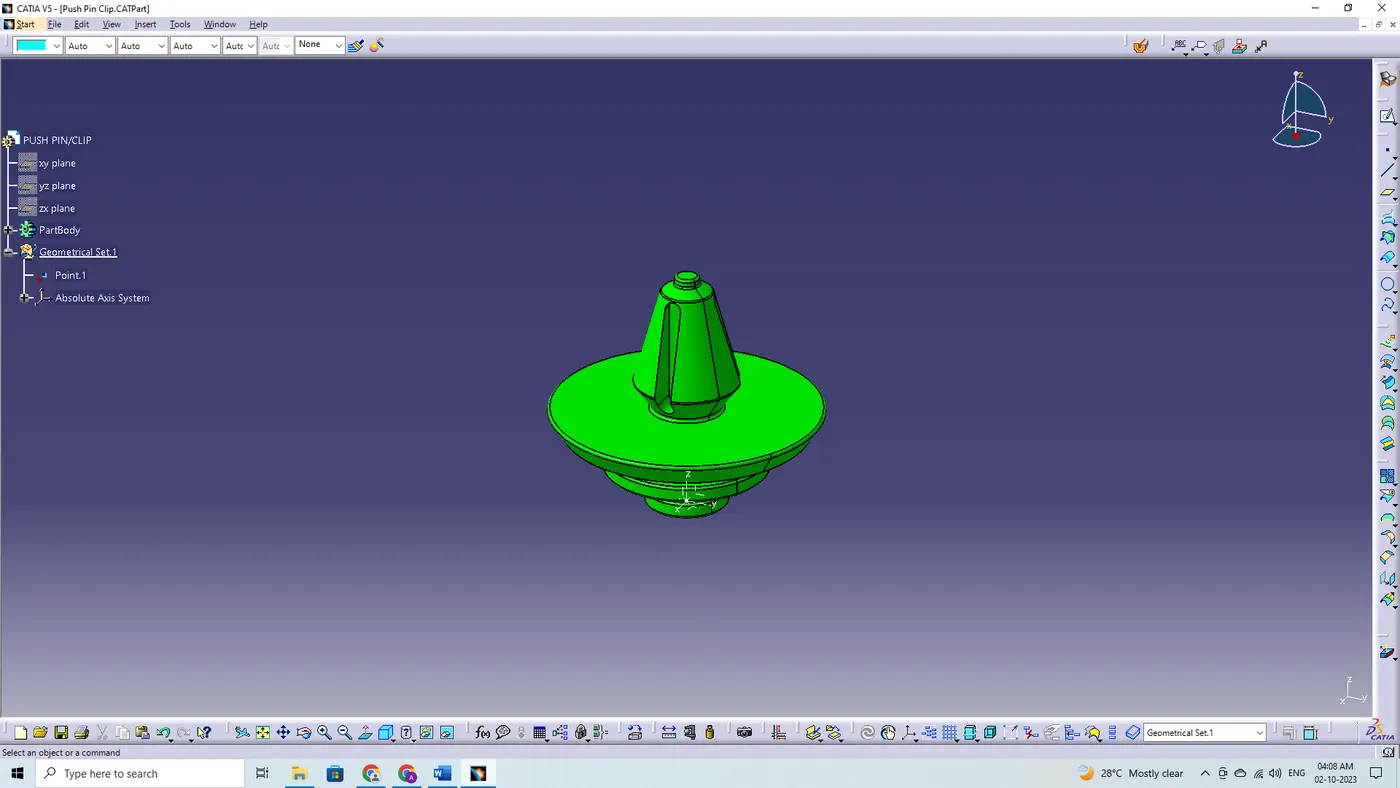
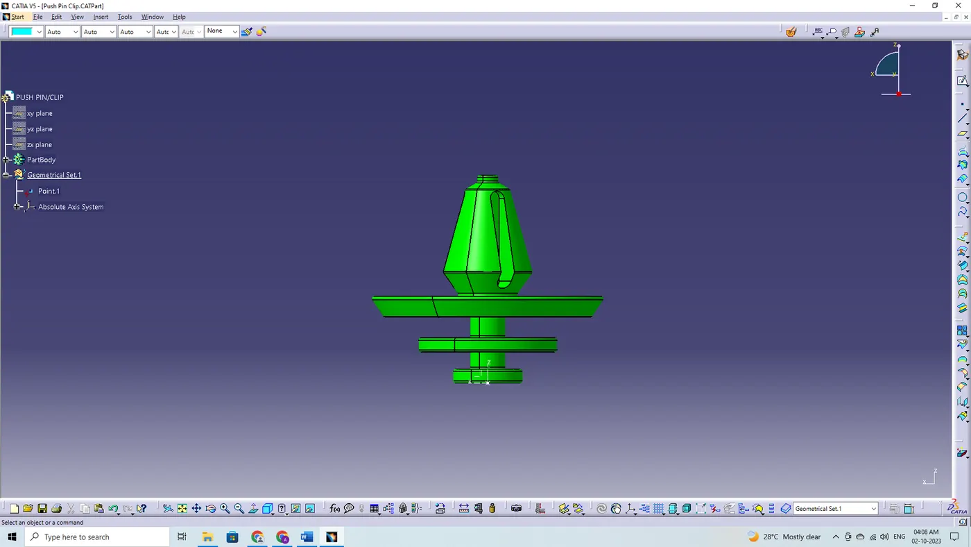
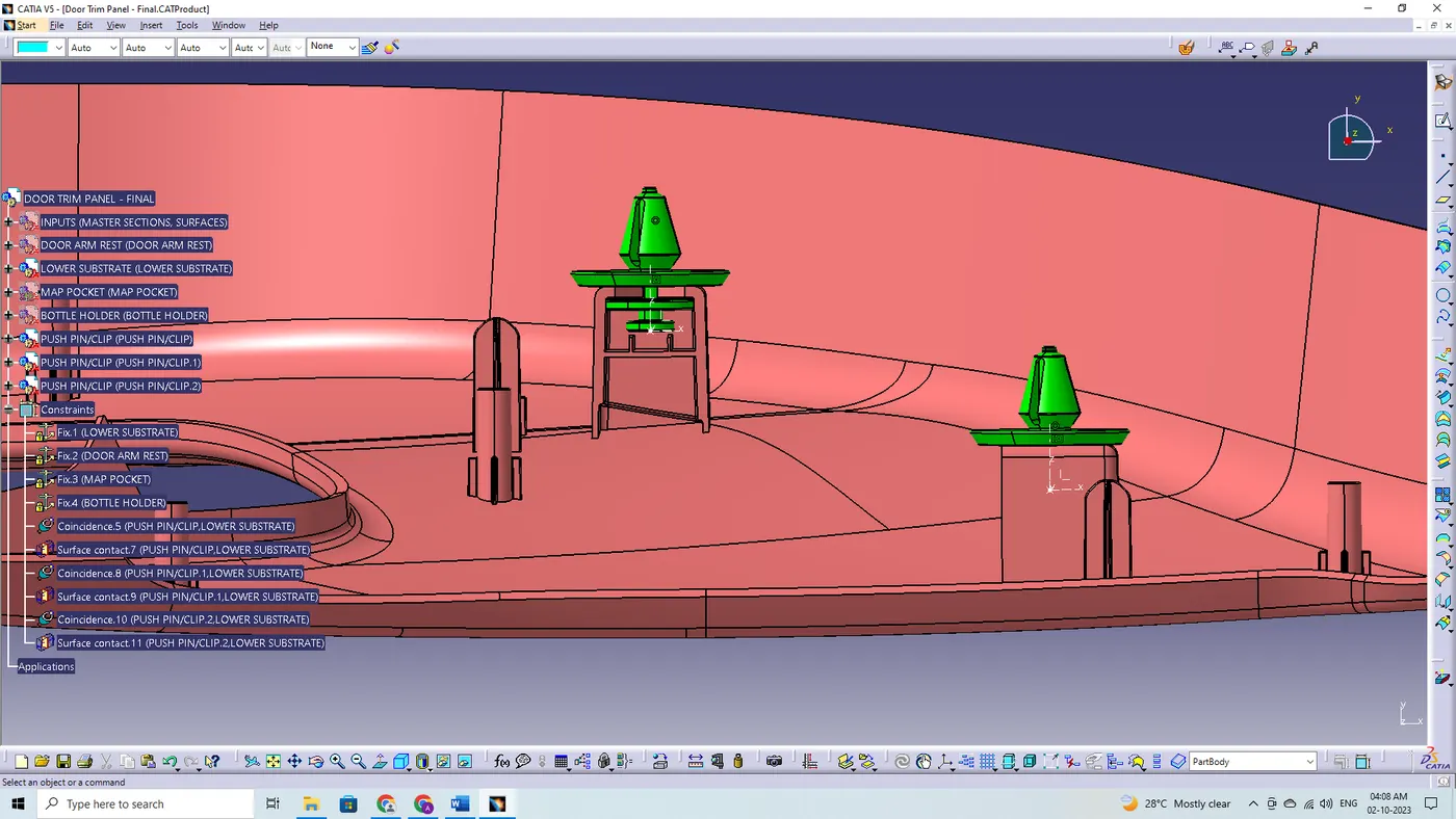
FINAL PRODUCT:
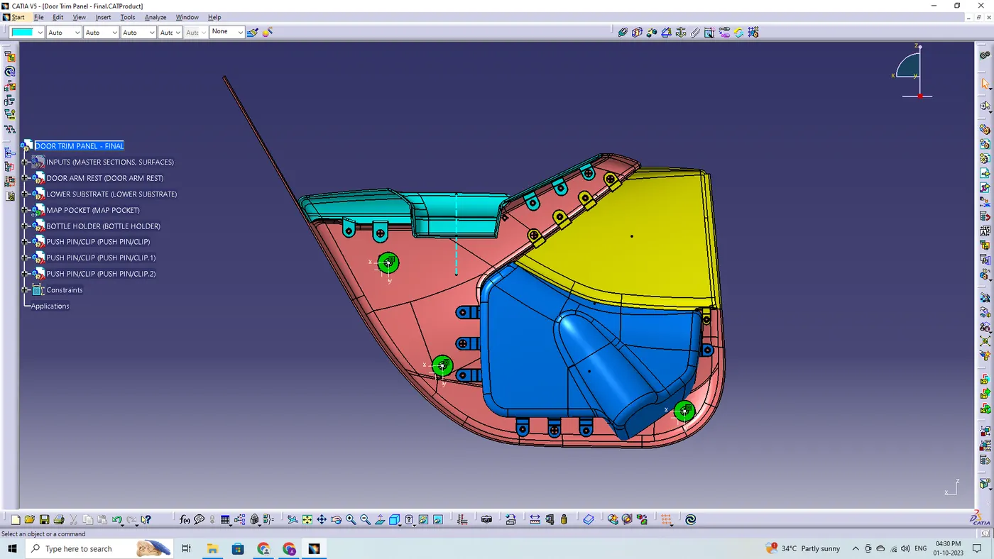
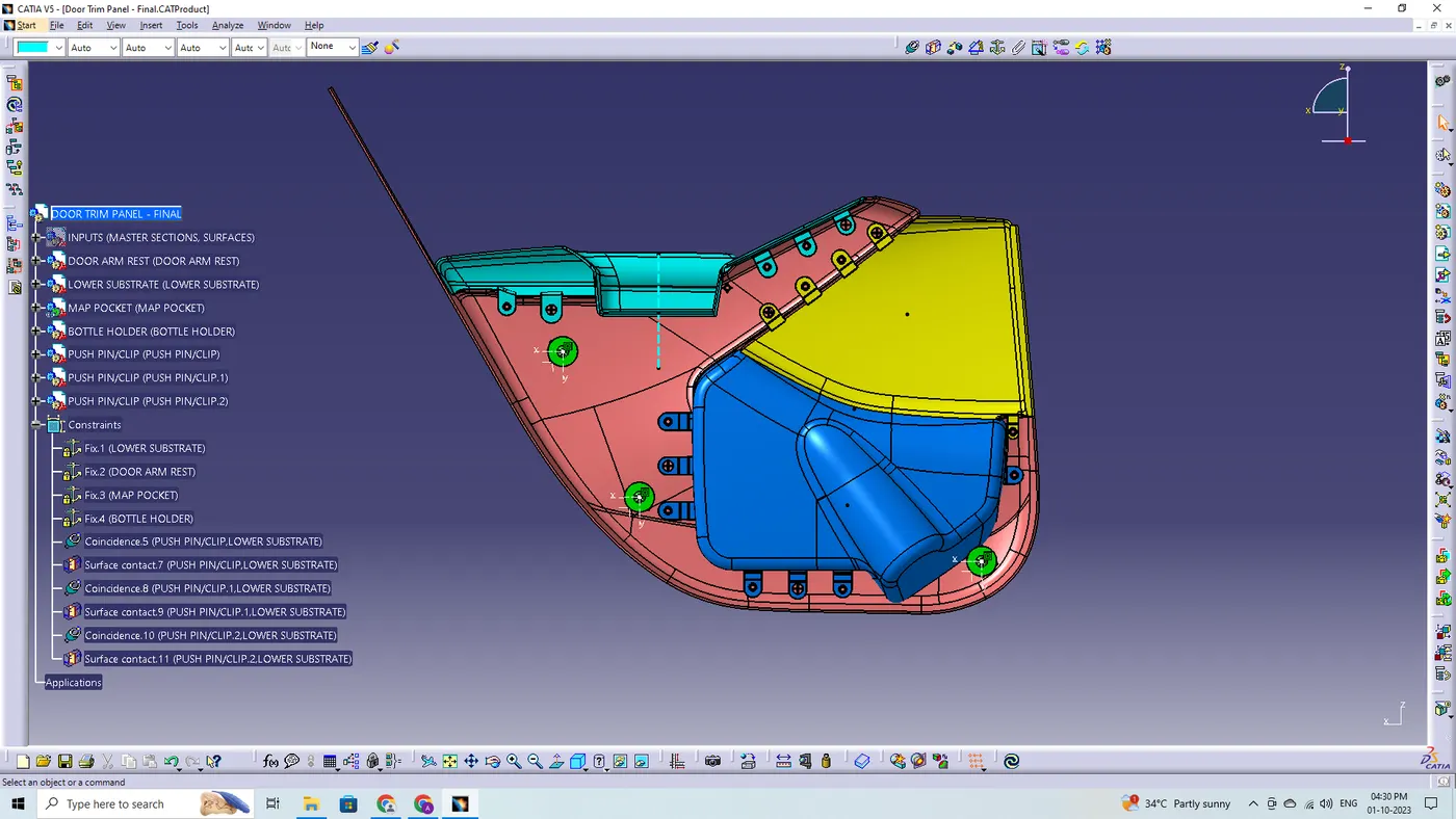
Tree- Structure for Constraints:
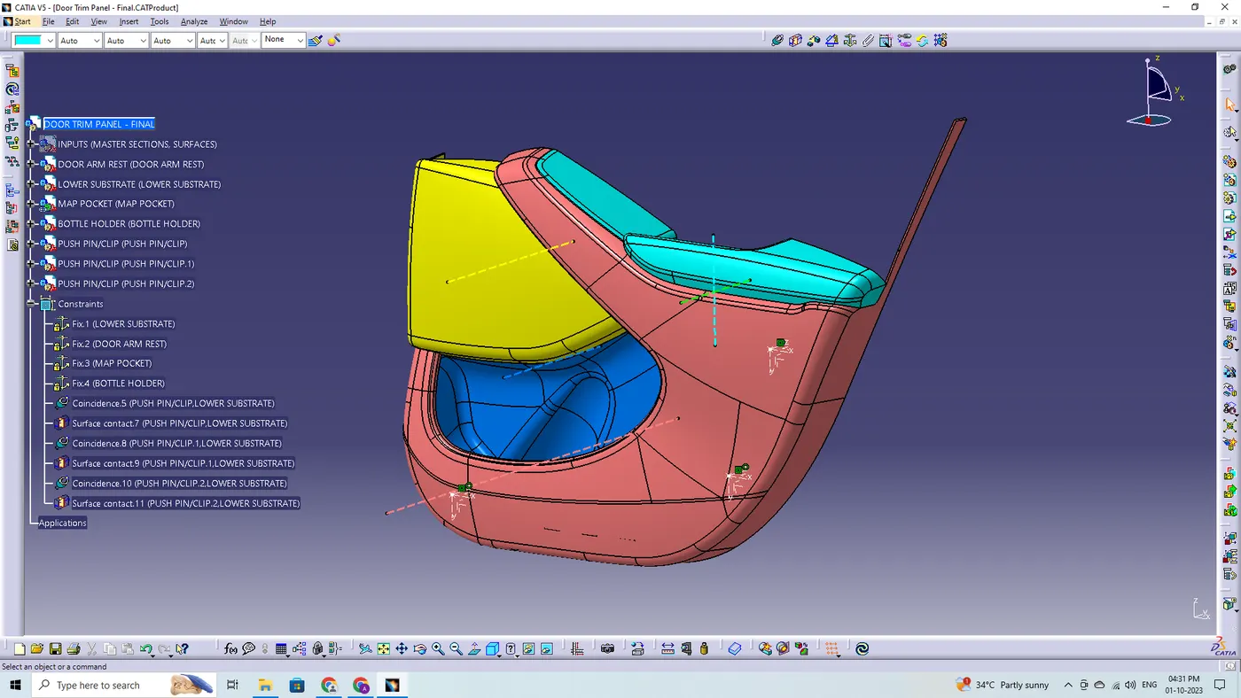
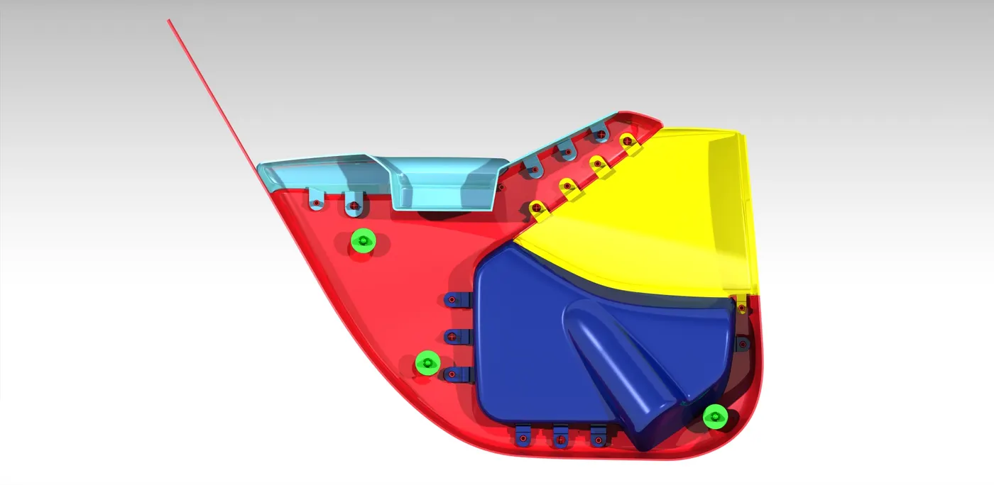
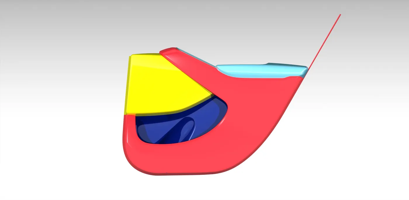
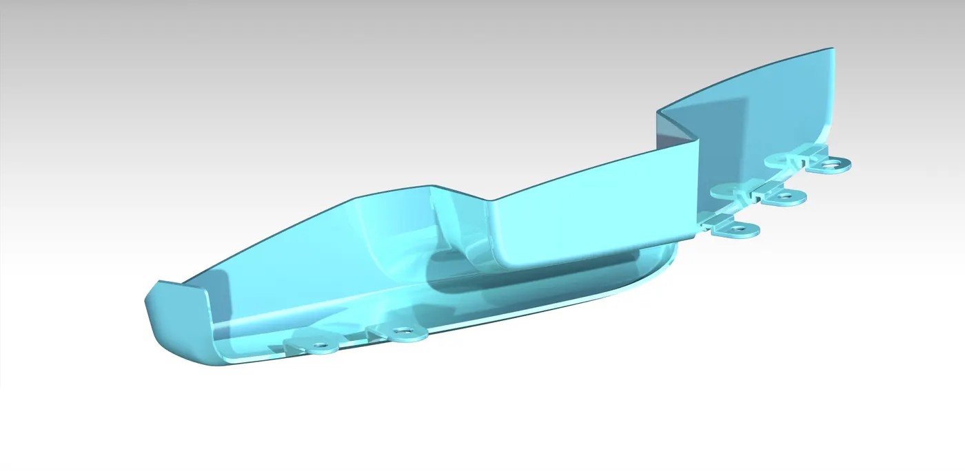
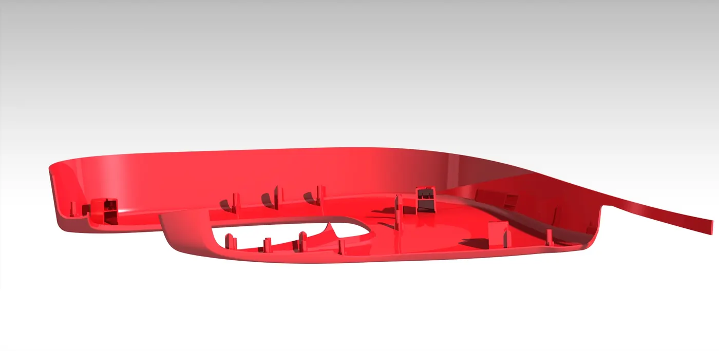
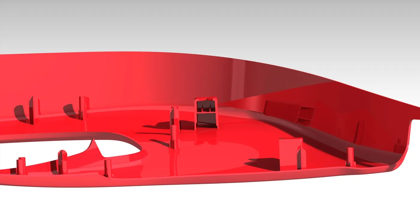
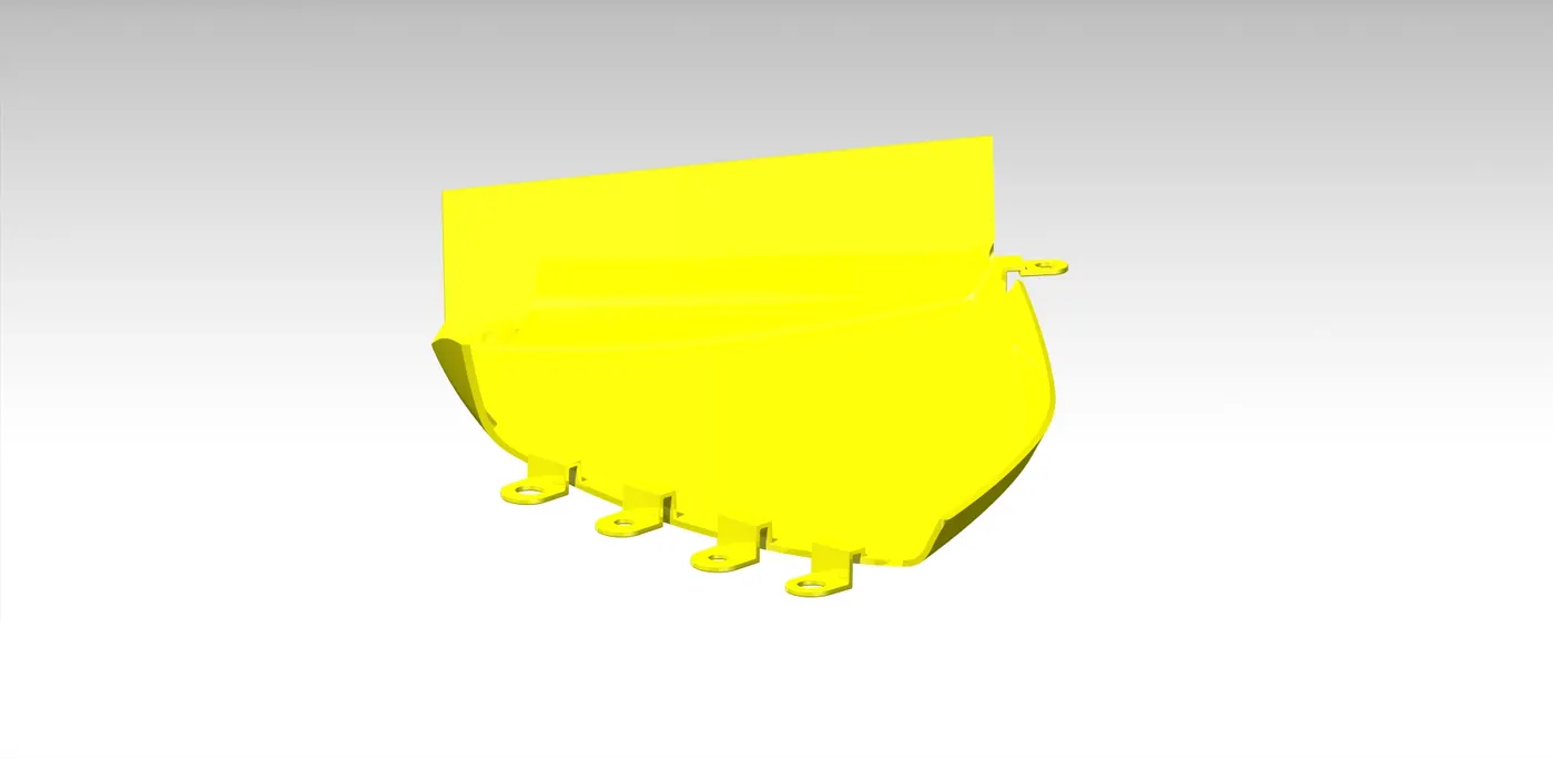
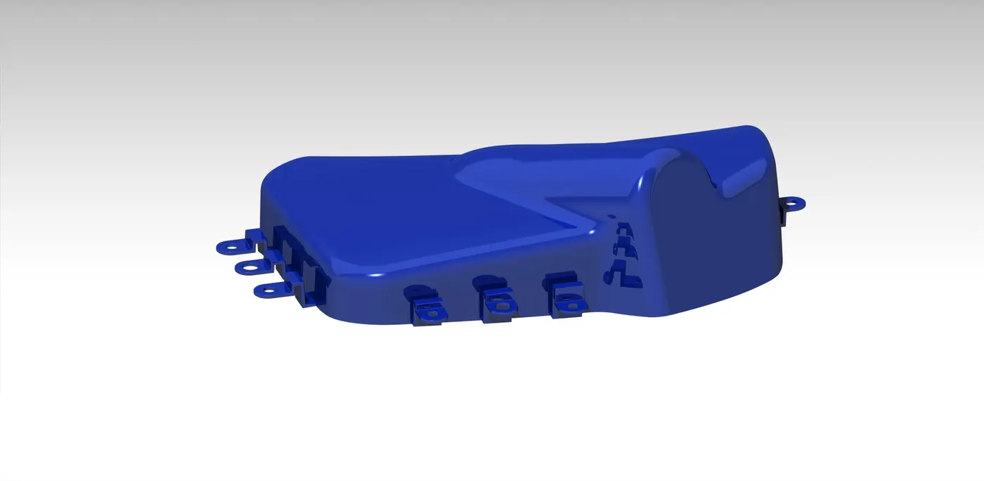
KEYSHOT RENDERING:
NOTE:
I let slip to delete/remove one heatstake completely from the component.
Reason: as the heatstaking process will be difficult at the placed area.