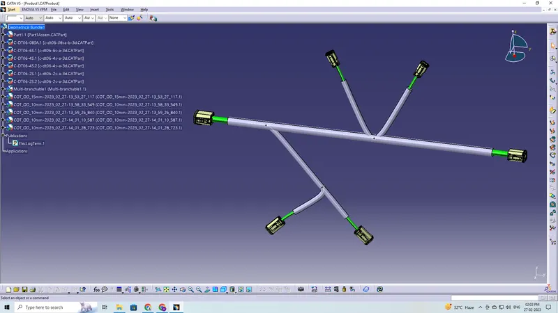
Wiring harness design in CATIA V5 - 3D modeling Week 4 Challenge
Q1. Route the following harness layout in Electrical workbench. Make assumption for harness bundle diameters. Use Following connectors as shown in layout diagram.
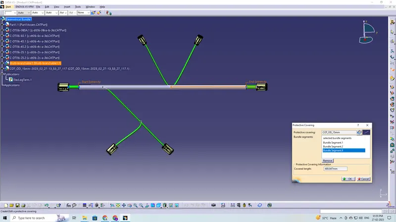
Add protective covering on all branches connected to DT06-2S & DT06-4S connectors. Keep end extremity at 30mm (from connectors end)
Download connector 3D data from www.te.com
- DT06-4S
- DT06-6S
- DT06-2S
- DT06-08SA
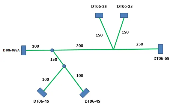
The objective of this project is to first, download the given files from TE.com then define them as an electrical connector or equipment and give all the required electrical properties to them using the electrical part design workbench and lastly route the following harness layout in electrical workbench on CATIA V5.
These are the steps required to do in this project-
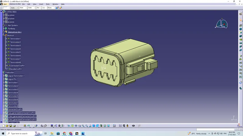
- Create the required geometrical parameters for connector
- Create a bundle entry point
- Define part as a connector
- Create bundle connection point
- Create a connector connection point
- Saving the connector in catalogue
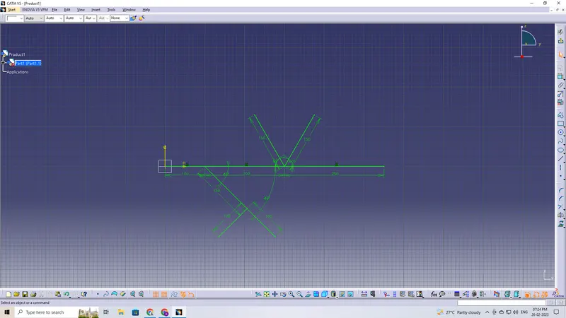
- A sketch created on a plane with dimensions appropriate for the dimensions of the entire harness assembly
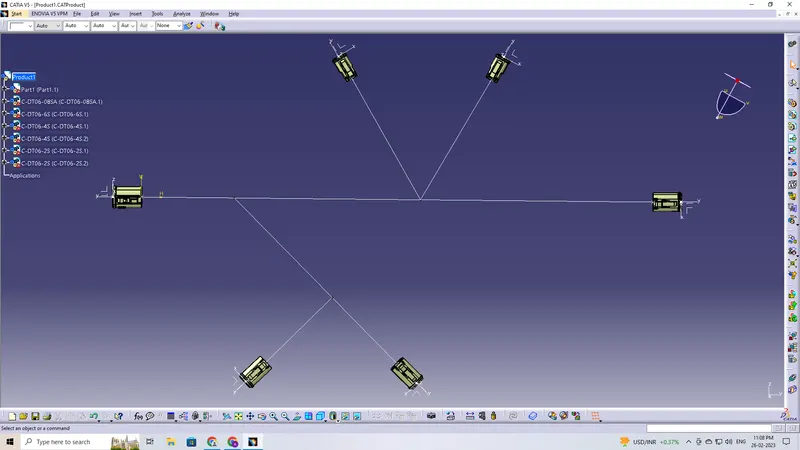
- The connectors are moved and oriented on the sketch according to the requirements
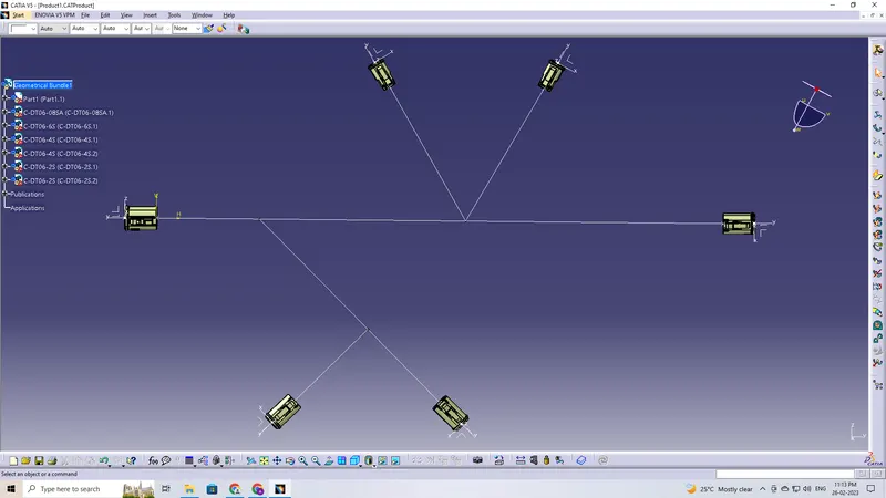
- Defining the Geometric Bundle
- Creating Multi-Branchable, Branch Points and Connections
The given components are as follows:
- DT06-4S
- DT06-6S
- DT06-2S
- DT06-08SA
DT06-4S
Defining the Geometrical Parameter to the part
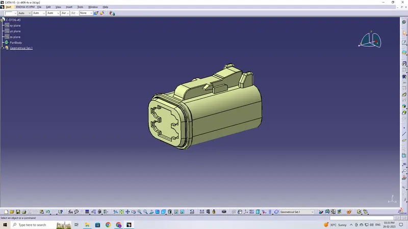
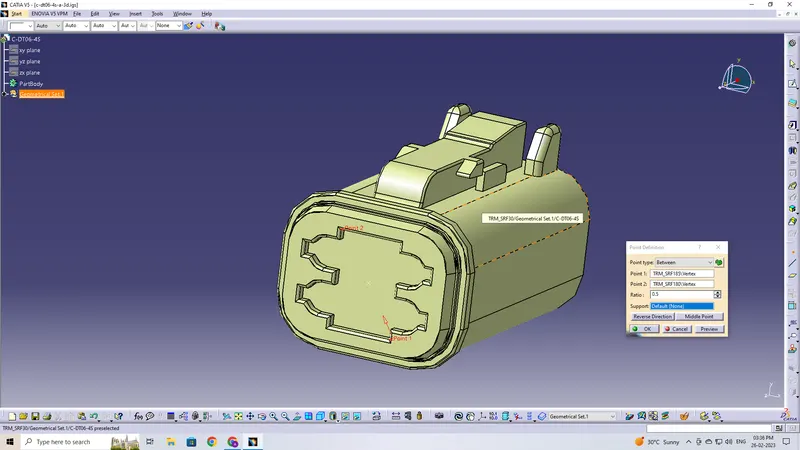
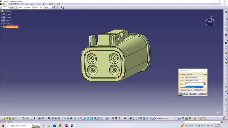
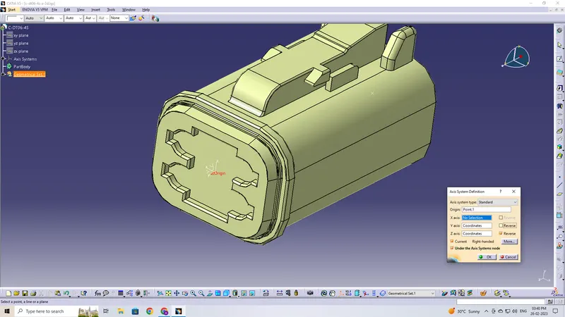
Defining part as a Connector
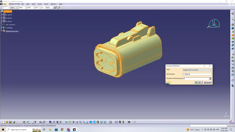
Defining Bundle Connection Point
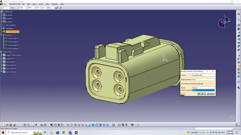
Defining Connector Connection Point
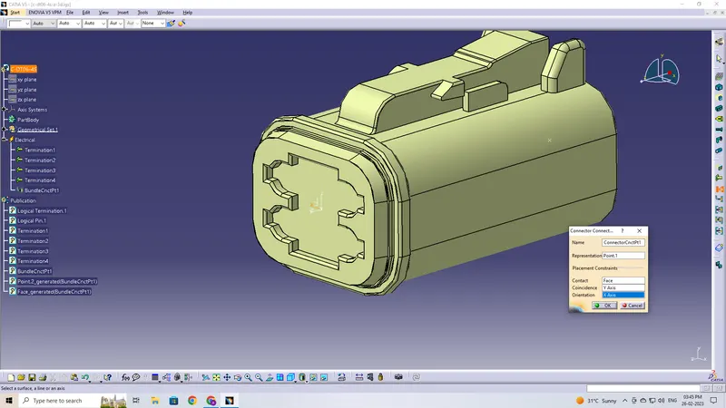
Saving the Connector in Catalogue
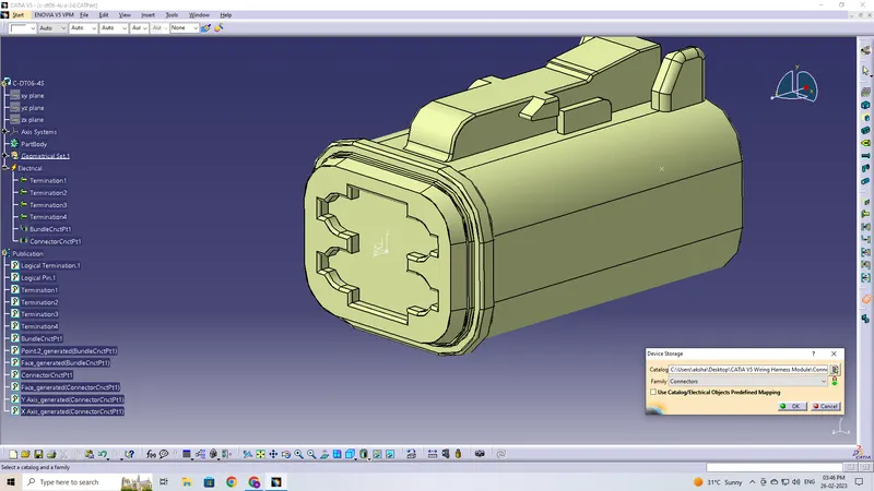
Likewise the same is done for the remaining connectors
DT06-2S
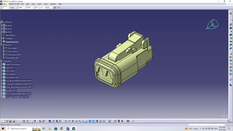
DT06-6S
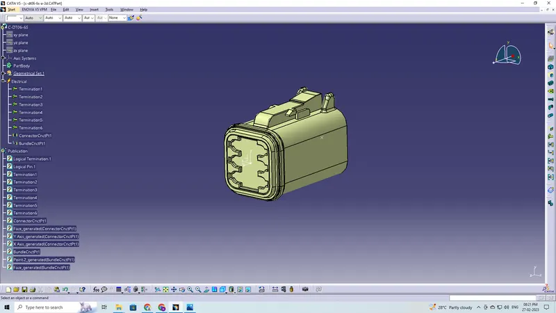
DT06-08SA
A sketch created on a plane with dimensions appropriate for the dimensions of the entire harness assembly
The connectors are moved and oriented on the sketch according to the requirements
Defining the Geometric Bundle
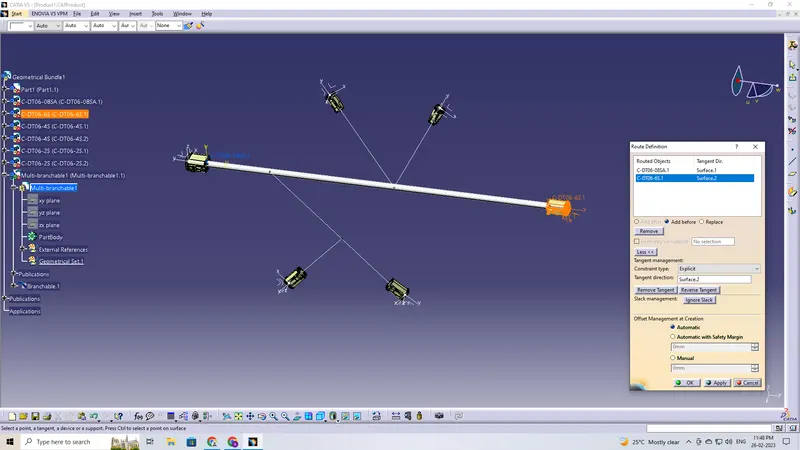
Creating Multi-Branchable, Branch Points and Connections
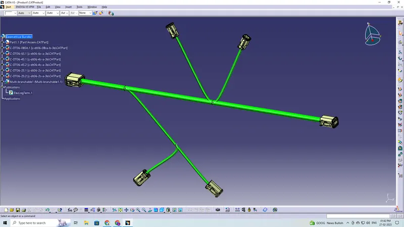
Corrugated Tube Protective Covering is applied
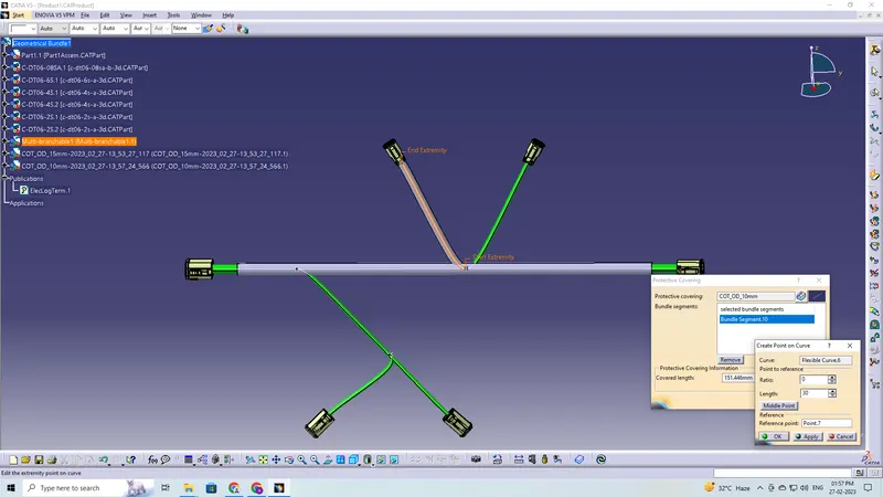
Final Wiring Harness