Wiring harness design in CATIA V5 - 3D modeling Week 5 & 6 Challenge
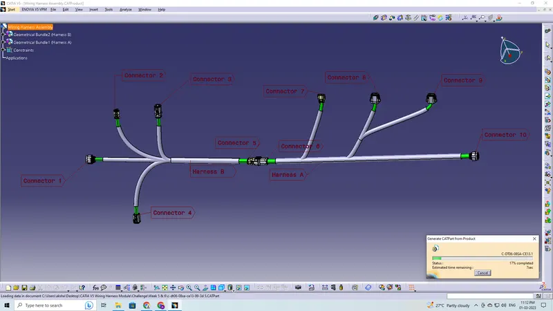
Q1. Route the following harness layout in Electrical workbench. Make assumption for harness bundle diameters. Use the connectors provided. After completion of routing,
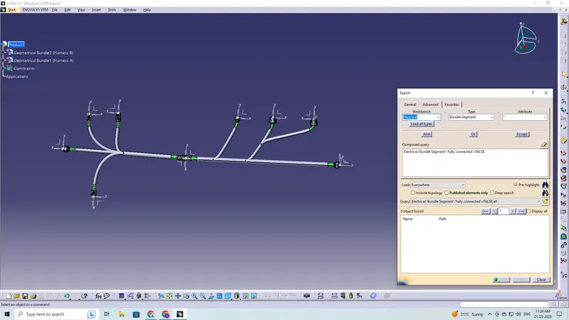
- Check the bundle Continuity. Add snap of result in submission
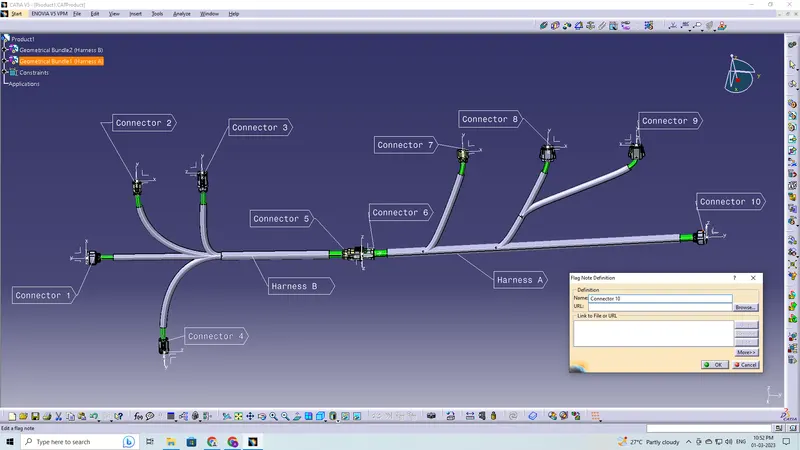
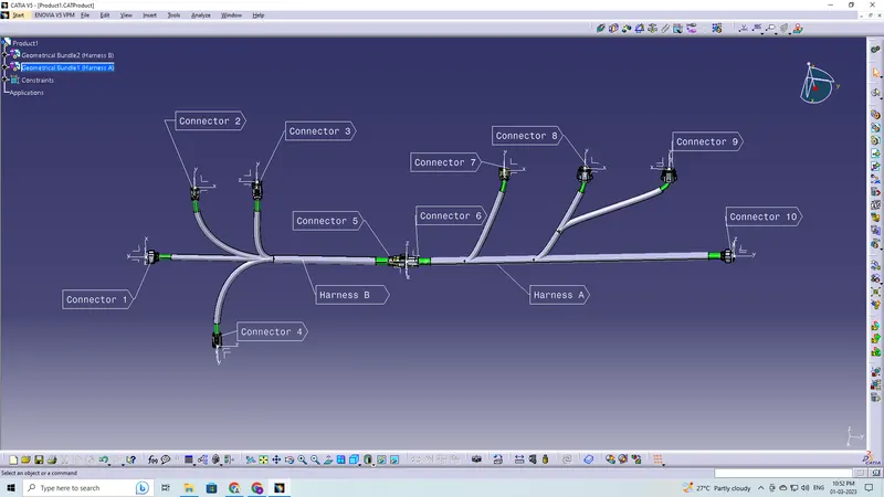
- Add annotation to all connectors. Make an assumptions for annotations like connect 1 , 2 etc
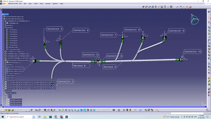
- Check for the bundle warning. Add snap.
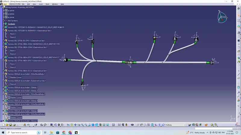
- Generate CAT.part of harness assembly and convert is in. igs format.
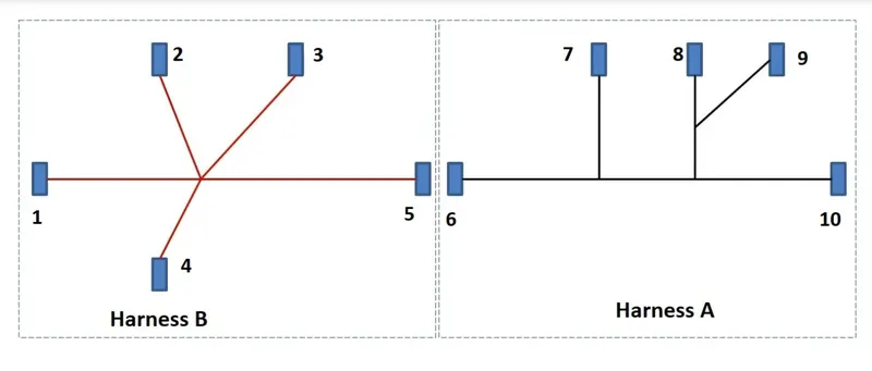
The objective of this project is to first, download the given files from TE.com then define them as an electrical connector or equipment and give all the required electrical properties to them using the electrical part design workbench and lastly route the following harness layout in electrical workbench on CATIA V5.
These are the steps required to do in this project-
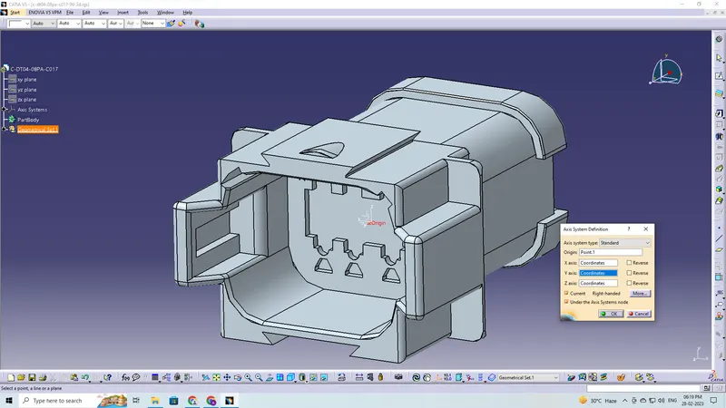
- Create the required geometrical parameters for connector
- Create a bundle entry point
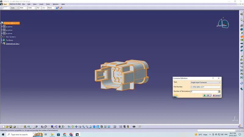
- Define part as a connector
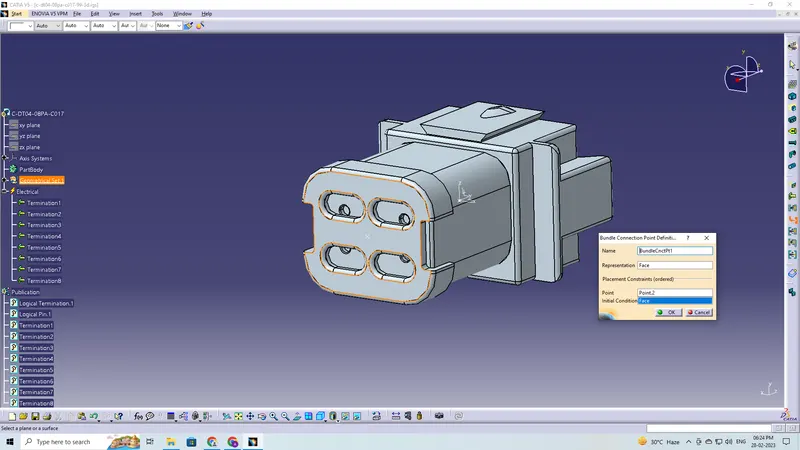
- Create bundle connection point
- Create a connector connection point
- Saving the connector in catalogue
- The connectors are placed in their proper positions as given in the task.
- The connectors are moved and oriented according to the given requirements.
- Defining the Geometric Bundle
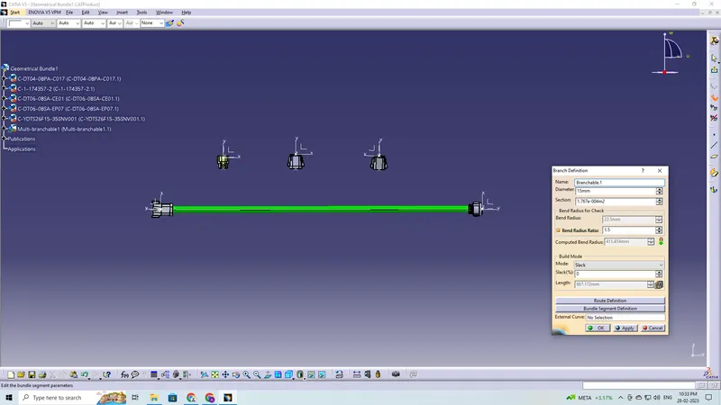
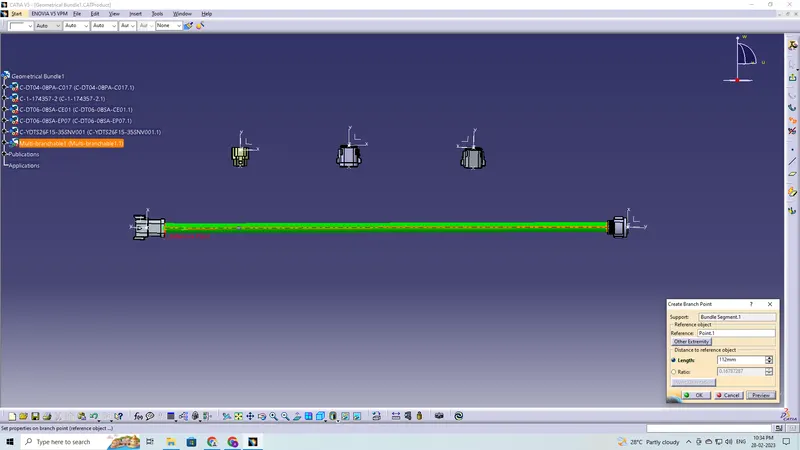
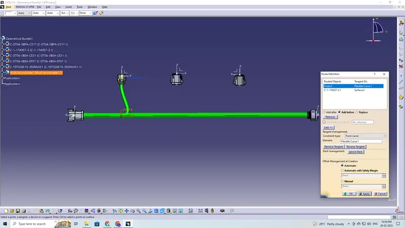
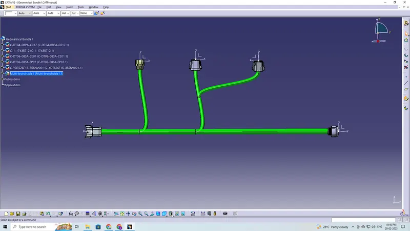
- Creating Multi-Branchable, Branch Points and Connections
The given components are as follows:
Harness A
- C-DT04-08PA-C017
- C-1-174357-2-E-3D
- C-DT06-08SA-CE01-99-3D
- C-DT06-08SA-EP07-99-3D
- C-YDTS26F15-35SNV001-99-3D
Harness B
- C-YDTS26F15-35SNV001-99-3D
- C-DT06-3S-CP01-99-3D
- C-DT06-08SA-CE04-99-3D
- C-DT06-08SA-EP07-99-3D
- C-DT06-08SA-CE13-99-3D
Harness A
C-DT04-08PA-C017
Defining the Geometrical Parameter to the part
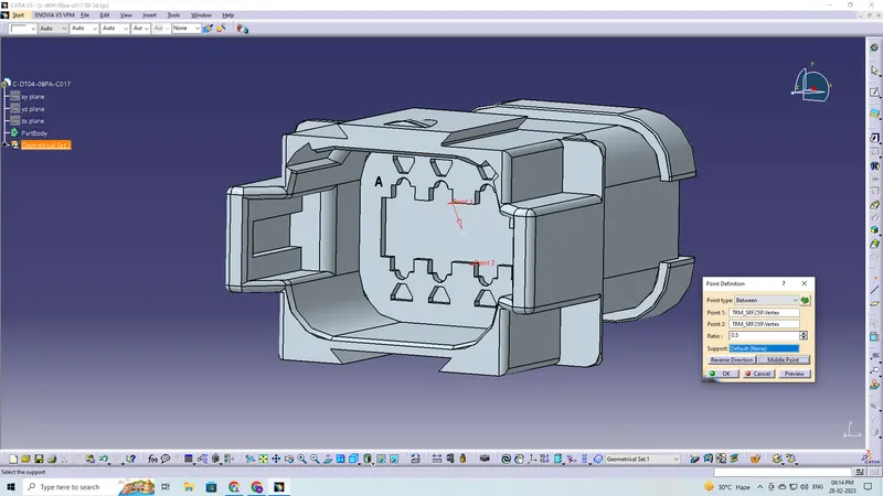
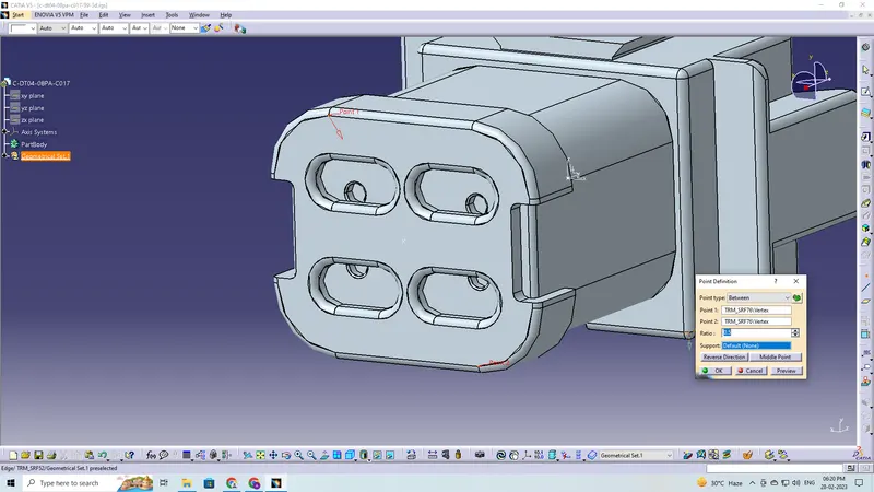
Defining part as a Connector
Defining Bundle Connection Point
Defining Connector Connection Point
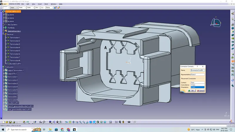
Saving the Connector in Catalogue
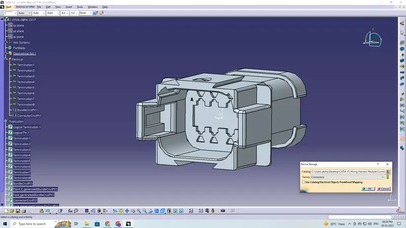
Likewise the same is done for the remaining connectors
C-1-174357-2-E-3D
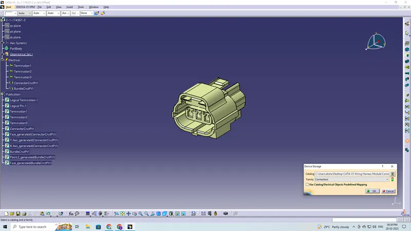
C-DT06-08SA-CE01-99-3D
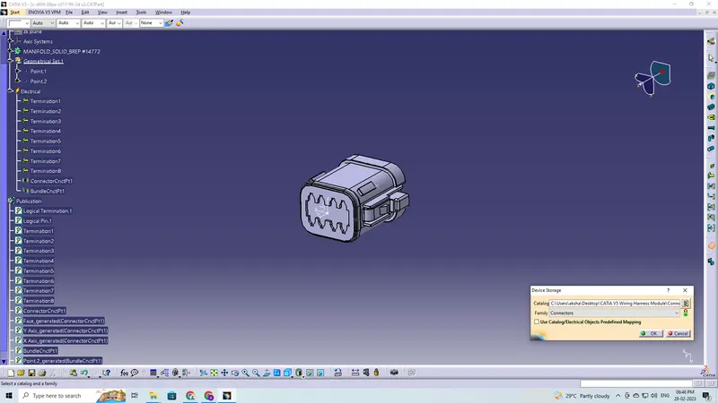
C-DT06-08SA-EP07-99-3D
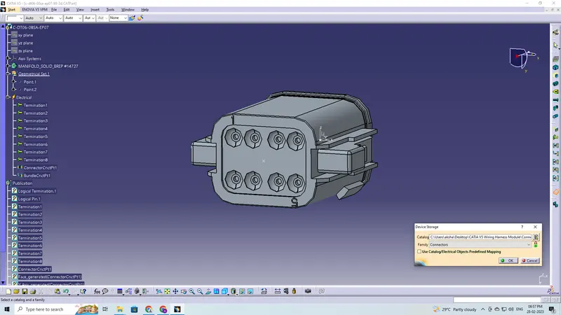
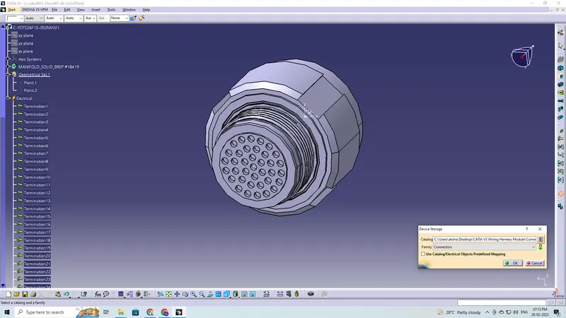
C-YDTS26F15-35SNV001-99-3D
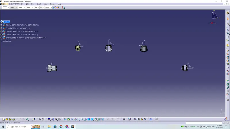
The connectors are placed in their proper positions as given in the task
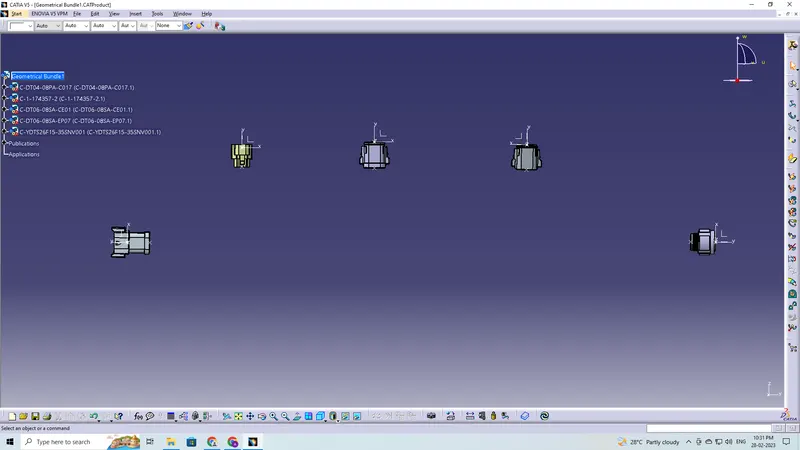
Defining the Geometric Bundle
Creating Multi-Branchable, Branch Points and Connections
Corrugated Tube Protective Covering is applied
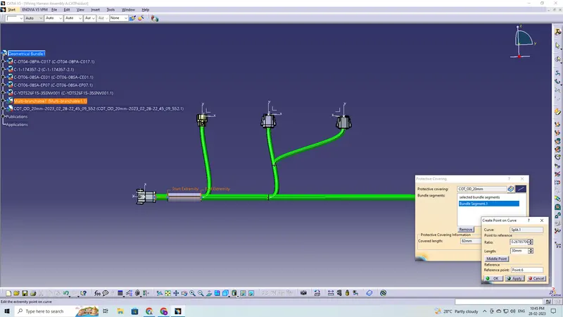
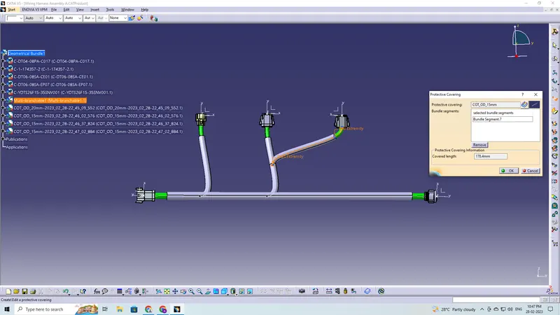
Final Wiring Harness
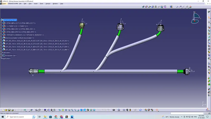
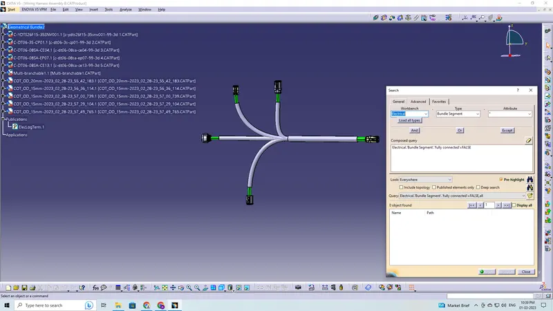
Check the bundle Continuity
There is no discontinuity in the Harness A
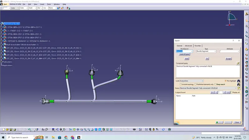
Harness B
C-YDTS26F15-35SNV001-99-3D
C-DT06-3S-CP01-99-3D
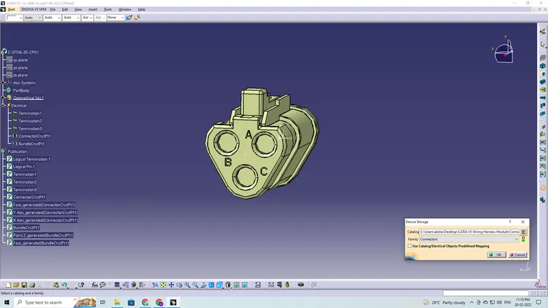
C-DT06-08SA-CE04-99-3D
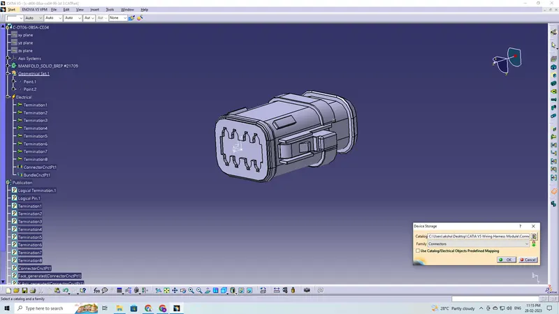
C-DT06-08SA-EP07-99-3D
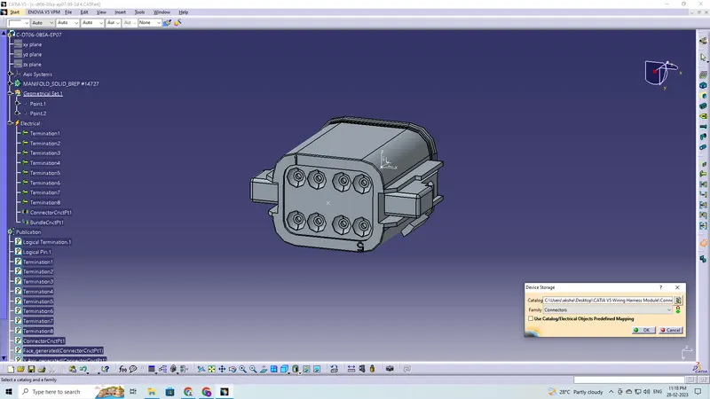
C-DT06-08SA-CE13-99-3D
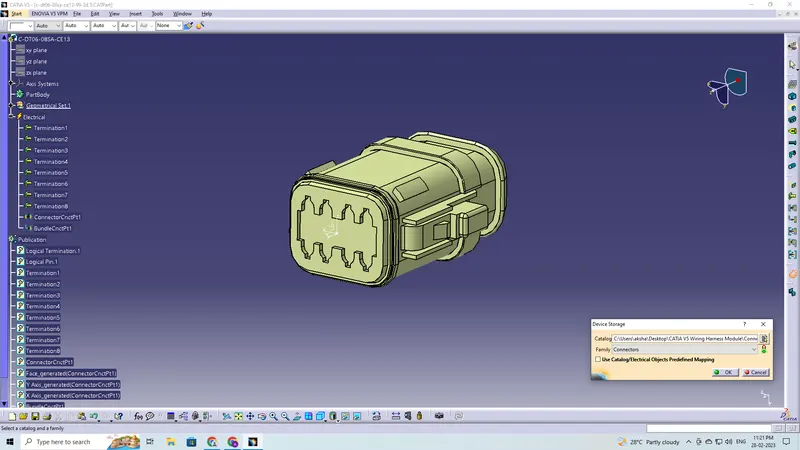
The connectors are placed in their proper positions as given in the task
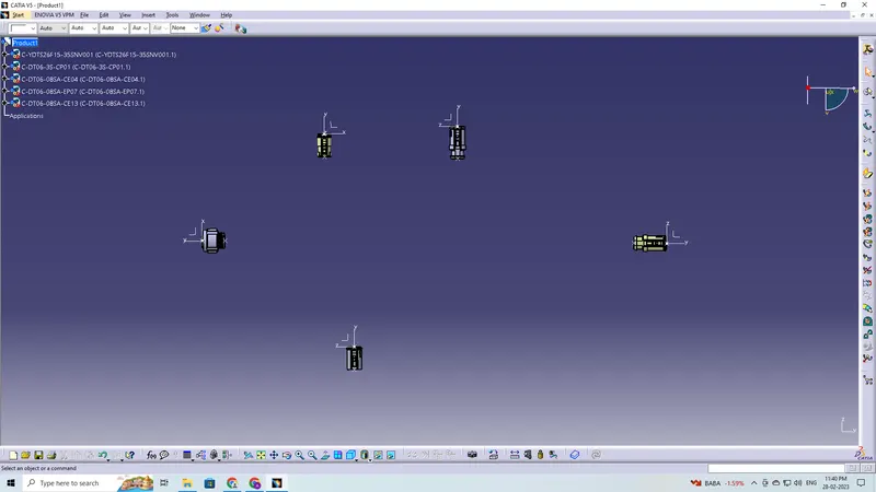
Defining the Geometric Bundle
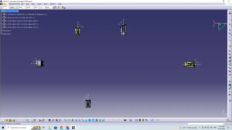
Creating Multi-Branchable, Branch Points and Connections
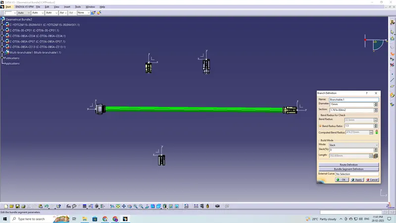
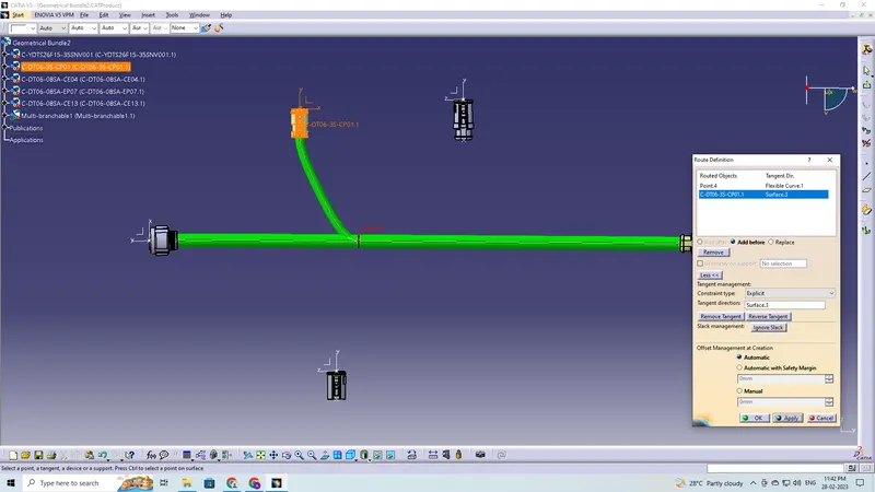
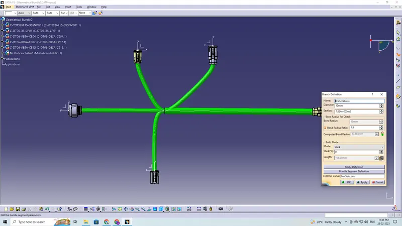
Corrugated Tube Protective Covering is applied
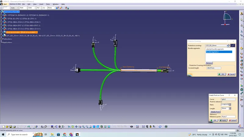
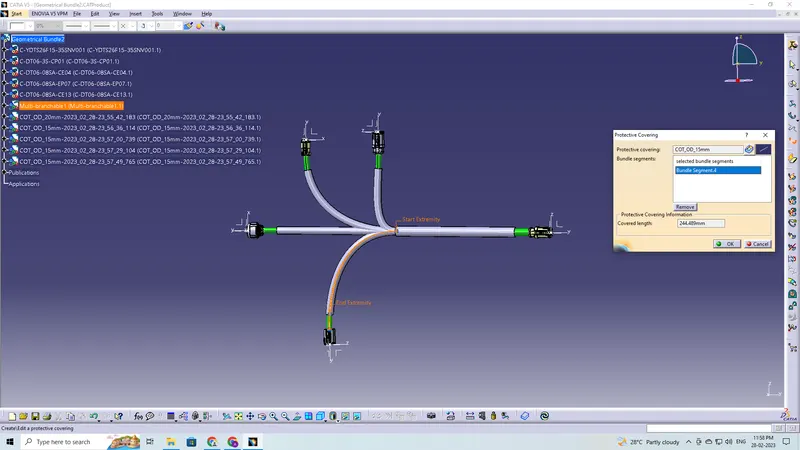
Final Wiring Harness
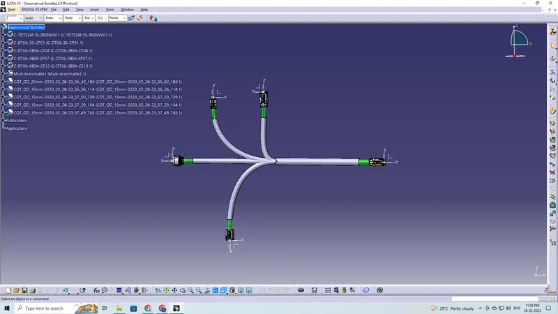
Check the bundle Continuity
There is no discontinuity in the Harness B
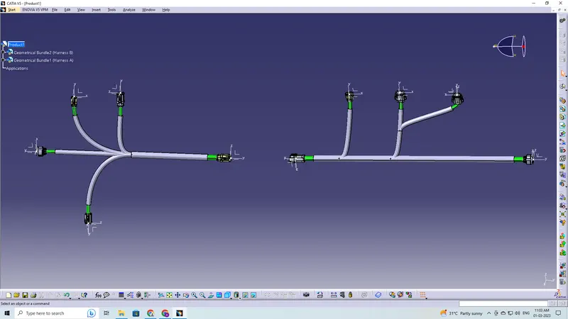
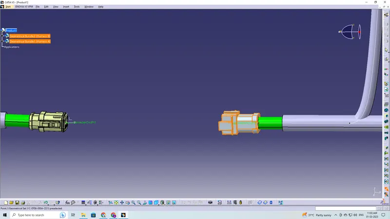
Electrically connect Wiring Harness A and Harness B
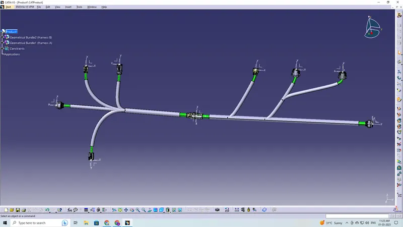
Check the bundle Continuity
There is no discontinuity along the connected harness.
Annotations
Check for the bundle warning
Harness A
Harness B
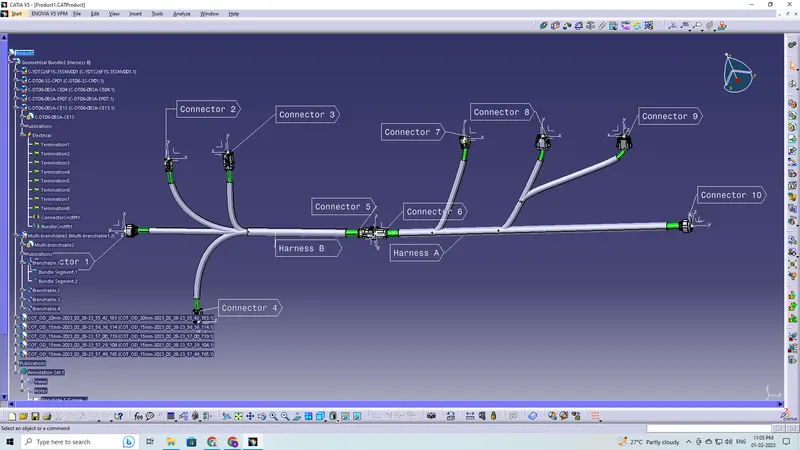
The final step is to convert our Final Harness Assembly file into IGS format