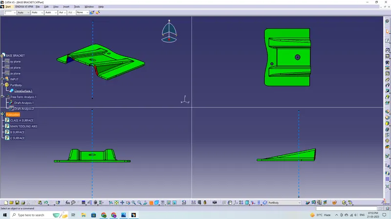
Week 9 - Challenge 1 - Base Bracket Design
Create the Base Bracket Plastic component through the given Class-A surface. To begin with, the tooling axis for the given Class-A Surface should be created meeting the requirements of the draft angle and at the end perform the Draft analysis on the model.
Thickness of Plastic Part - 2.5 mm
Tooling axis: The direction in which the mold or core and cavity opens is the tooling axis.
Step-1:
Connectivity of Class-A surface:
Creating boundaries or just utilising the join option will allow you to check the surface's connectedness while making any openings visible.
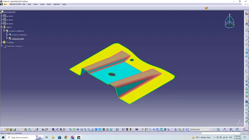
Step-2:
Find the ideal tooling axis by conducting a visual analysis.
The Point-direction command will immediately construct a Dummy tooling axis.
Checking for possibilities (clearances) in all axis directions and determining the problem-creation parts of the component or model.
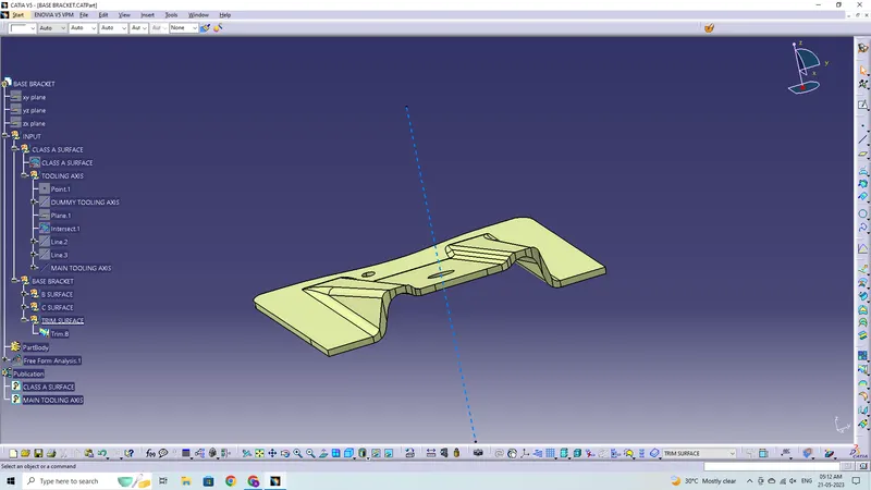
Creating an intersection along an axis on a plane with the model and building two lines that make contact with the walls will be used to check the clearance along all of the axis directions. The line that cuts through this intersection will be the tooling axis.
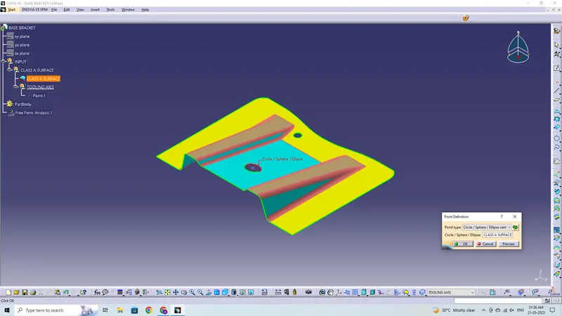
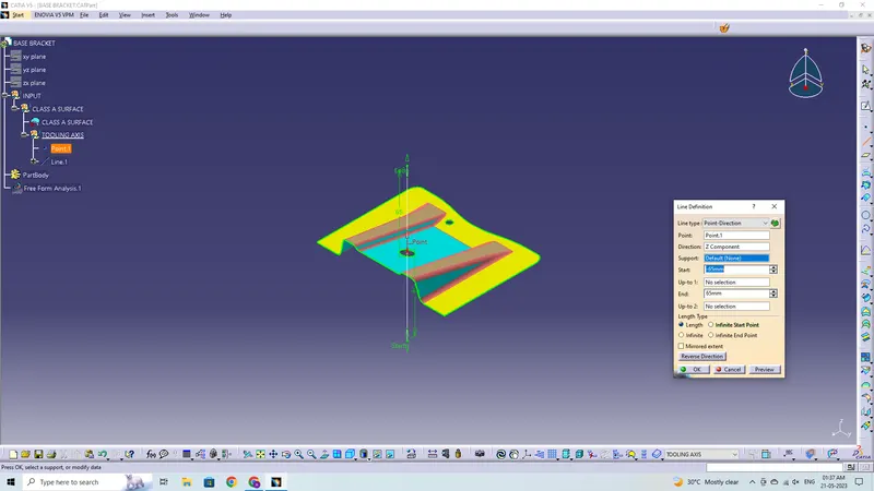
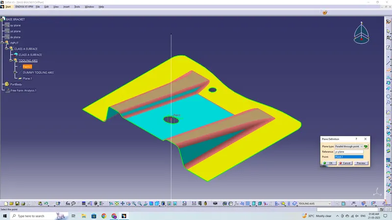
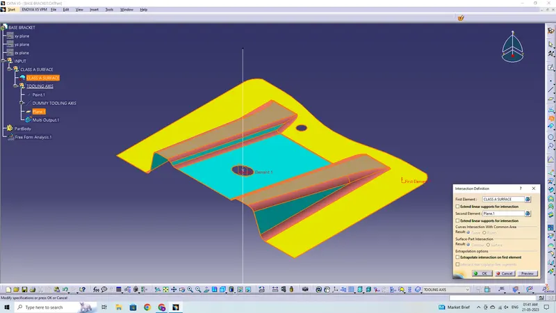
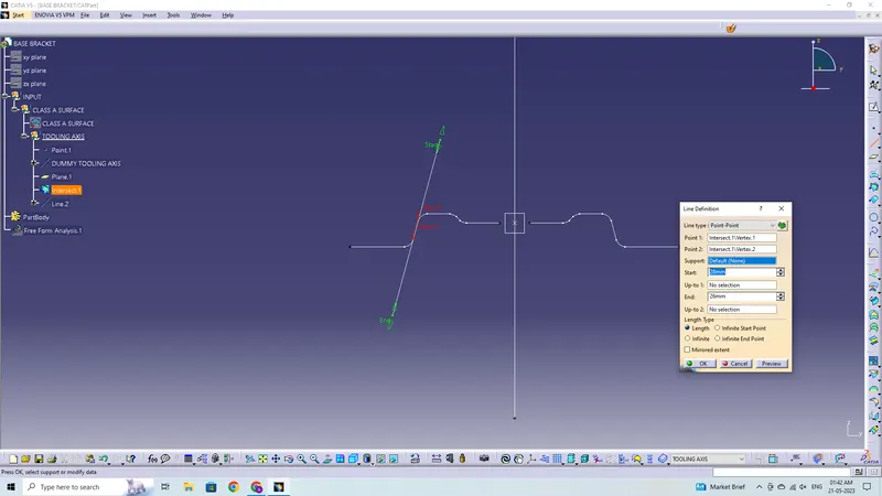
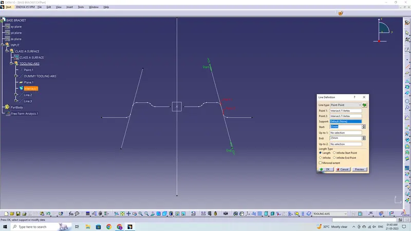
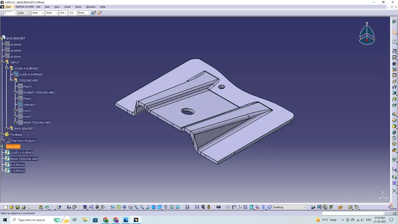
Tooling Axis Creation:
A bisecting line passing from a point to the two lines constructed with the help of walls from the intersection will be treated as the tooling axis.
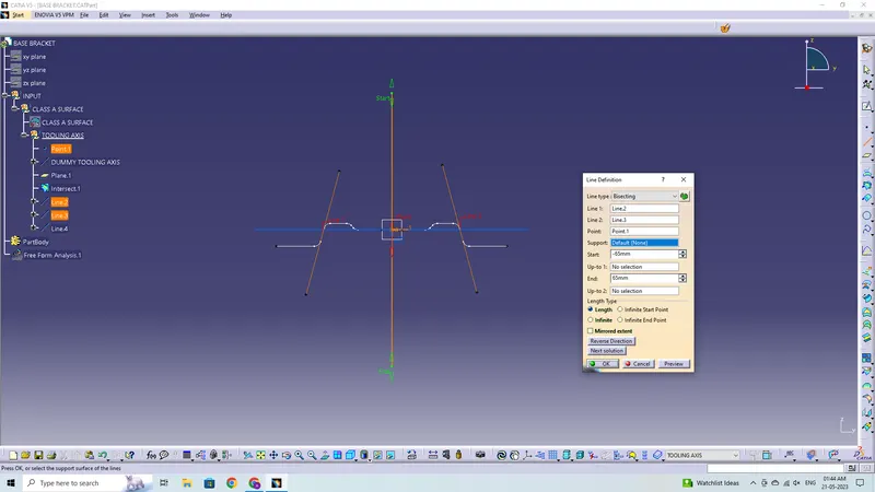
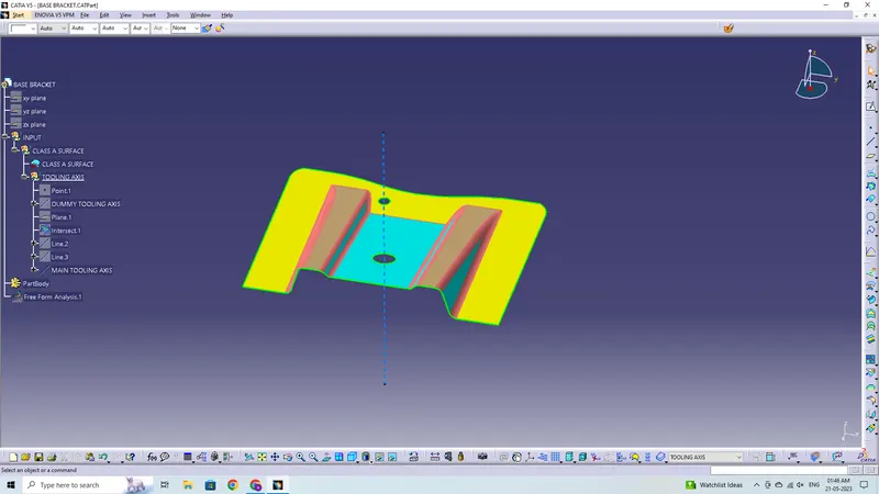
Draft Analysis for Class-A Surface:
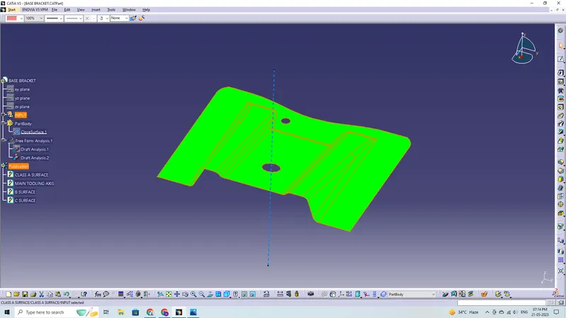
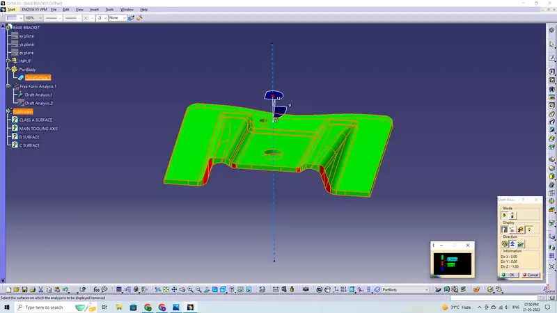
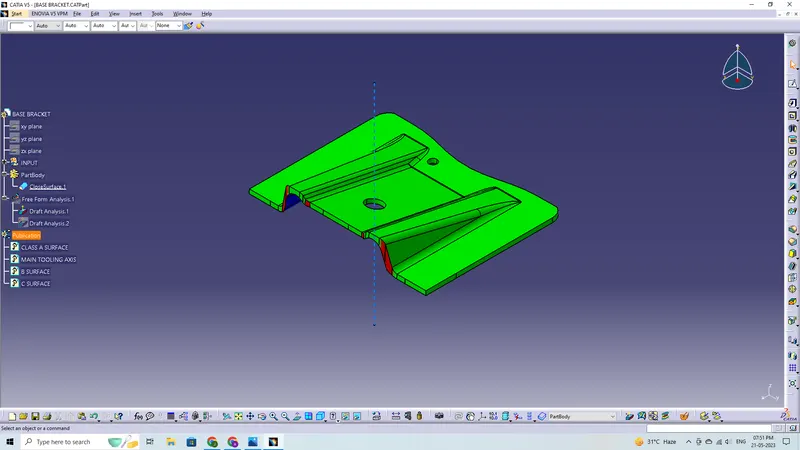
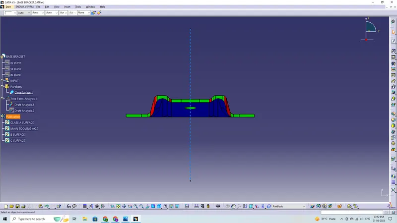
After choosing the tooling axis, draft analysis is carried out to see if the minimum draught (3 degrees) is being maintained.
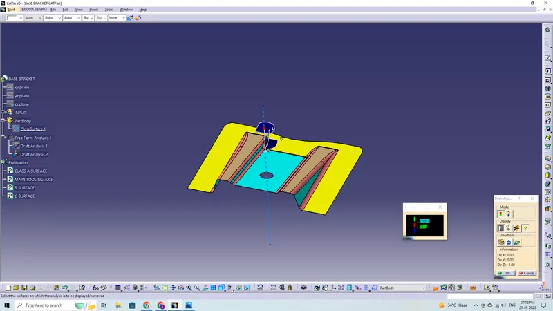
Compass is used to define the draft direction.
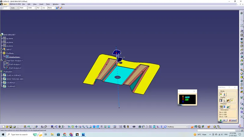
If the minimum draft 3 degree is provided the whole component changes in to green colour.
Class-B Surface:
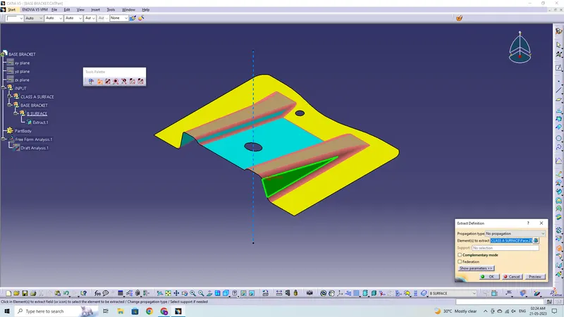
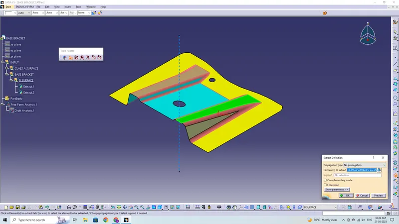
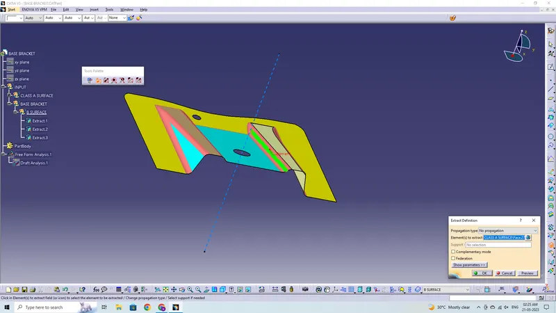
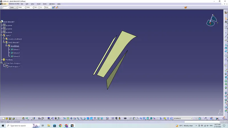
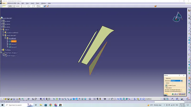
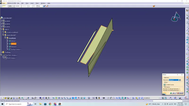
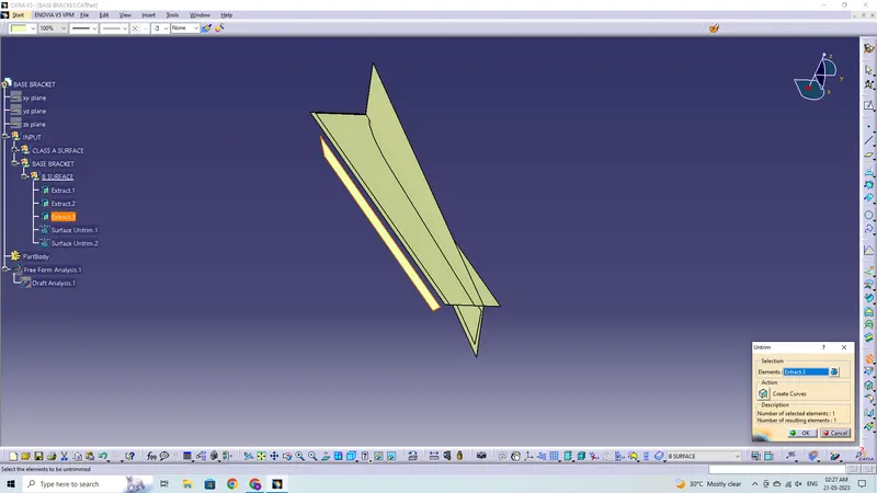
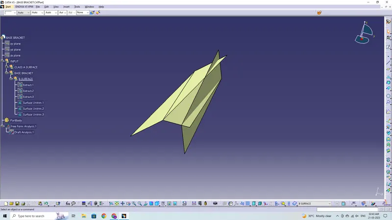
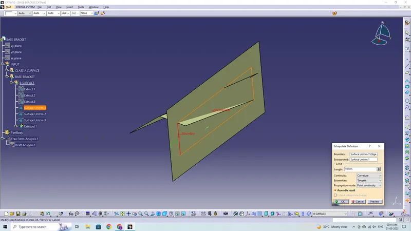
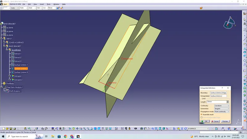
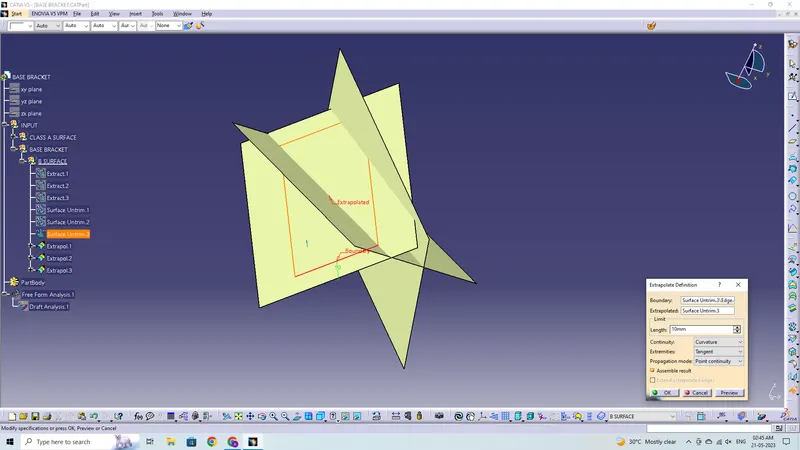
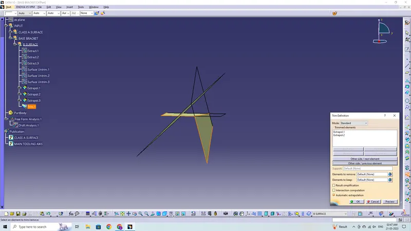
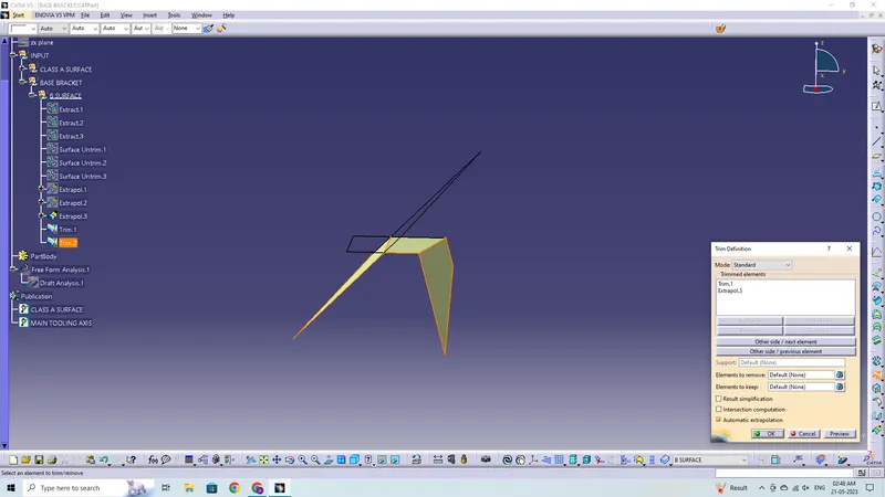
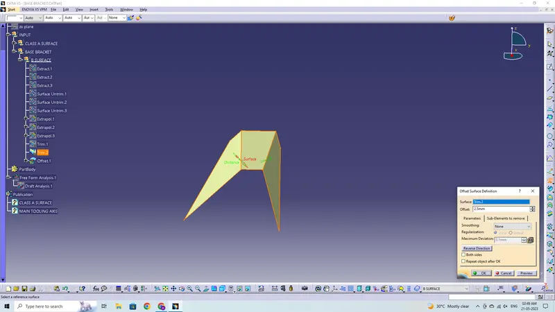
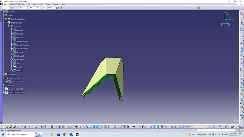
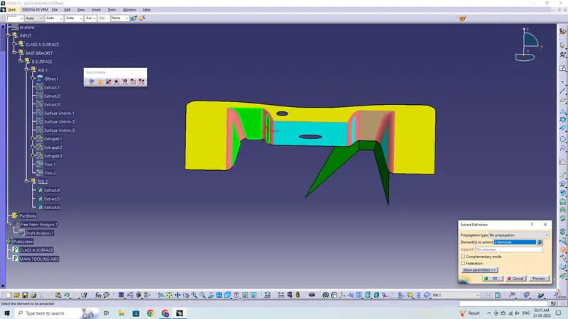
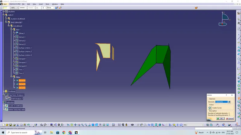
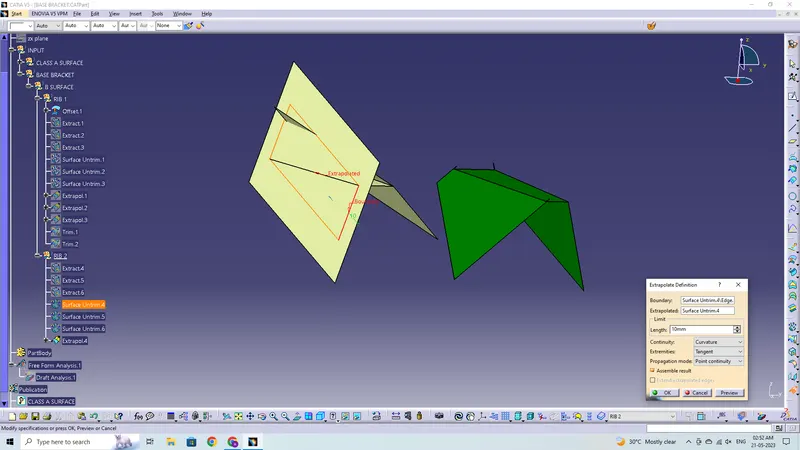
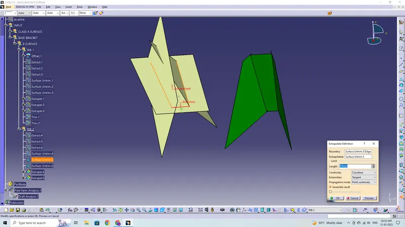
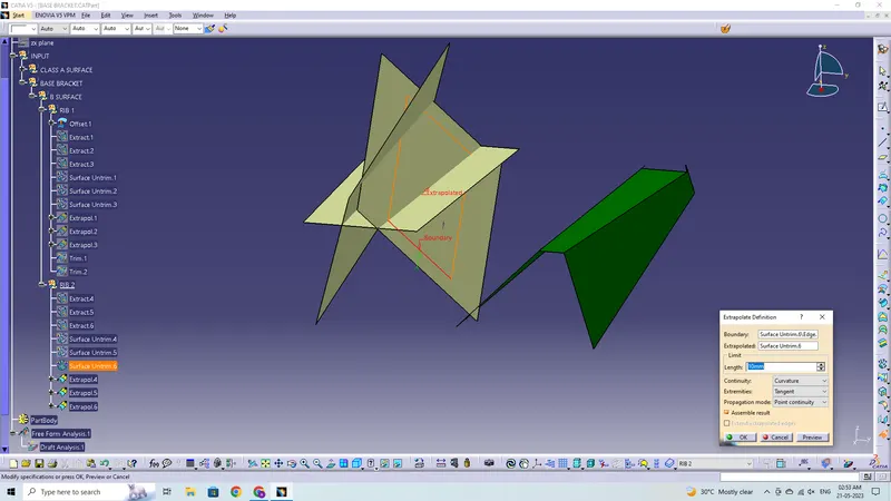
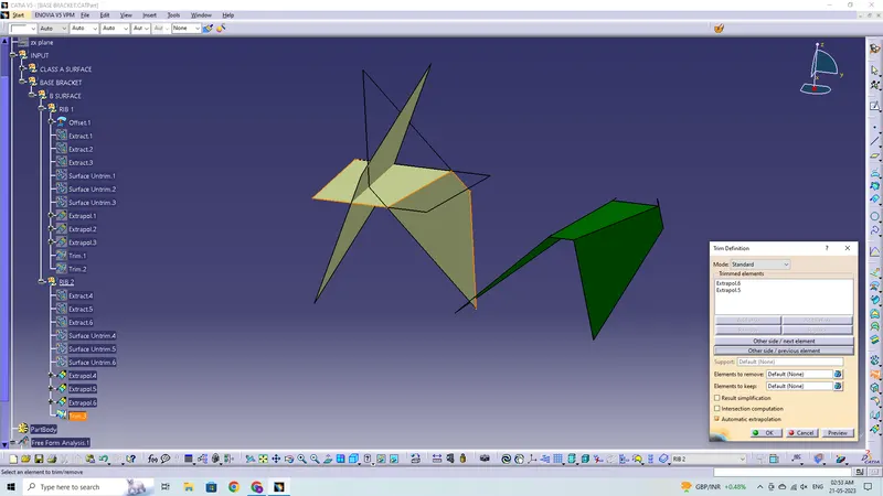
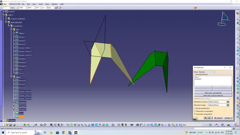
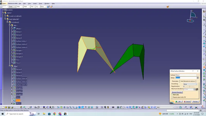
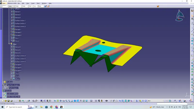
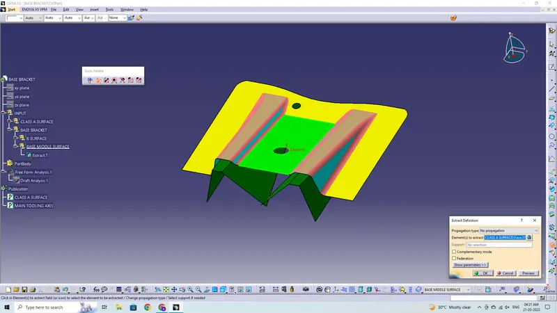
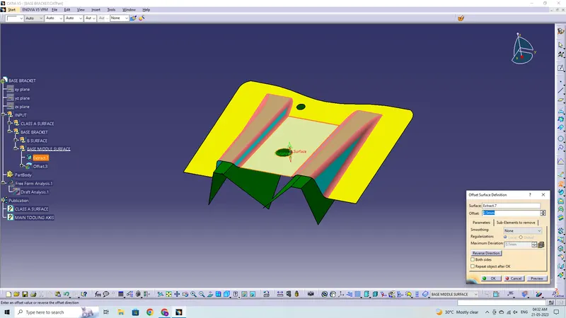
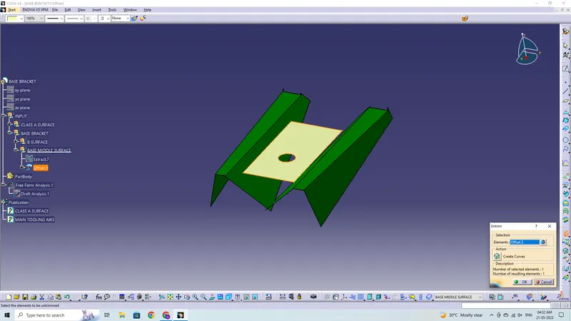
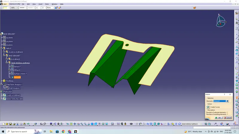
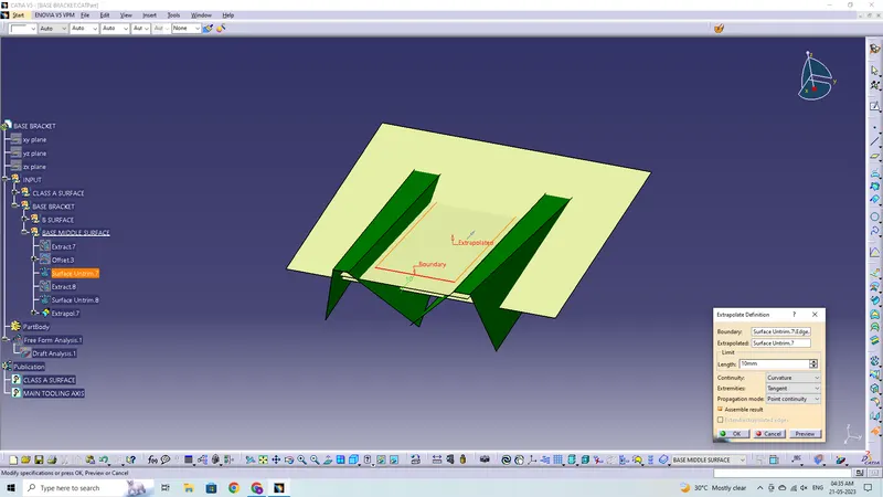
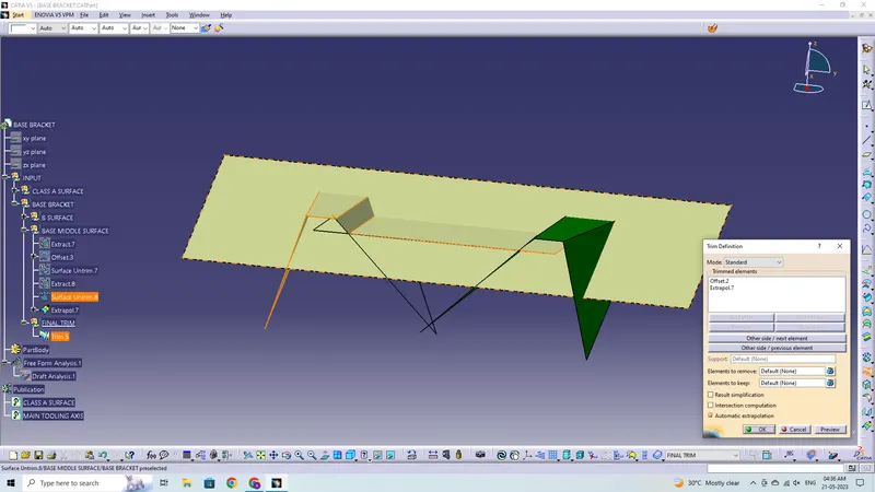
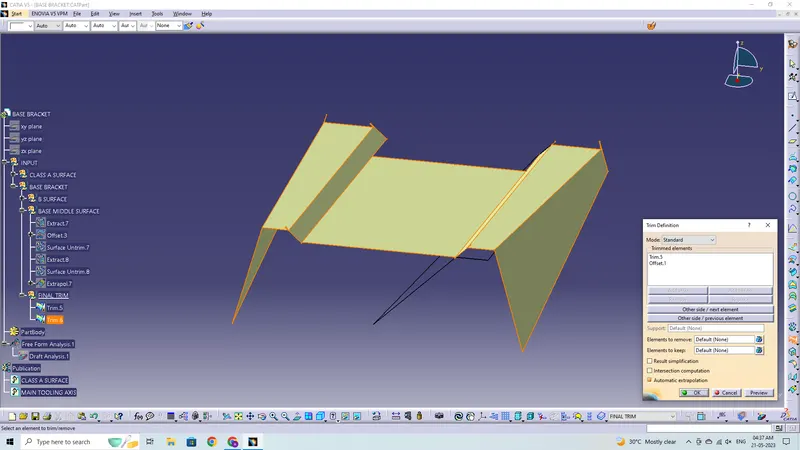
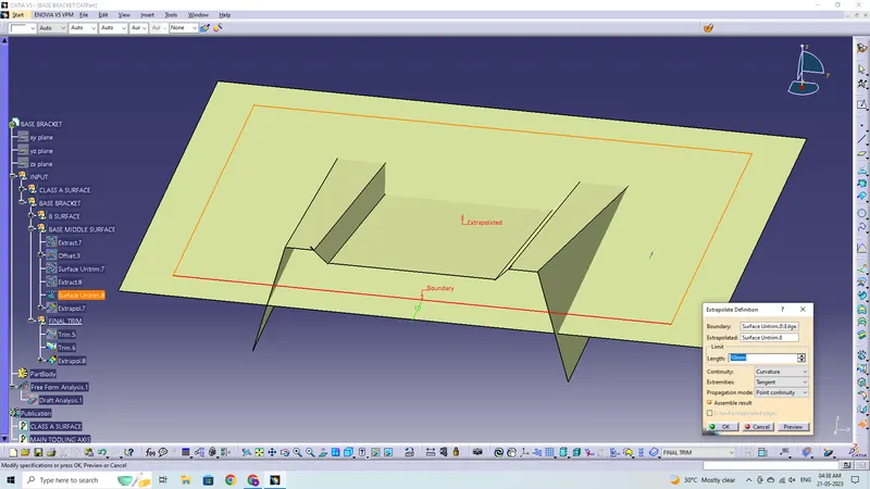
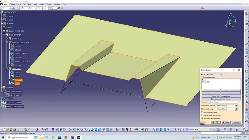
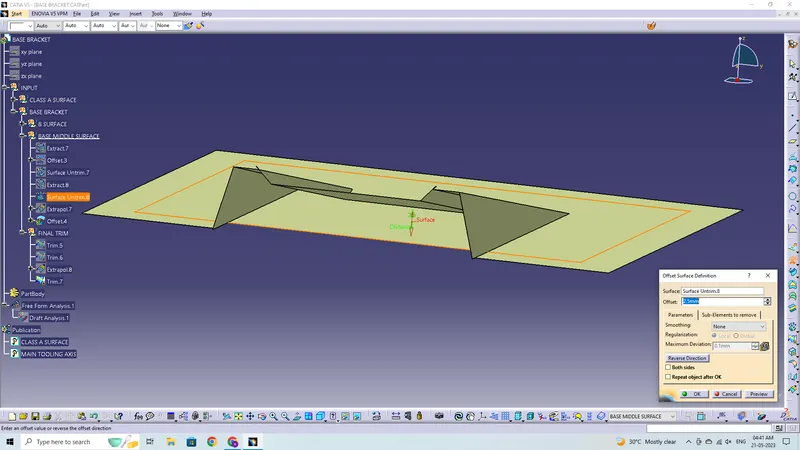
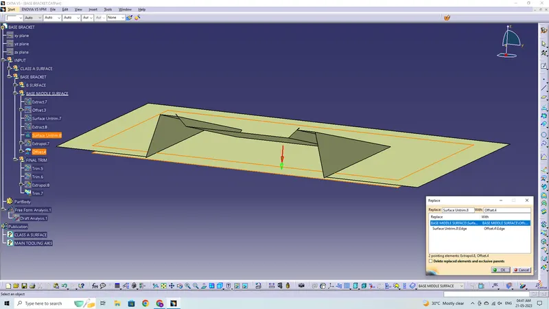
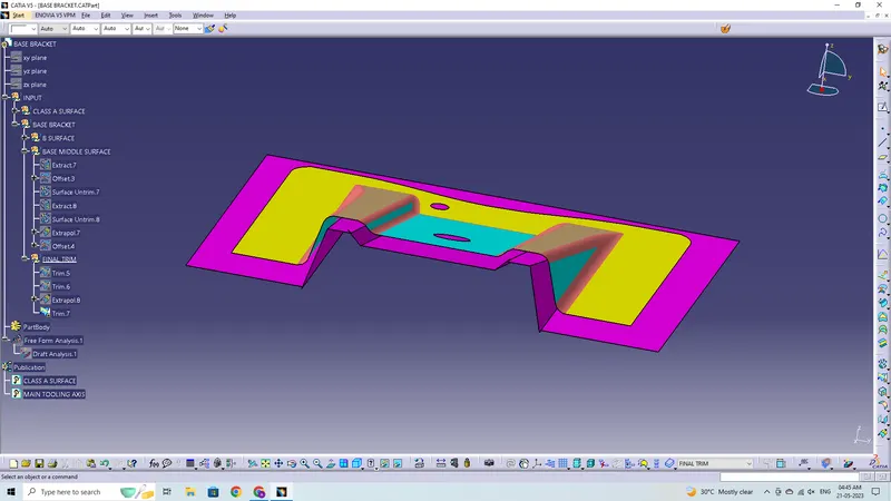
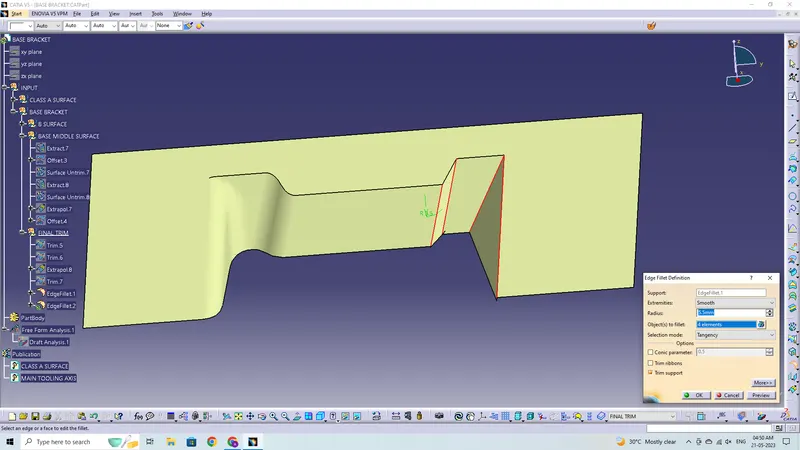
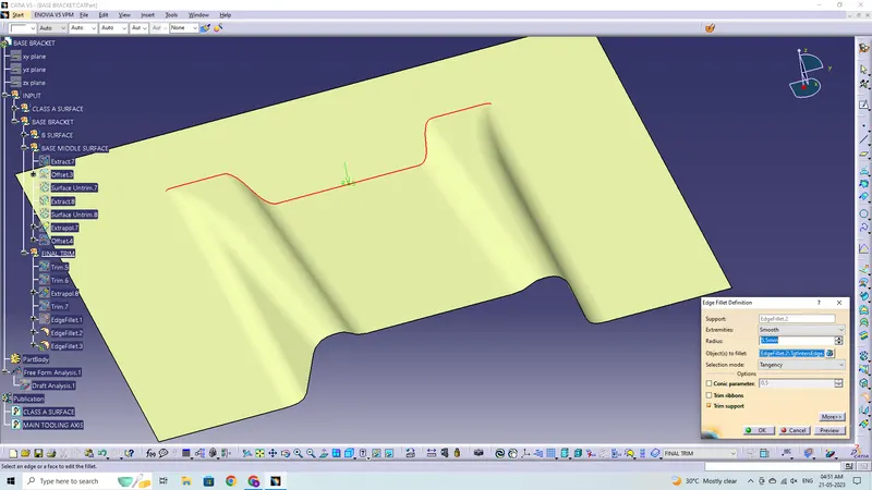
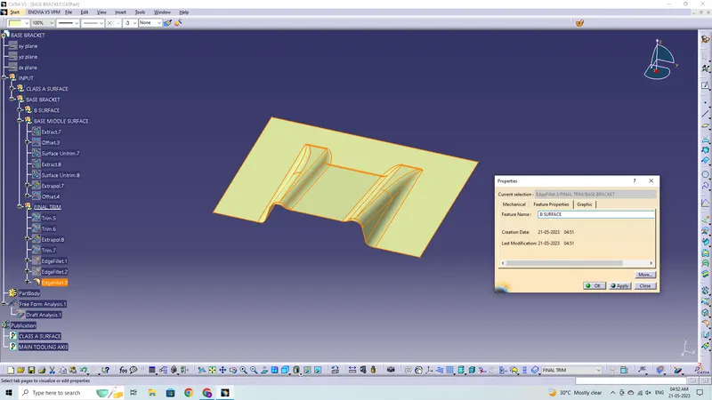
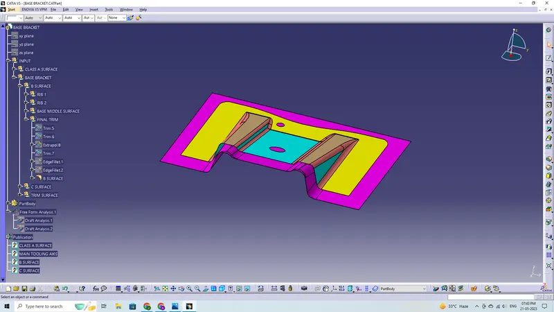
To generate a class-B surface, extract each wall, un-trim it, then extrapolate it to get the shape by trimming the excess surfaces and offsetting it to a particular distance based on the thickness of the model. The B-Surface will serve as the offset surface.
Class-C Surface:
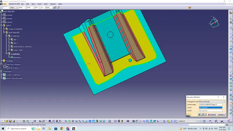
C-Surface is the surface that is produced when the borders of A-surface are swept along the tooling axis to link A to B-surface using the sweep option.
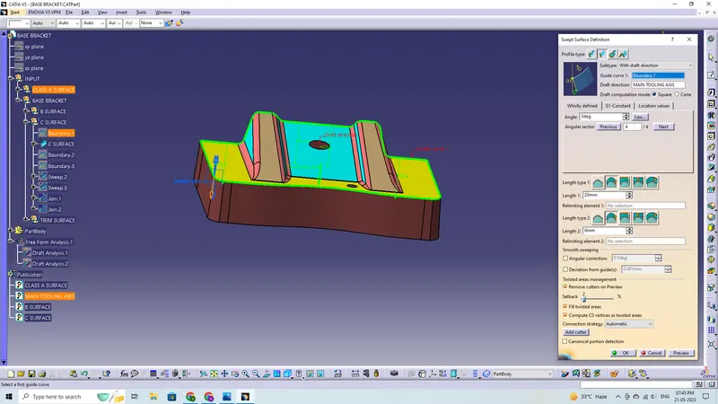
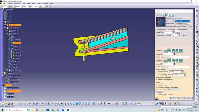
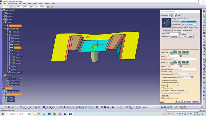
The 'join' command joins all of the swept surfaces together.
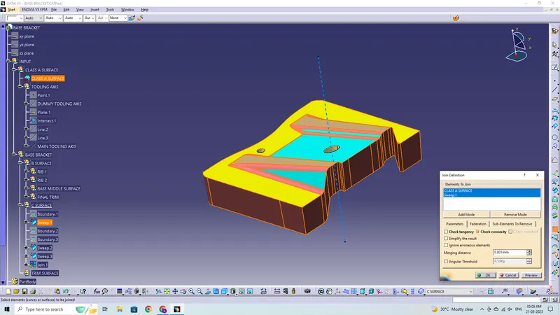
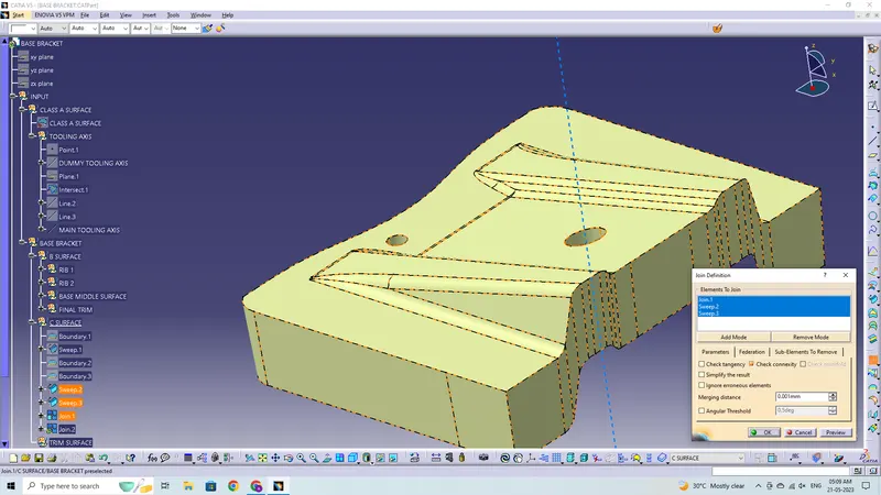
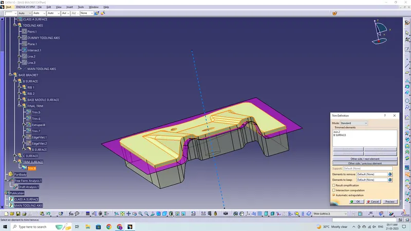
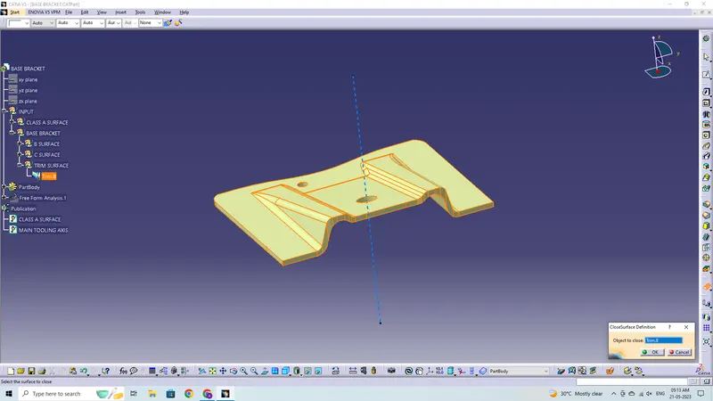
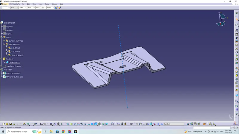
Trimming the extra surfaces from the B and C Surfaces will generate a closed surface, which will then be used to make a solid model using the Closed surface option.
Draft Analysis for Plastic Component:
Tree Structure for the Geometrical Sets
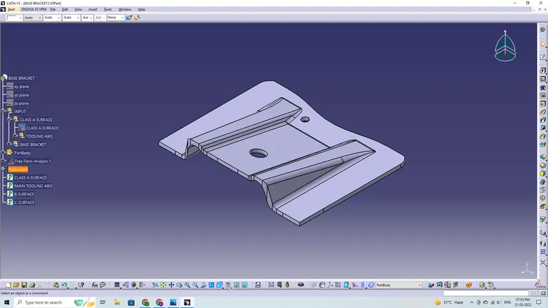
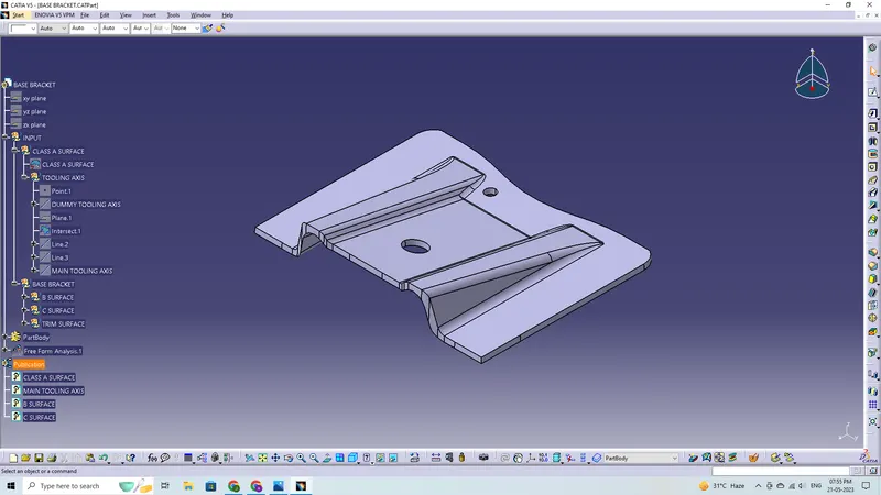

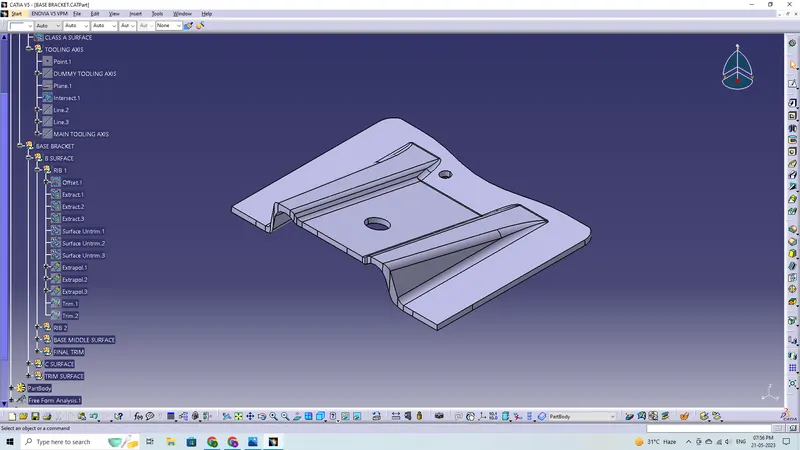
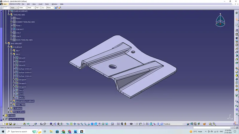
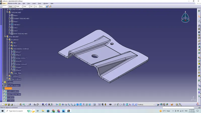
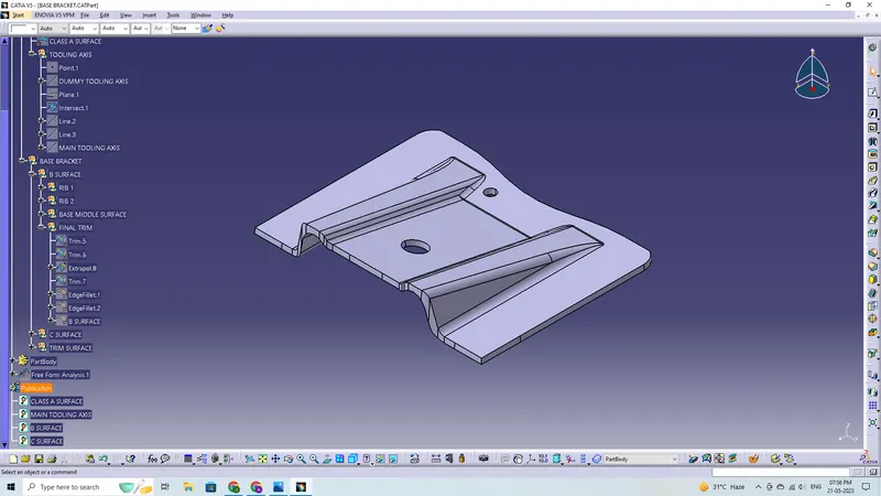
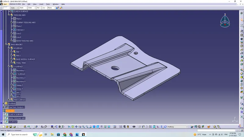
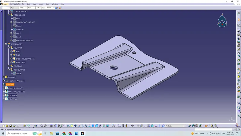
Tree Structure for the Part Body
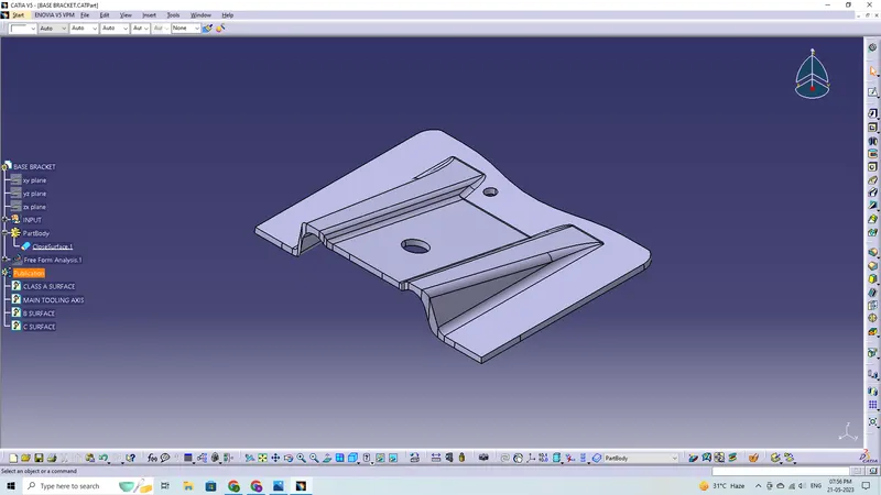
Tree Structure For Draft Analysis
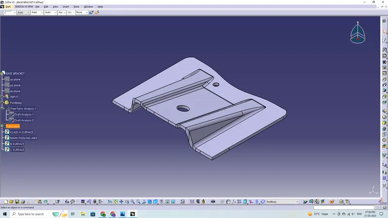
Publication:
Publication is used to easily access and view of the published components
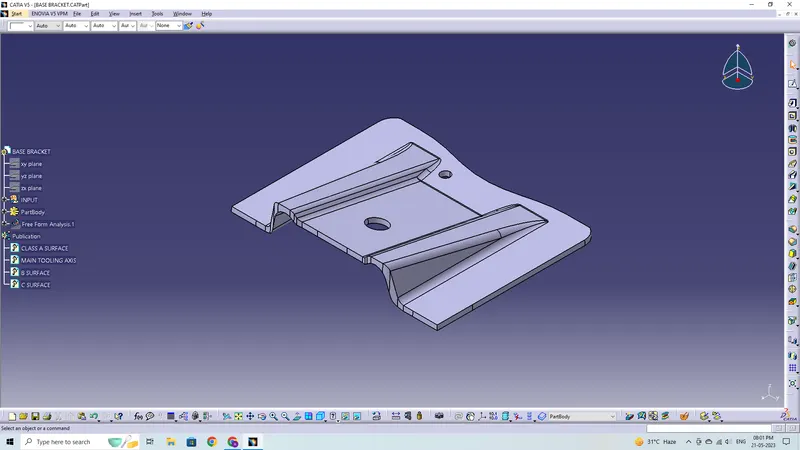
3D Part model in various orientations