Fender Design
Follow the given Master section to create the Drip Area
For the Sill, Bumper, Baffle(Splash), and A-Pillar mount create your own design according to the Engineering standard that you learned.
Prepare a report with all the relevant images included for the mounting points created.
Fender:
The fender in an automobile is an essential component with multifaceted functions. Its primary role involves safeguarding the vehicle's body, wheels, and occupants from a range of external elements and potential hazards encountered in regular driving conditions.
Its primary functions include:
- Protection: The fender shields the wheel and the area around it from road debris, such as rocks, mud, and water, which helps prevent damage to the vehicle's body and other components.
- Aesthetics: Fenders also contribute to the overall appearance and design of a vehicle. Car manufacturers often incorporate the fender design into the car's styling to enhance its visual appeal.
- Safety: In the event of a collision, the fender may absorb some of the impact, helping to protect the vehicle and its occupants. This is particularly true for low-speed impacts and can contribute to minimizing repair costs.
- Regulatory Compliance: Fenders are a regulatory requirement in many places. They help control the spray of water and mud from the tires, improving road safety and visibility for both the driver and other road users.
In case of damage to a fender, it may need to be repaired or replaced. Repairs might involve straightening out dents or scratches, while more severe damage may require the replacement of the entire fender. Fenders can be made of various materials, including steel, aluminum, or composite materials, depending on the vehicle's design and construction.
Wheel Well Area:
The "wheel well area" refers to the space within the vehicle's body structure that surrounds each wheel. It encompasses the region inside the fender and is designed to accommodate the movement of the wheel as well as to protect the vehicle's body from road debris, water, and other external elements. The wheel well area is an integral part of the vehicle's design, contributing to both functionality and aesthetics. It plays a crucial role in housing the wheel and tire assembly, providing support for the suspension system, and often incorporating features to enhance aerodynamics and styling. Additionally, the wheel well area may vary in design among different types of vehicles, such as sedans, trucks, or SUVs, based on their intended use and styling preferences.
Wheel Arch Area:
The "wheel arch area" refers specifically to the arched or curved section of the vehicle's body that surrounds each wheel. It is the visible exterior portion of the wheel well and contributes significantly to the overall aesthetics of the vehicle. The wheel arch area serves both functional and design purposes, providing clearance for the wheel's movement, protecting the vehicle's body from road debris, and influencing the vehicle's exterior styling. Design elements in the wheel arch area can vary widely among different vehicle models and styles. Some vehicles have pronounced and stylized wheel arches that contribute to a more aggressive or dynamic appearance, while others may feature more subtle or integrated arch designs. In addition to its aesthetic role, the wheel arch area also plays a crucial role in accommodating different wheel sizes and types, especially in off-road or performance vehicles.
Types of Fenders:
Full fenders and half fenders serve distinct roles in an automobile, primarily concerning the protection of the vehicle, its components, and external elements. Here's a breakdown of their roles:
-
Full Fender:
- Protection: Full fenders cover the entire wheel well area, extending from the vehicle's body downward to shield the entire wheel and its components. They provide comprehensive protection against road debris, water, and other environmental elements.
- Aerodynamics: Full fenders can contribute to the vehicle's aerodynamics by directing airflow around the wheels and reducing air resistance, which can enhance fuel efficiency.
- Styling: The design of full fenders is often integrated into the overall aesthetic of the vehicle, contributing to its appearance.
-
Half Fender:
- Partial Coverage: Half fenders, as the name suggests, cover only a portion of the wheel well area. They provide some protection to the upper part of the wheel and its components.
- Weight and Visibility: Half fenders are often chosen for specific purposes, such as in certain types of trucks or trailers, where weight reduction and increased visibility of the wheels may be priorities.
- Customization: In some cases, half fenders may be used for aesthetic reasons or customization, giving a distinct look to the vehicle. They may also be preferred in scenarios where quick access to the wheels is necessary.
The choice between full fenders and half fenders depends on factors such as the vehicle's intended use, design preferences, and regulatory requirements. Full fenders are more common in passenger cars, providing comprehensive protection and contributing to the overall design, while half fenders may be seen in commercial vehicles, trailers, or customized applications where specific considerations come into play.
Application of Fender:
The application of fenders in automobiles serves several crucial purposes, contributing to both the functionality and aesthetics of the vehicle. Here are key applications of fenders in automobiles:
-
Protection from Debris:
- Fenders play a vital role in shielding the vehicle from road debris, rocks, mud, and water that can be thrown up by the rotating tires. By covering the wheel well area, fenders help prevent damage to the vehicle's body and protect vulnerable components.
-
Enhancing Safety:
- In the event of a collision or impact, fenders can absorb some of the force, helping to minimize damage to the vehicle and providing an additional layer of safety for occupants.
-
Regulatory Compliance:
- Many regions have regulations that mandate the use of fenders on vehicles. Fenders help control the spray of water and debris from the tires, improving road safety and visibility for both the driver and other road users.
-
Aerodynamics:
- Fenders can contribute to the aerodynamics of the vehicle. Well-designed fenders help manage airflow around the wheels, reducing air resistance and potentially improving fuel efficiency.
-
Styling and Aesthetics:
- Fenders are integral to the overall design and aesthetics of the vehicle. Car manufacturers often use fenders as a stylistic element to create a distinctive look for their models.
-
Wheel and Suspension Support:
- Fenders provide structural support for the suspension system and help secure the wheel and tire assembly in place. This is crucial for maintaining proper alignment and ensuring optimal vehicle performance.
-
Customization:
- In custom or modified vehicles, fenders are sometimes altered or replaced for aesthetic reasons. Different types of fenders, such as full fenders, half fenders, or fender flares, can be chosen to achieve a specific look or accommodate larger tires.
-
Off-Road Applications:
- In off-road vehicles, fenders, especially fender flares, are often used to accommodate larger tires and provide additional clearance. This helps prevent tire rubbing during off-road adventures.
In summary, fenders in automobiles go beyond mere aesthetic considerations and are integral to the vehicle's overall performance, safety, and compliance with regulatory standards. Their design and application may vary based on the type of vehicle and its intended use.
Manfucturing Process:
Metal stamping manufacturing process can quickly and cleanly create solid metal parts and forms. The process uses specialized dies that press sheets of metal into precisely the right form. Auto manufacturers benefit from using metal stamping for parts like fenders and hub caps because the dies can be used again to create consistently sized and shaped parts that meet tight specifications and tolerances. Some key benefits of metal stamping include:
- Cost-Effectiveness: Once the dies have been made, manufacturers can create high-volume runs of automotive parts at a low cost. Metal stamping techniques can handle a variety of metals, which allows companies a large degree of flexibility without additional costs. The metal stamping dies themselves are also cost-effective to create and keep in good working condition. The finishing steps of producing the parts, like plating, are also cost-effective.
- Material Efficiency: Metal stamping processes use sheet metal to create parts. Sheet metal is efficient and doesn’t add wasteful heft or thickness to the part. Sheet metal can be used for an array of parts, including structural elements, the chassis, and mechanical components in the engine or transmission systems.
- Automation: Metal stamping processes can be handled entirely by machinery. Not only does this reduce the risk of human error or inconsistency, but it also lowers labor costs and keeps employees safe.
Types of metal stamping process:
There are three popular types of metal stamping presses used for automotive and other industrial parts. They include:
- Mechanical Presses: which have a mechanical flywheel powered by a motor.
- Hydraulic Presses: which have pressurized fluids that control the pressure and application of force on a workpiece.
- Mechanical Servo Presses: which use only motors and no mechanical flywheels.
- Structural Intergrity: The Drip Area Mounting plays a crucial role in maintaining the overall rigidity and strength of both the fender and adjacent body panels.
- Aesthetic Integration: Properly designed Drip Area Mountings contribute to seamless integration between different body parts, enhancing visual appeal by creating smooth lines and contours.
2. Sill Mounting: The Sill Mounting involves attaching or integrating the lower section of the fender with other components like rocker panels or side skirts. It provides additional reinforcement, stability, and protection for this vulnerable area against impacts from road debris or curbs.
Importance:
- Impact Resistance: The Sill Mounting helps absorb or distribute energy during minor collisions or contact with objects at ground level, minimizing damage to both the fender and surrounding areas.
- Improved Aerodynamics: A well-designed Sill Mounting contributes to reducing drag by ensuring smooth airflow around wheel wells, improving vehicle efficiency.
- Structural Support: Bumper mountings reinforce connection points between bumpers and fenders, to sustainability & integrity during minor impacts.
- Crash Energy Management: In case of an accident, the bumper mounting system aids in absorbing and dissipating impact energy to protect both the fender and occupants.
- Structural Intergrity: The A-Pillar Mounting ensures that forces acting on the fender are correctly distributed through its connection with the rigid A-pillar structure.
- Crashworthiness: Properly designed mountings contribute to maintaining occupant safety during frontal collisions by effectively transferring impact loads away from critical areas.
- Aerodynamic Efficiency: By properly securing baffles within the fender assembly using robust mountings, it helps optimize airflow patterns around wheels, reducing drag & enhancing overall vehicle aerodynamics.
- Noise Reduction: Effective baffle mounting reduces unwanted noise caused by turbulent airflow inside wheel wells, resulting in improved ride comfort&acoustic performance.
Fender Mounting Areas:
There are majorly five mounting areas in fender which is named in below:
- Drip Mounting Area
- Bumper Mounting Area
- Sill Mounting Area
- A-Pillar Mounting Area
- Baffle/Splash Mounting Area
Procedure:
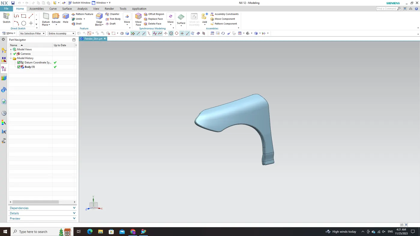
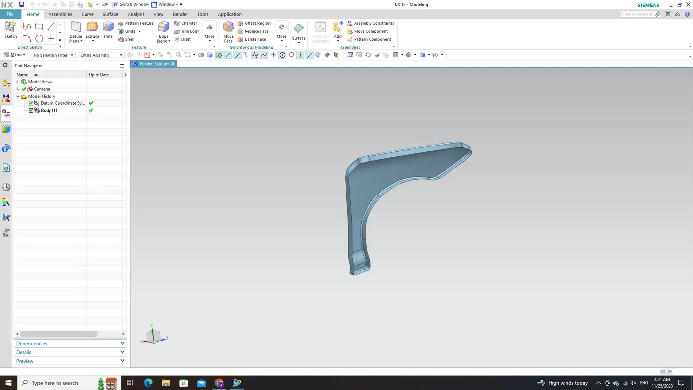
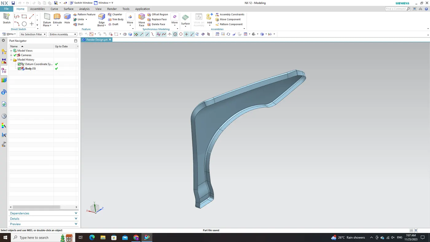

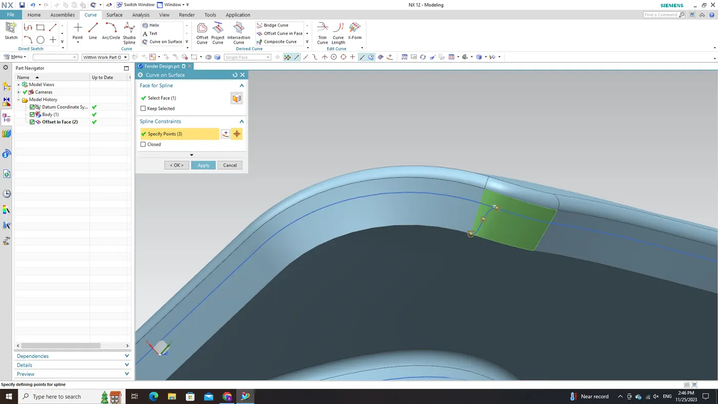
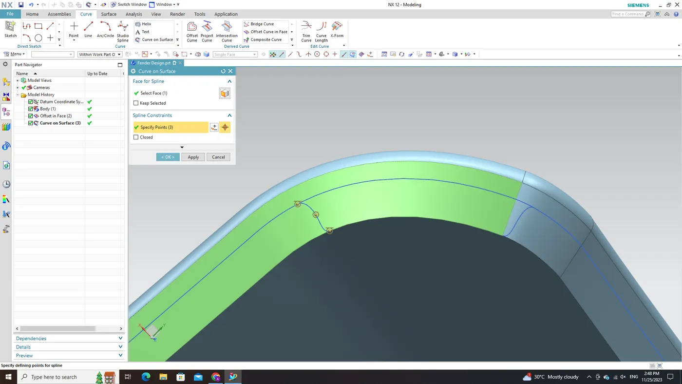
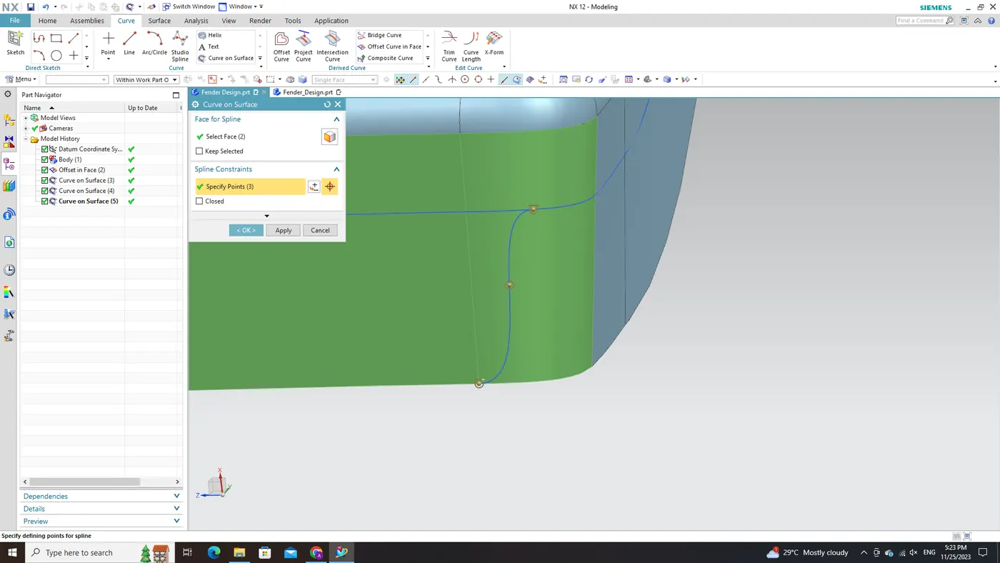
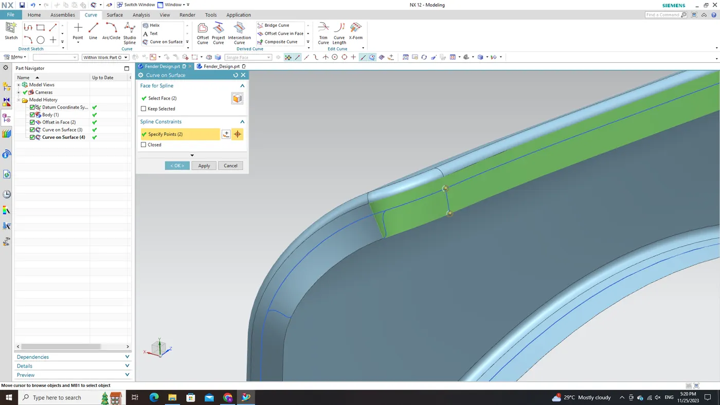
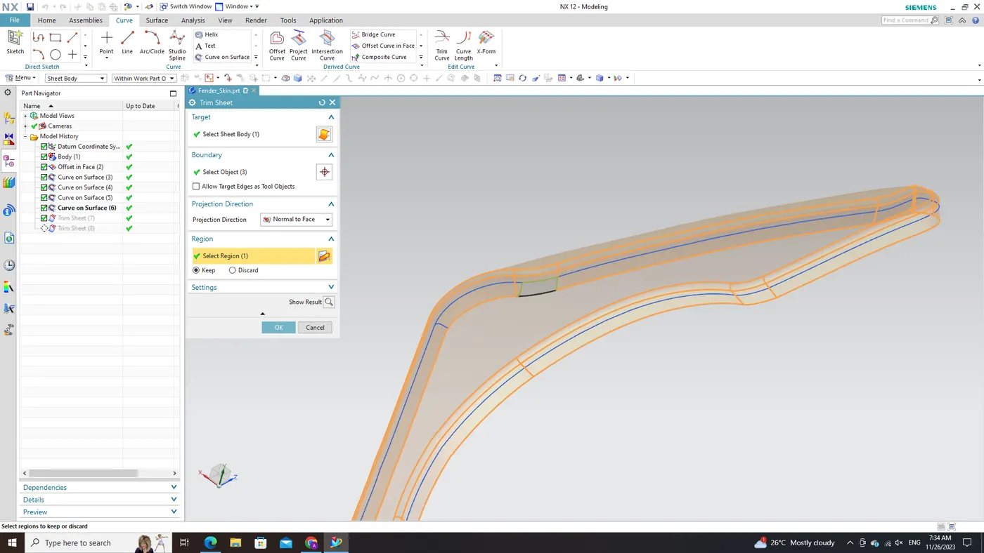
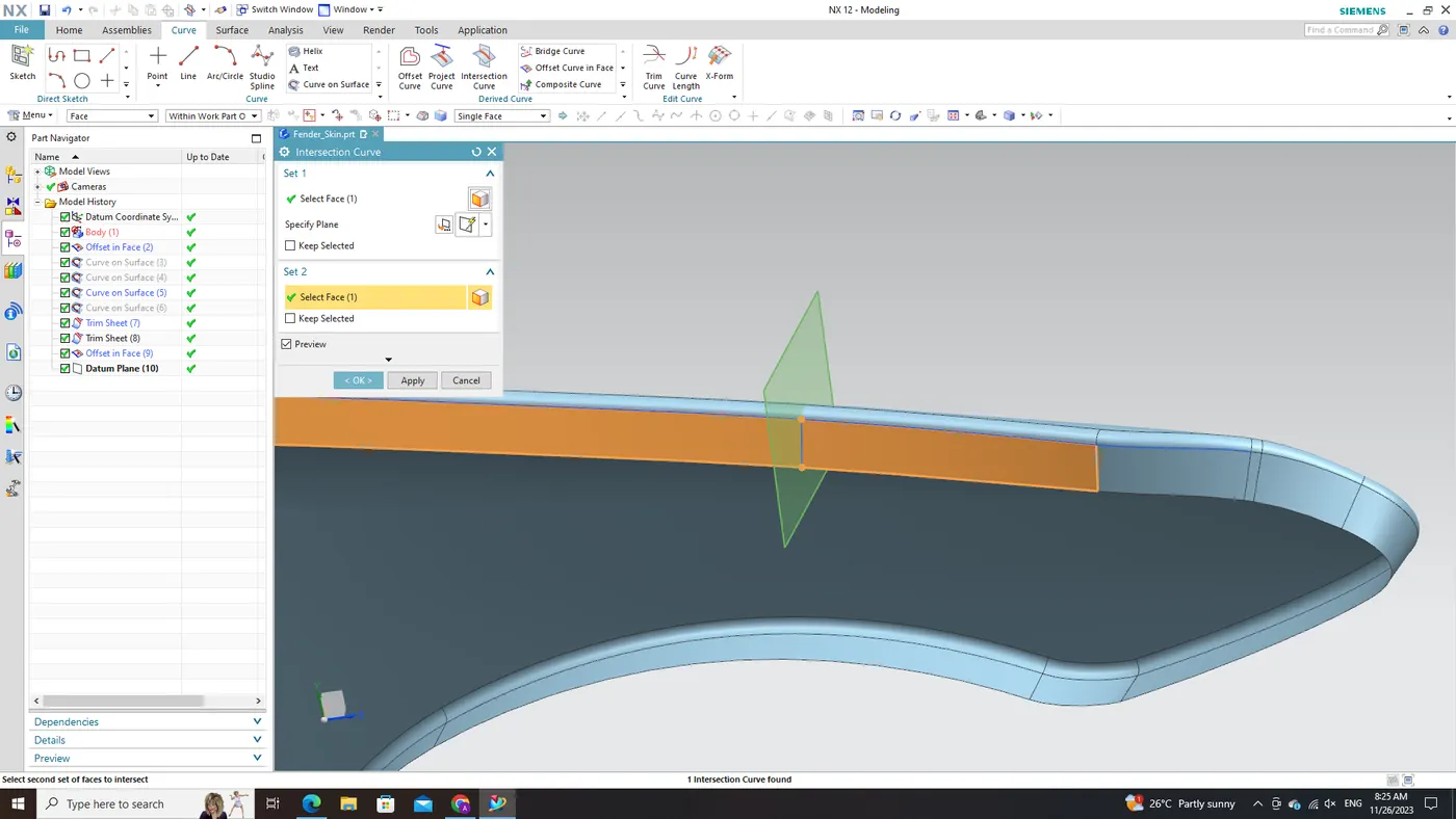
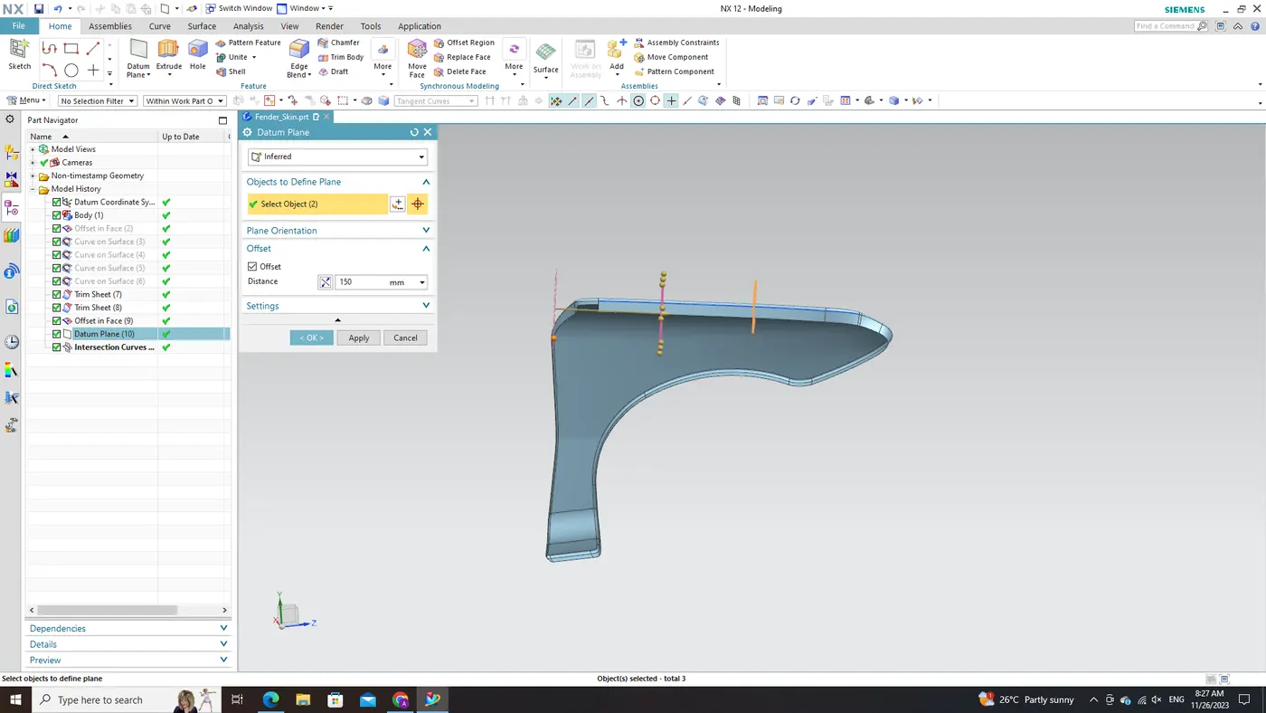
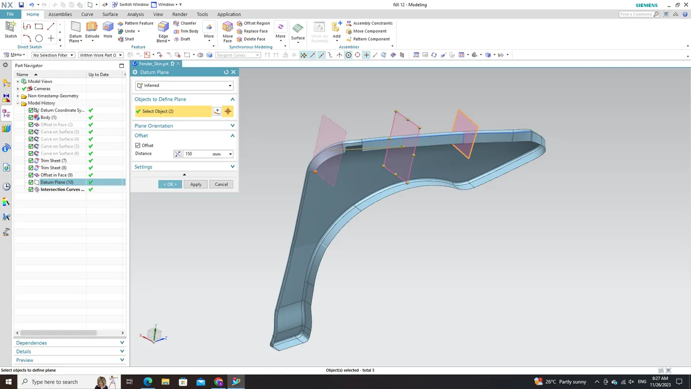
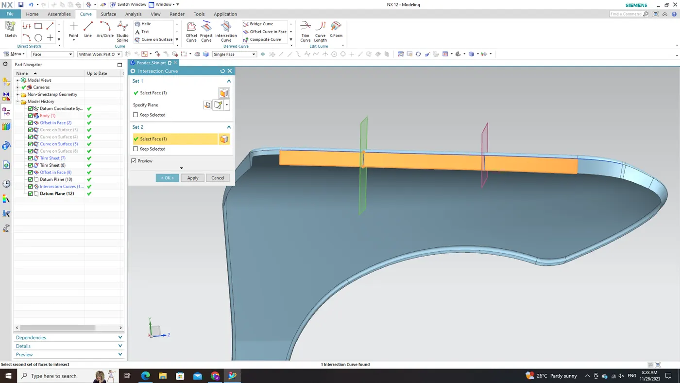
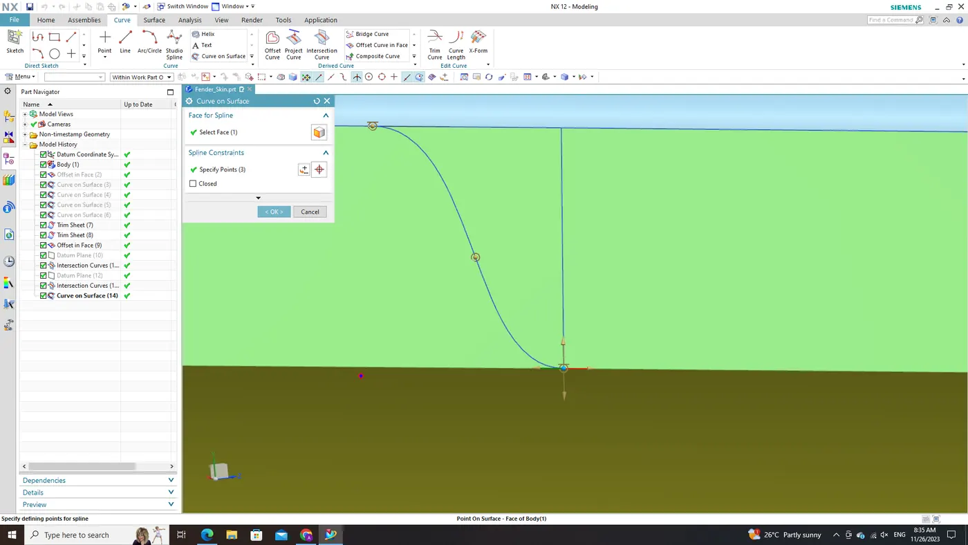
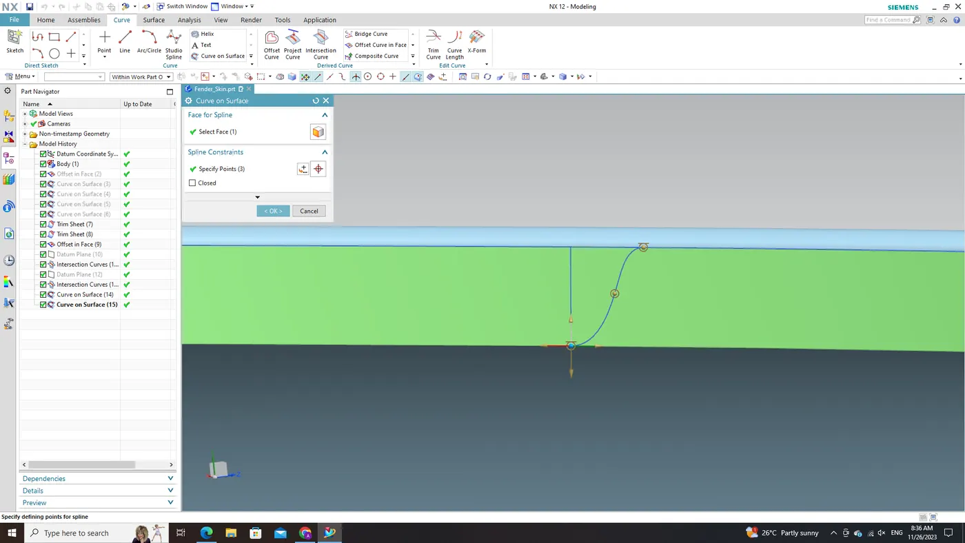
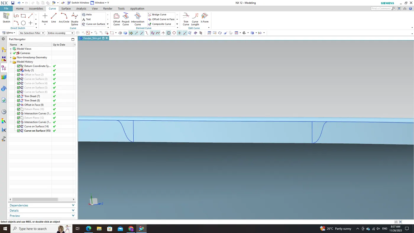
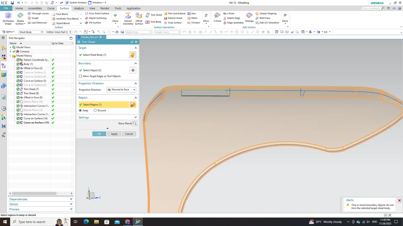
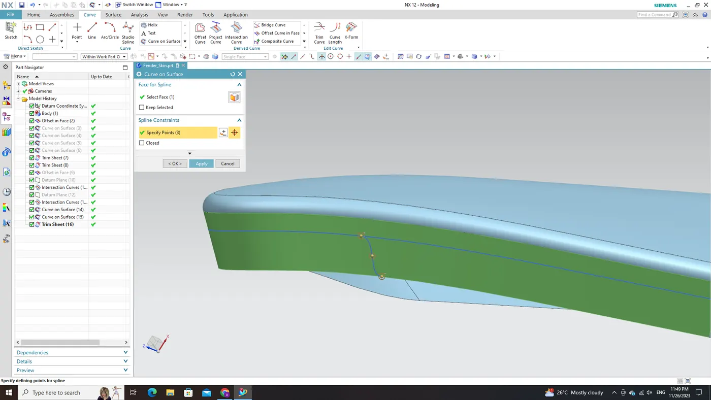
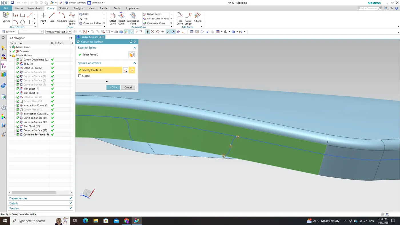
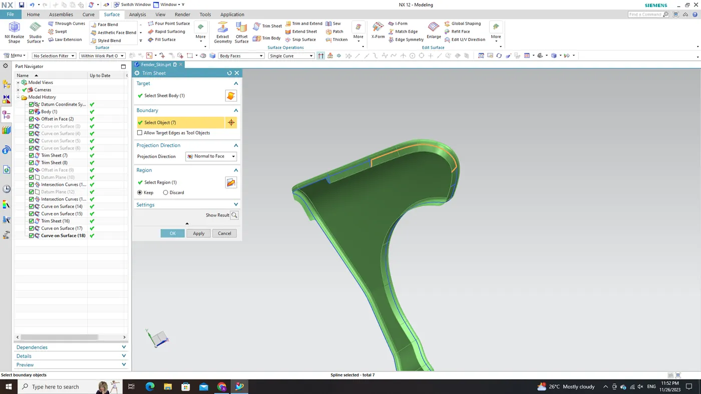
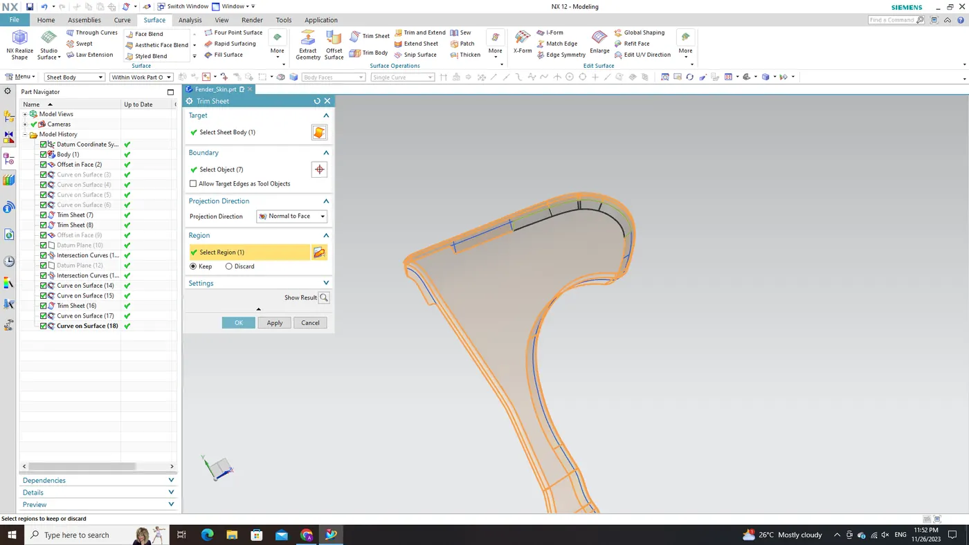
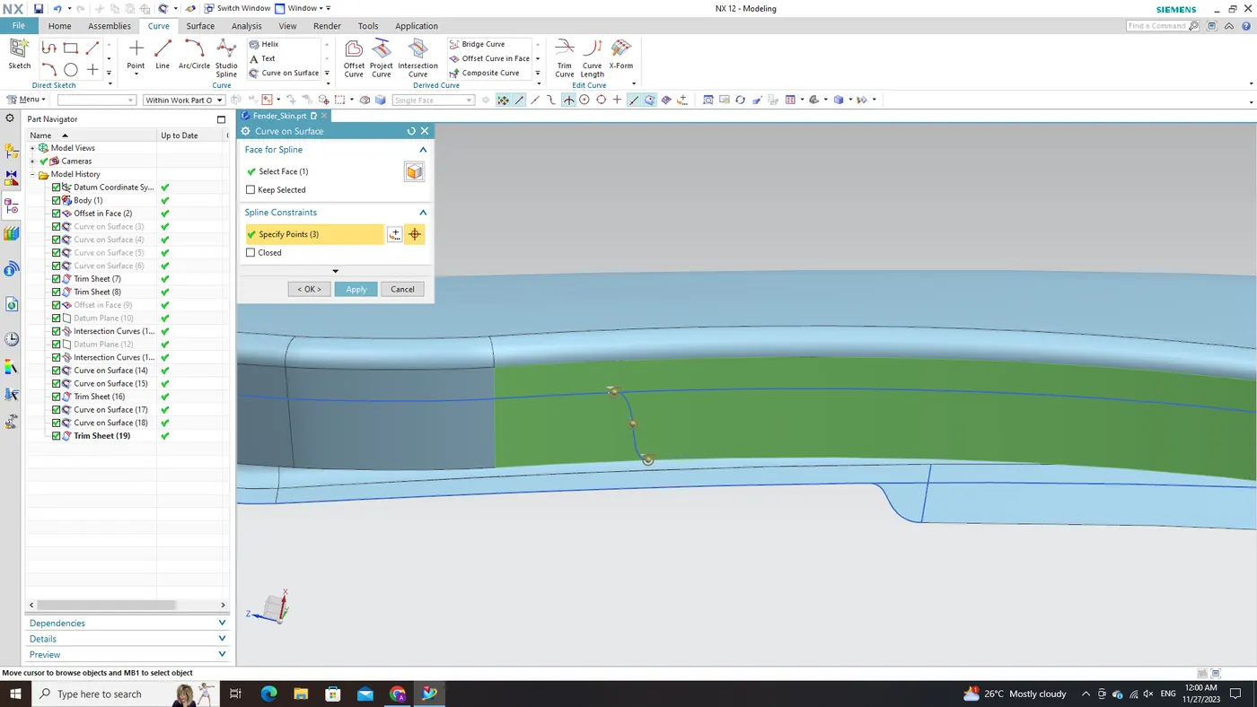
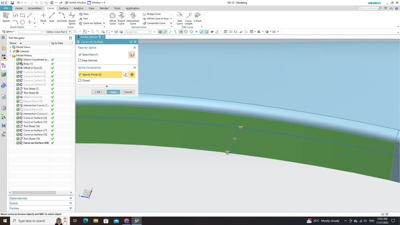
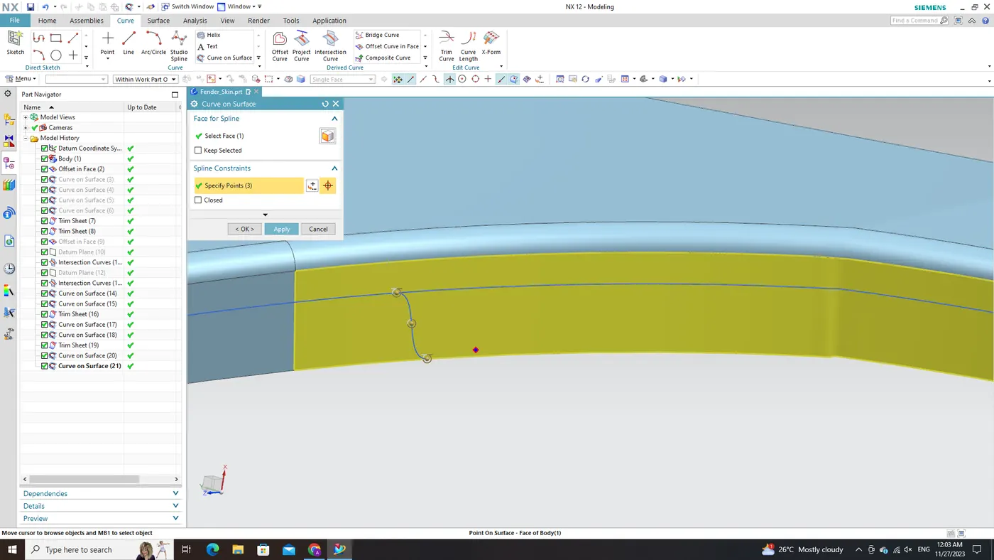
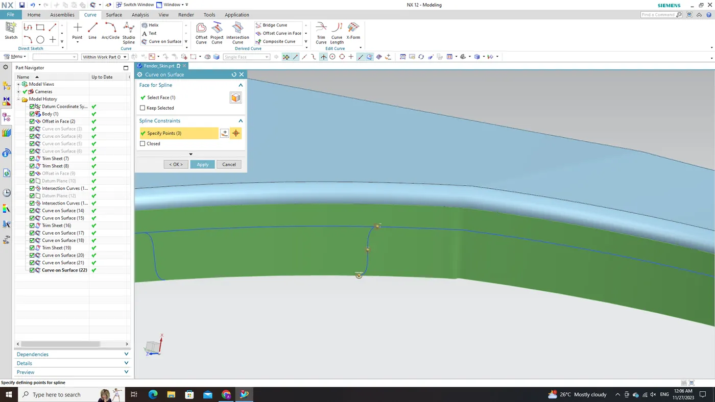
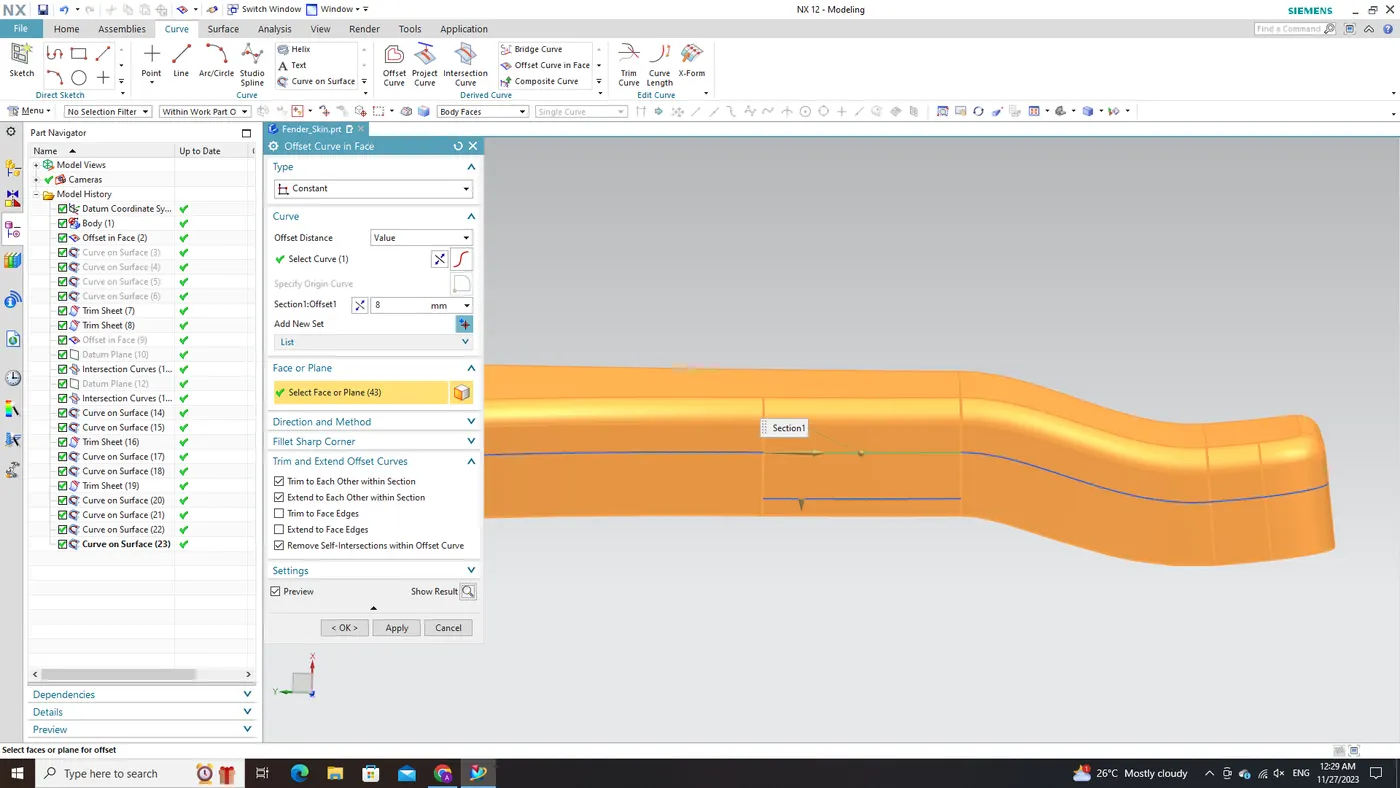
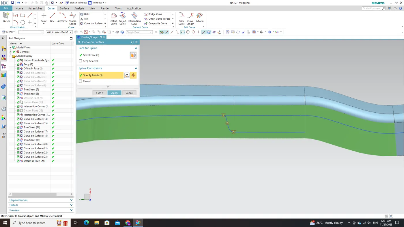
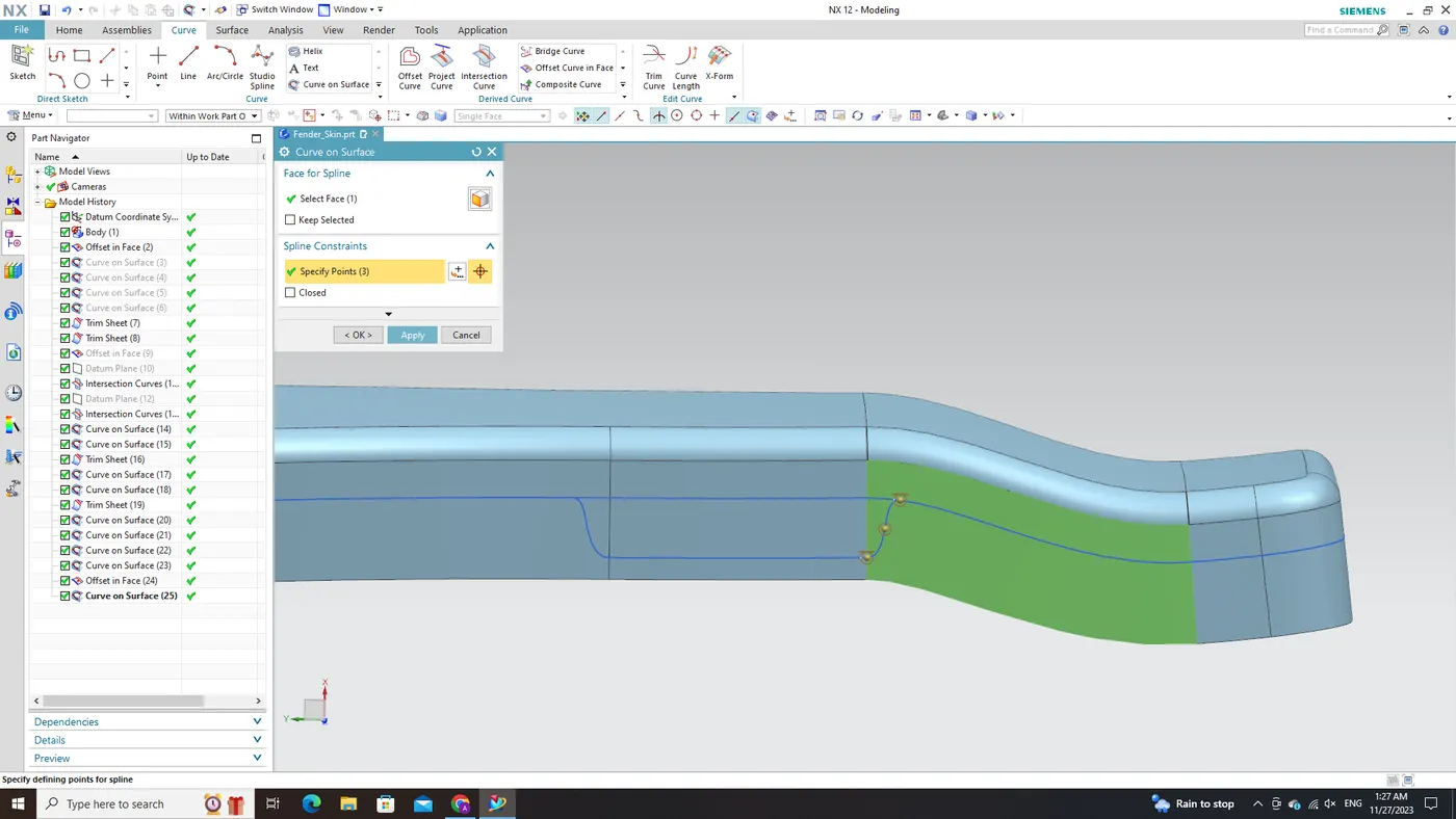
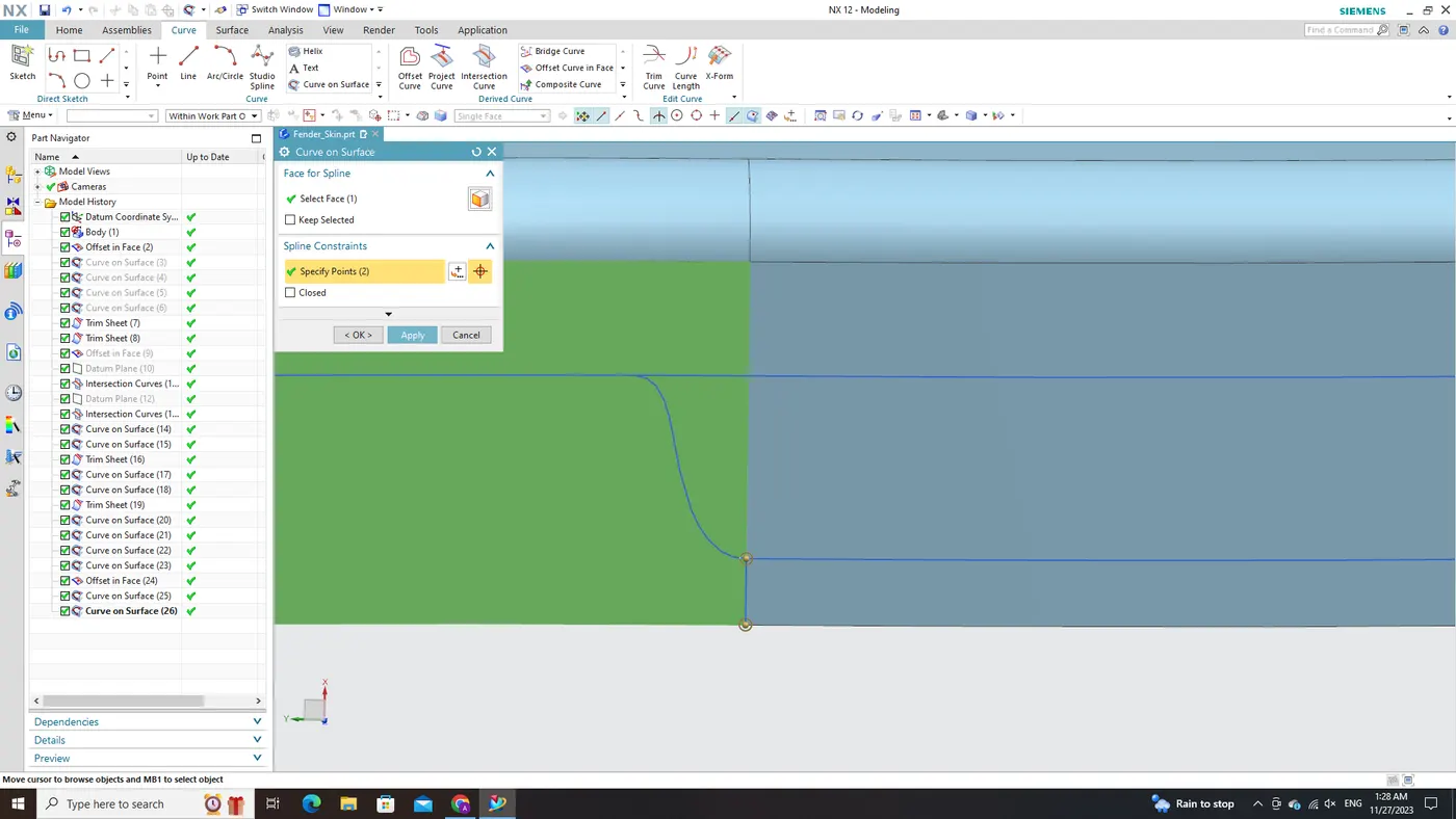
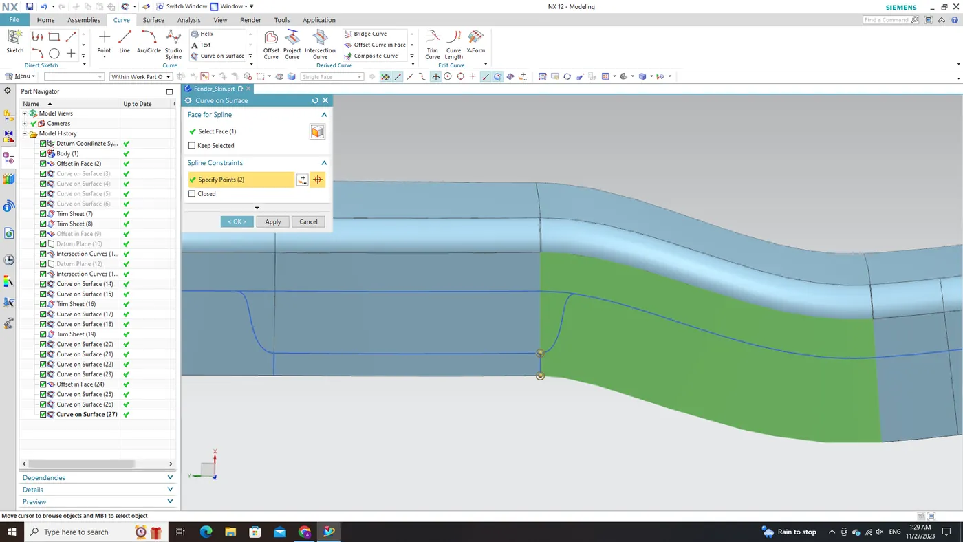
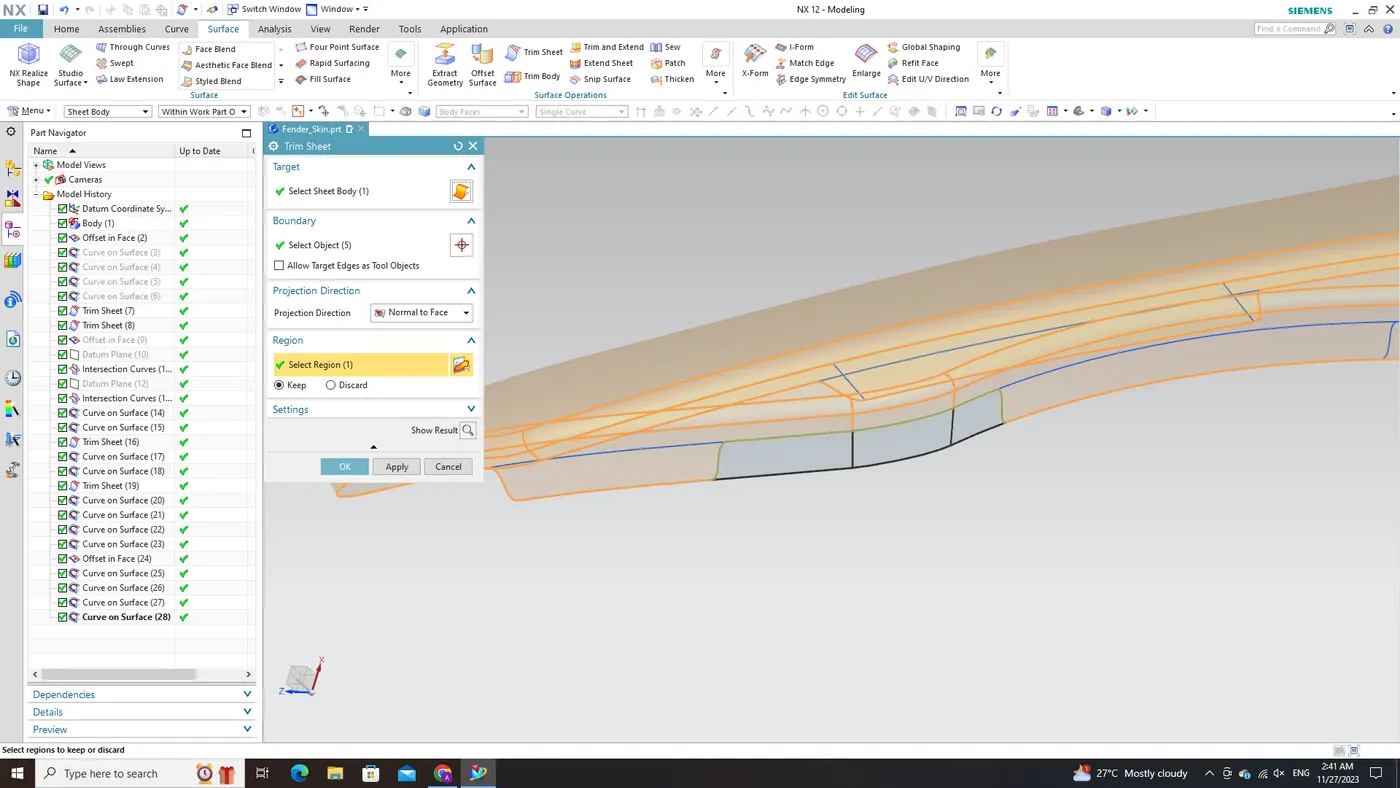
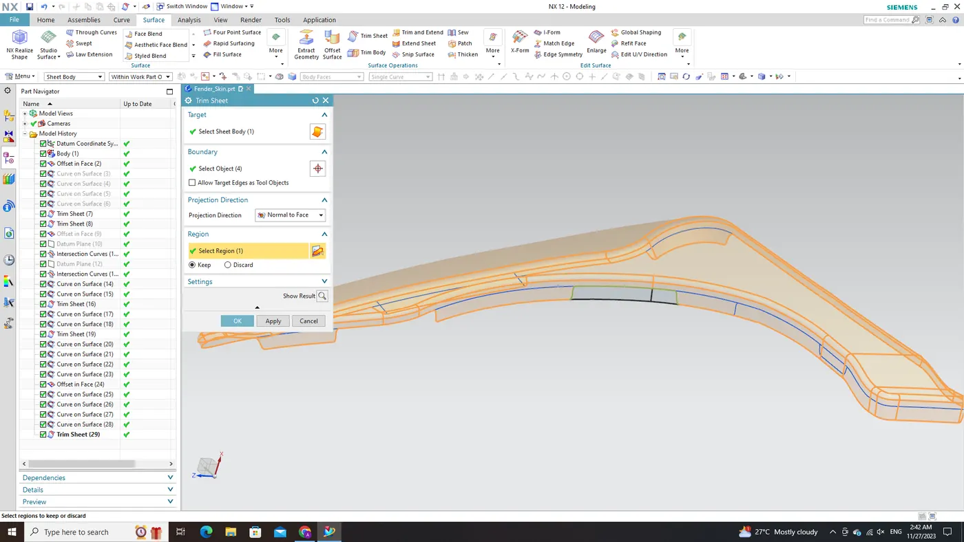
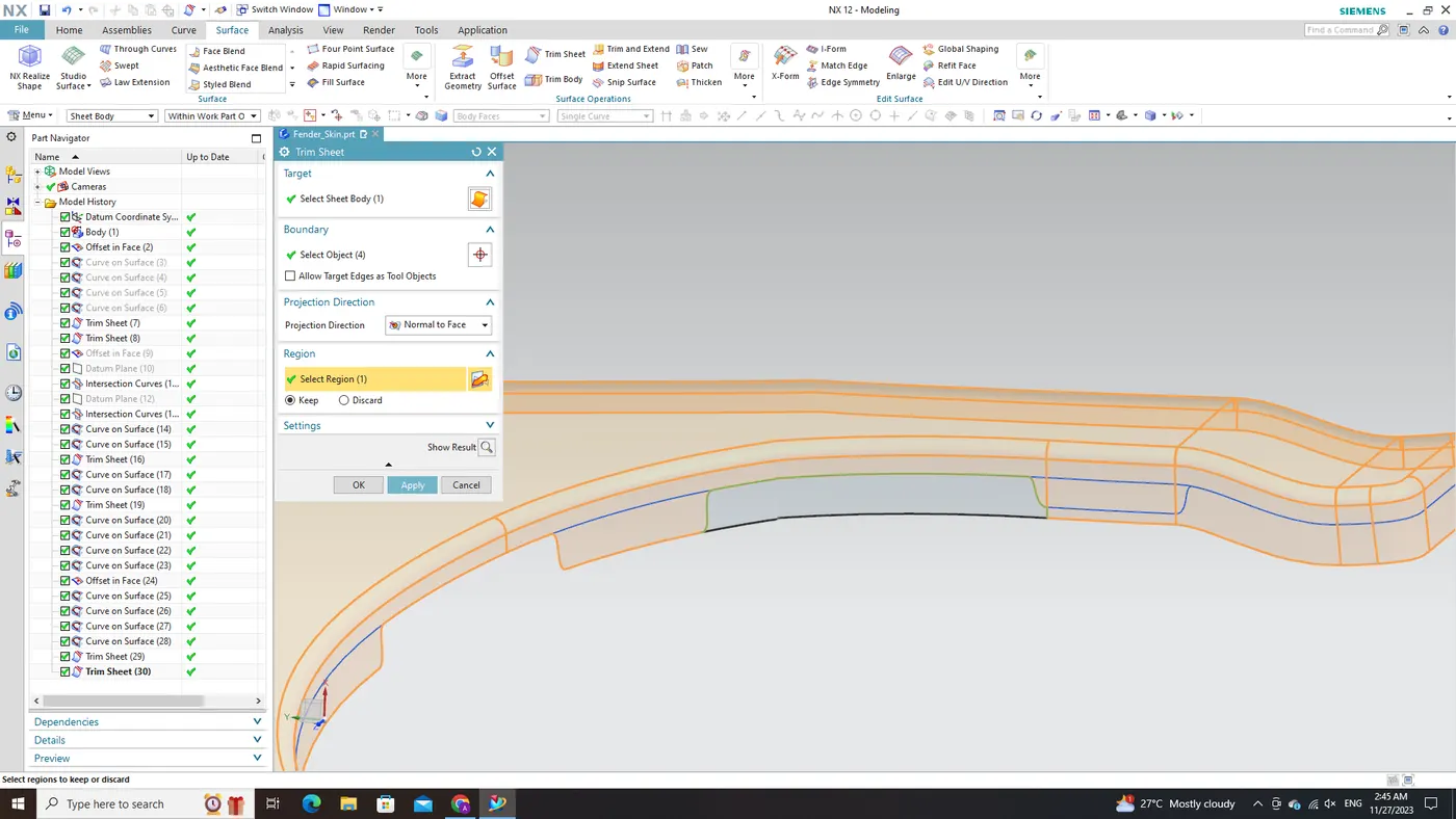
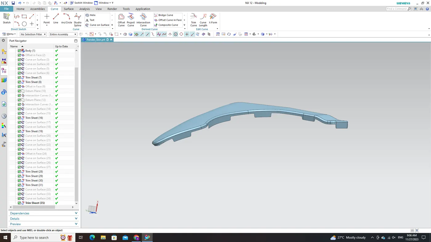
A- Pillar Mounting Area:
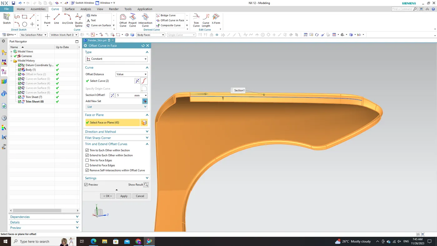
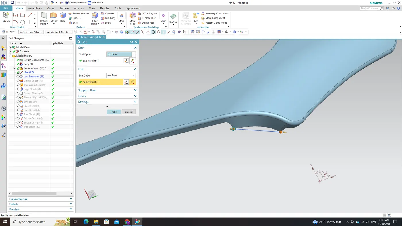
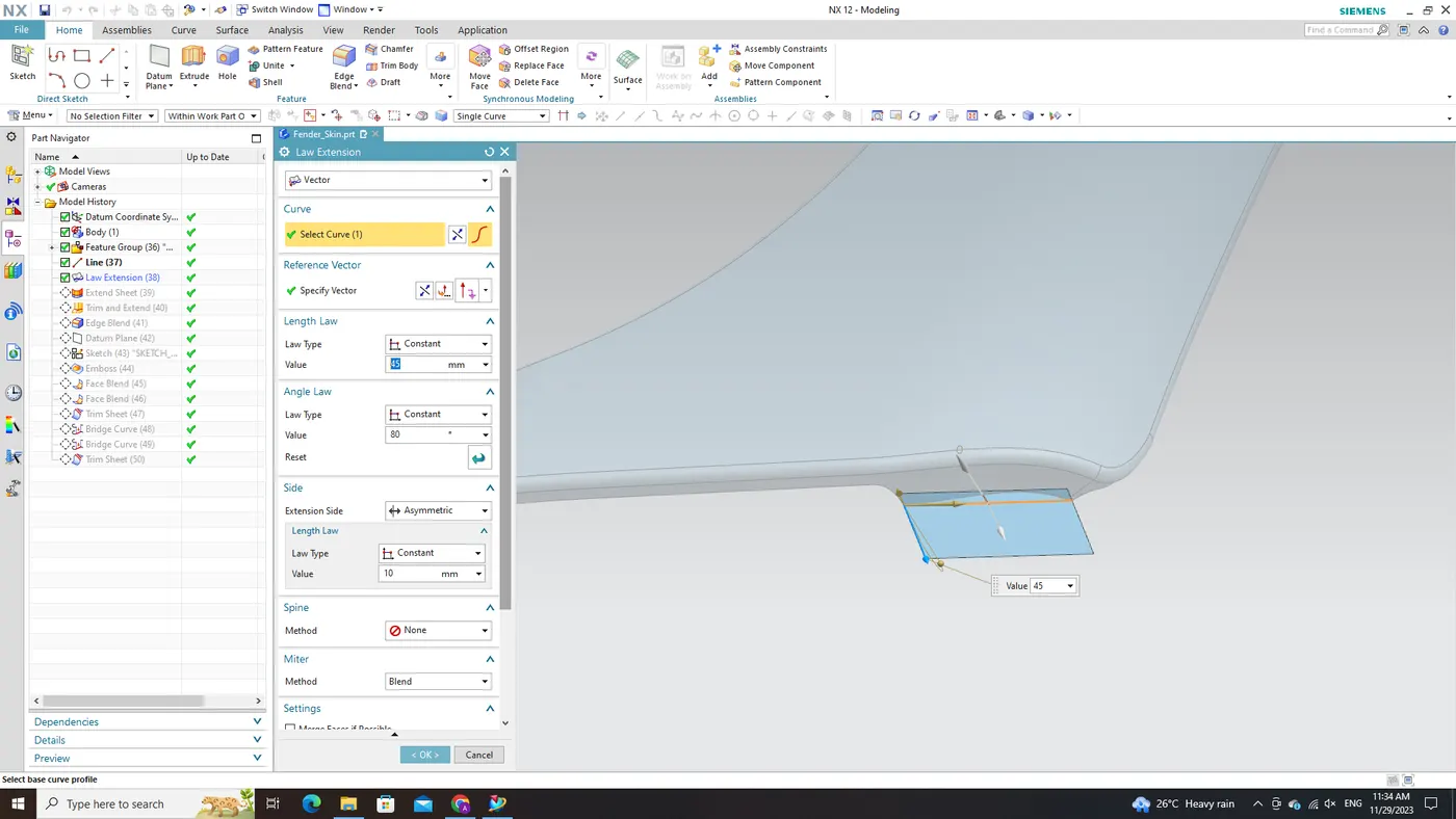
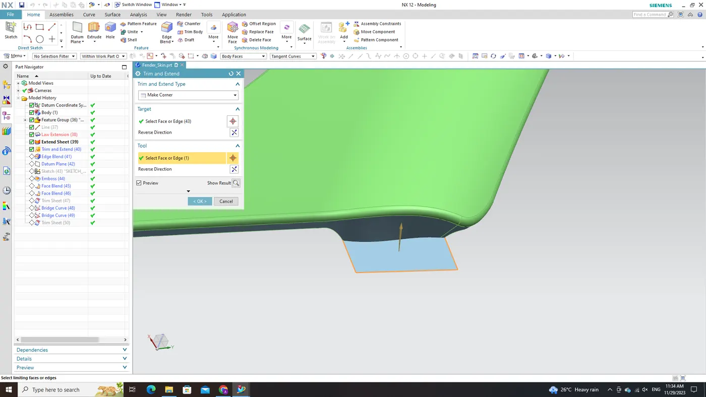
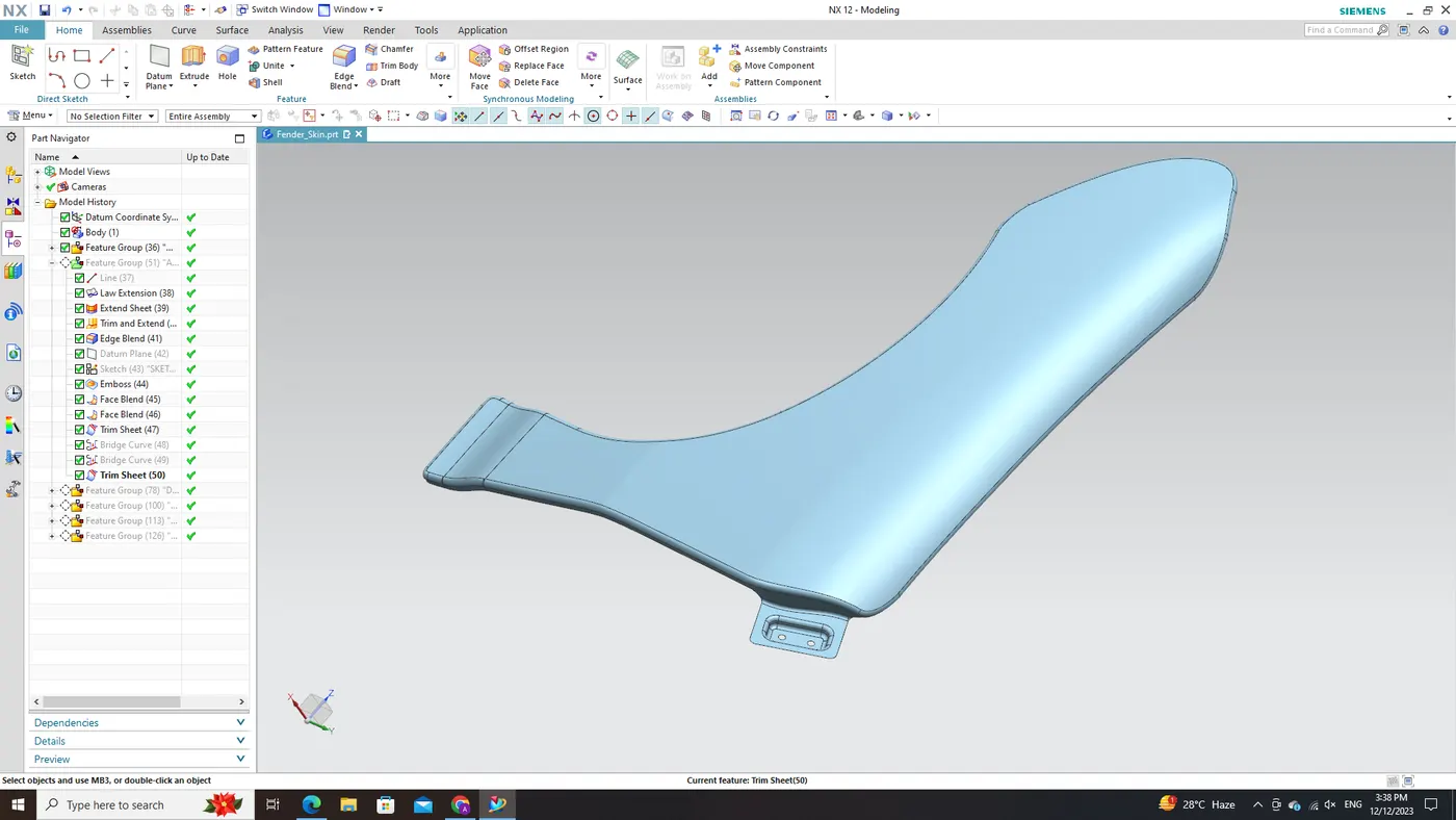
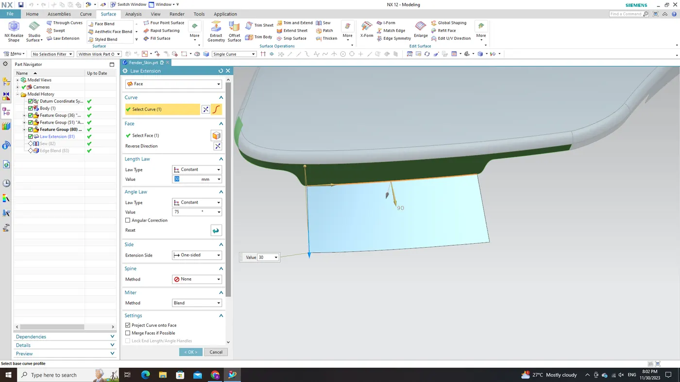
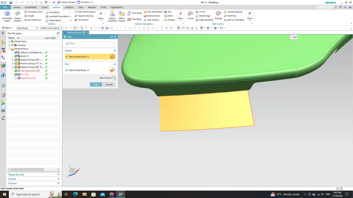
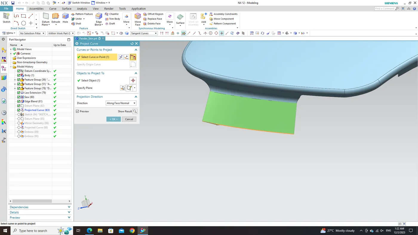
To generate the embossed region and hole, we initiate the process by choosing the endpoints of the previously established mount. A 3D line is then formed using these identified points, serving as a foundational reference for our design objectives. The utilization of NX CAD's robust "Law Extension Command" becomes crucial at this stage. This command empowers us to generate a new surface that lays the groundwork for the desired features. By extending surfaces based on specified laws or mathematical equations, the result is a faithful representation of our design intentions.
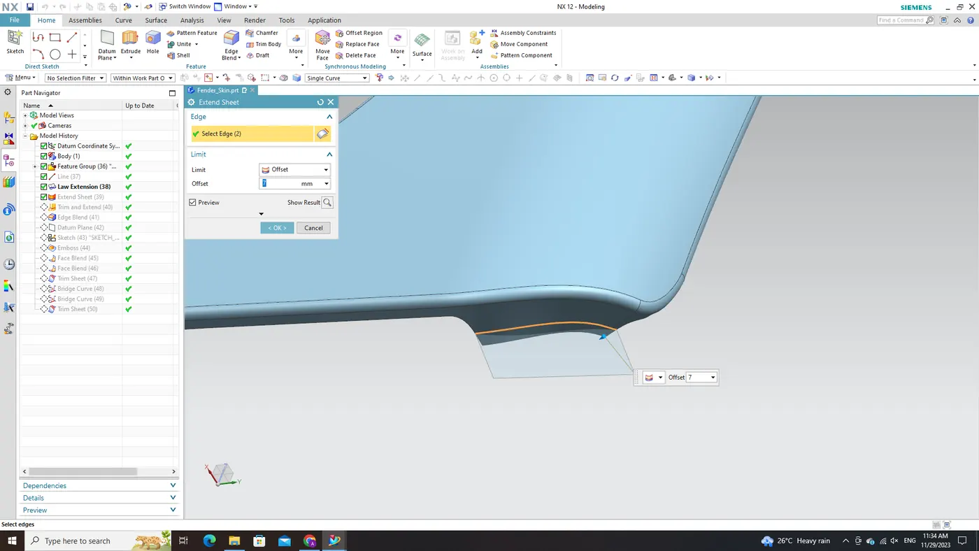
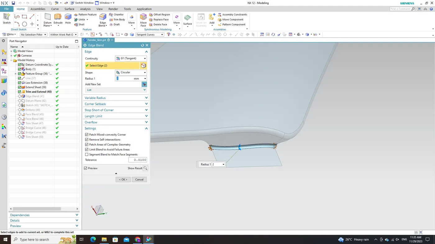
In this specific instance, the 'Extend Sheet' command within NX CAD is employed to elongate the lower edge of the mount. This particular command is adept at extending sheet-like surfaces while preserving their original form and continuity. The concluding step involves the application of the 'Trim & Extend' command in the NX CAD software. This operation entails trimming and extending the two surfaces in unison, aligning them precisely according to our specifications. This meticulous process ensures a seamless integration and alignment between diverse components of our design. By meticulously following these steps—selection of endpoints, creation of a 3D line, utilization of the 'Law Extension Command,' extension of sheet edges with 'Extend Sheet,' and execution of trim and extension operations—we attain a well-defined embossed region and hole within the fender mounting surface. These systematic procedures guarantee a smooth integration with adjacent components while adhering to exacting design specifications.
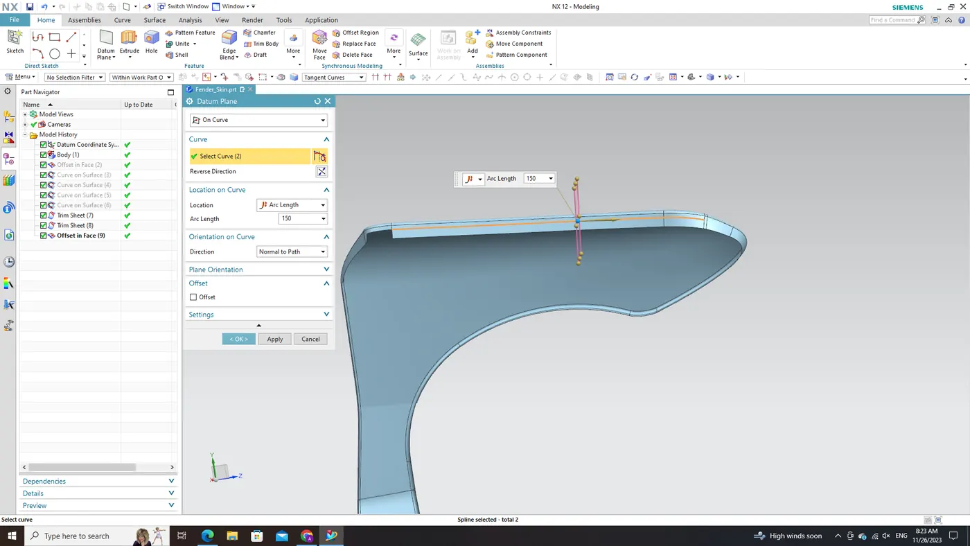
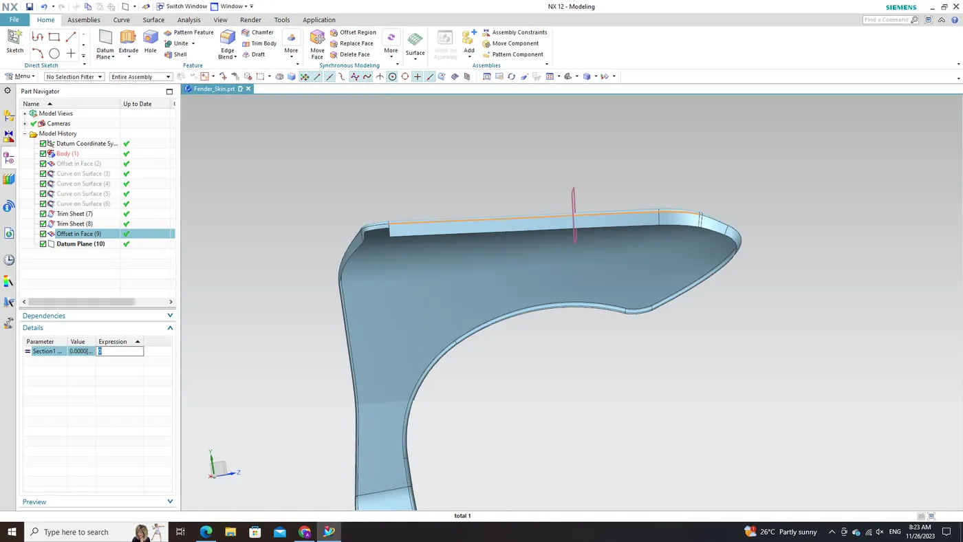
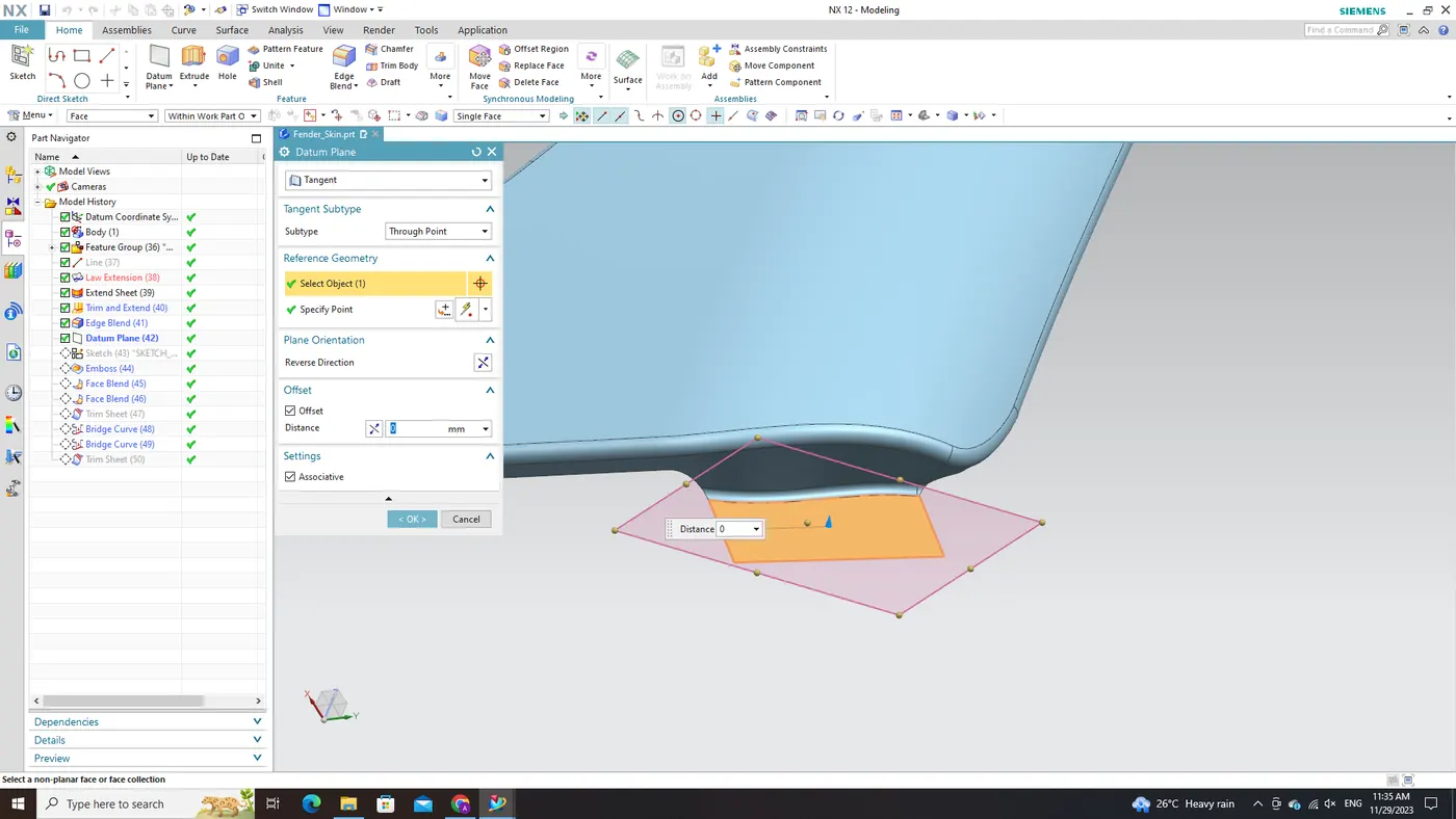
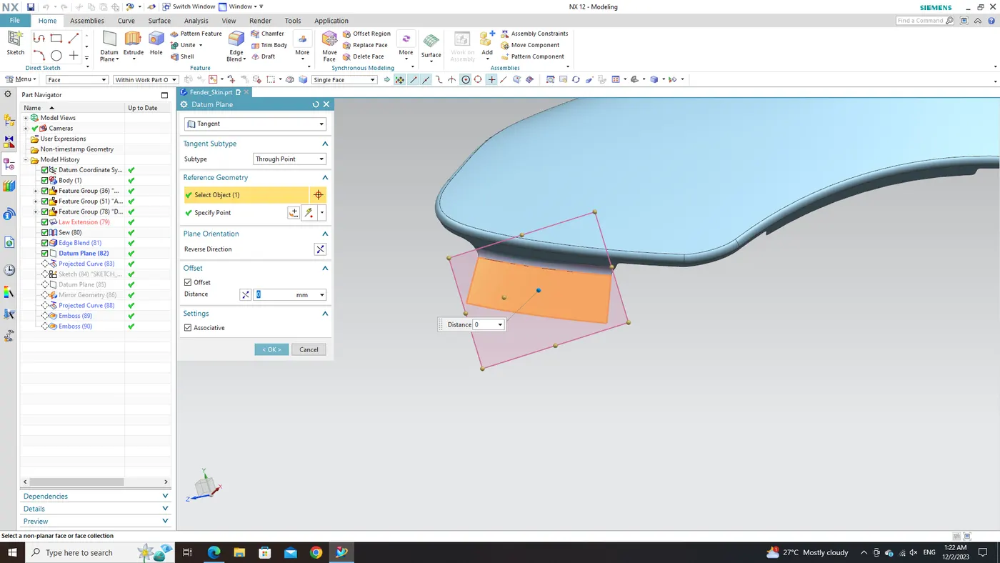
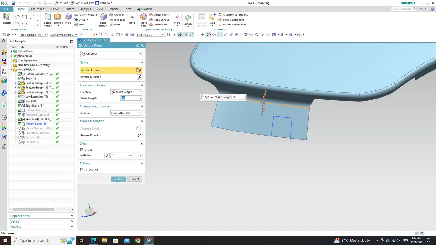
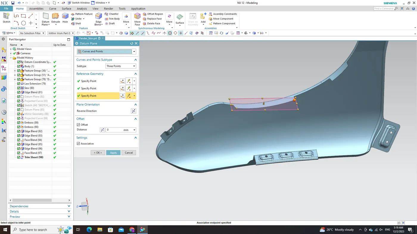
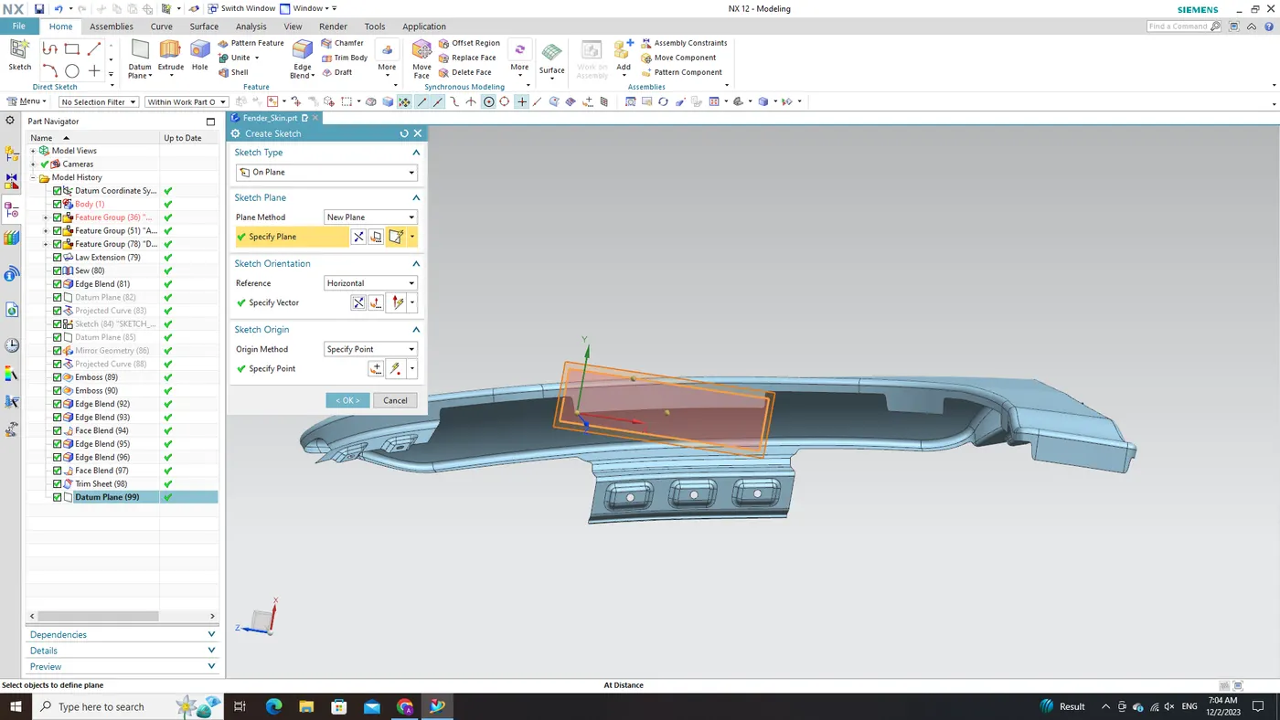
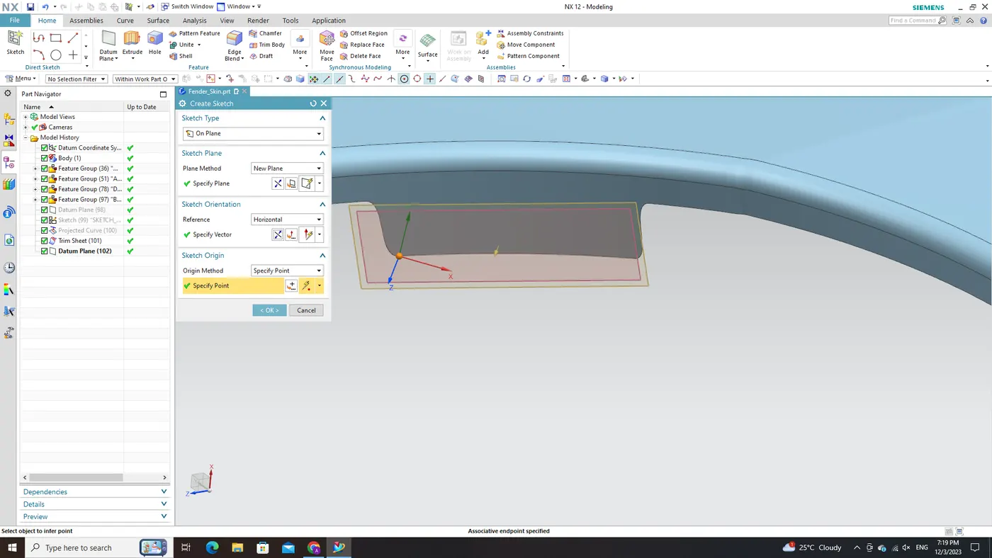
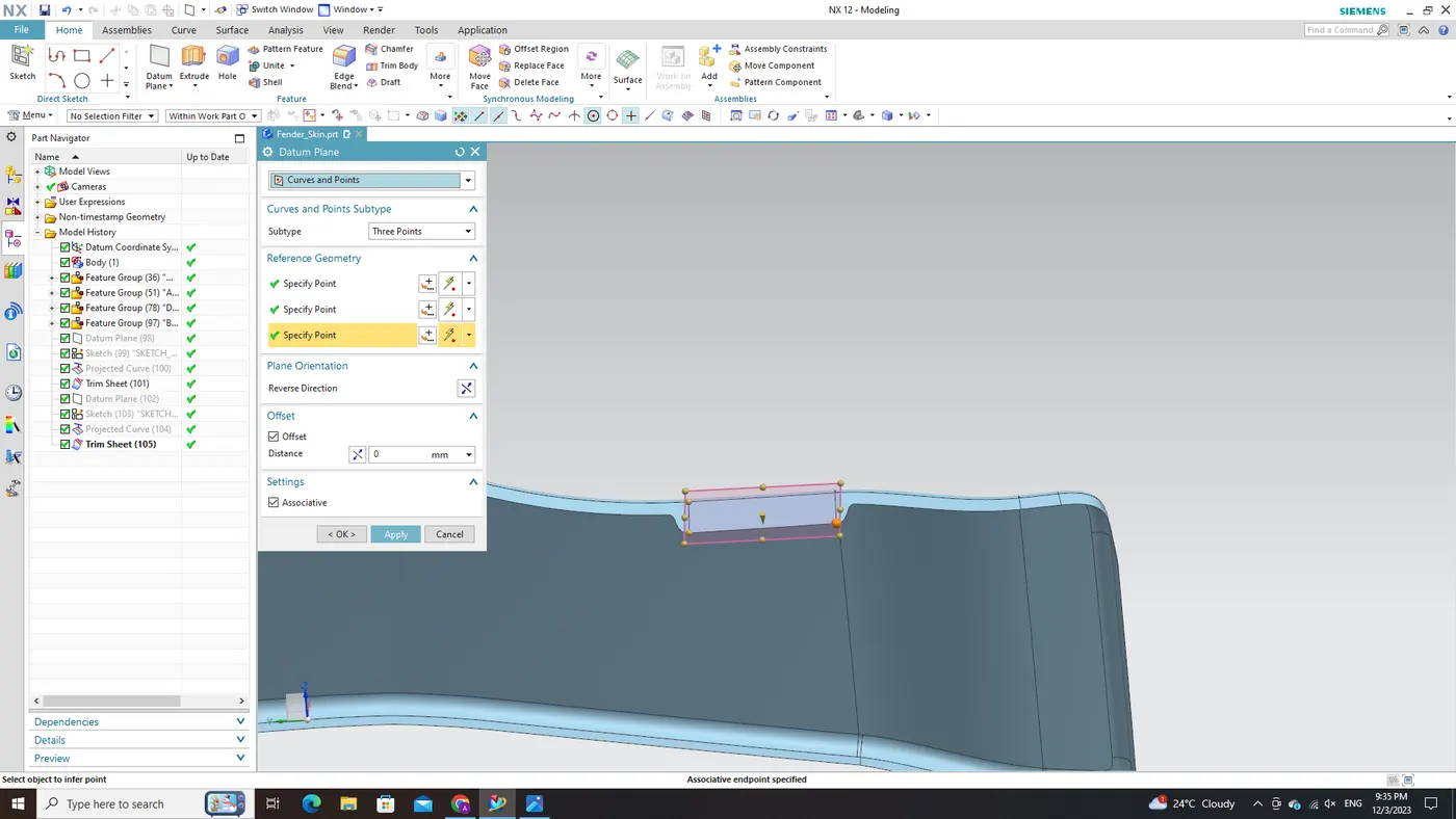
To ensure the correct orientation and serve as a reference for upcoming tasks, a Datum Plane will be established using the "Curves and Points" option within the Datum Plane creation module. By strategically choosing three points in alignment with our design parameters, we can precisely define this crucial datum plane.
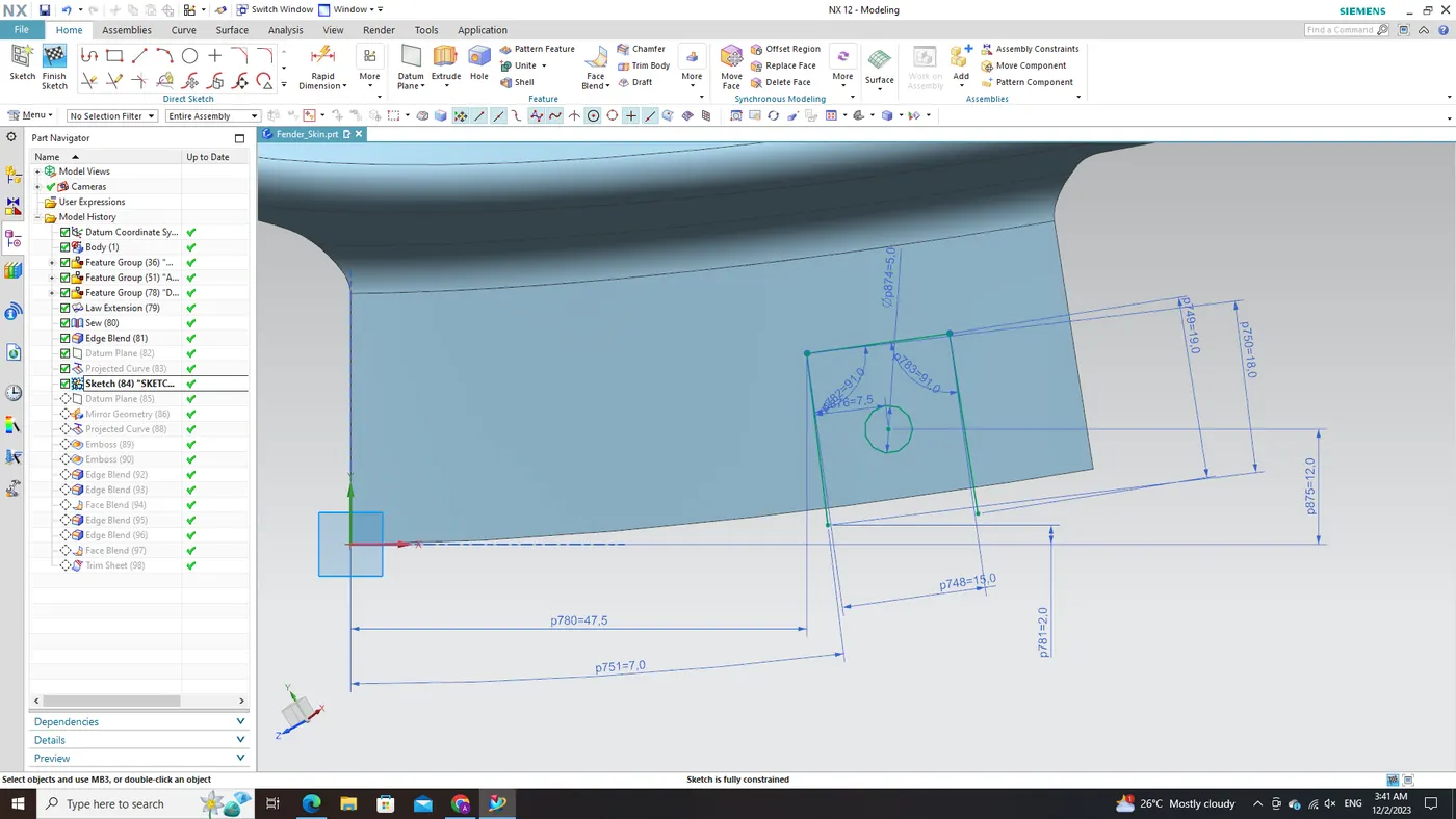
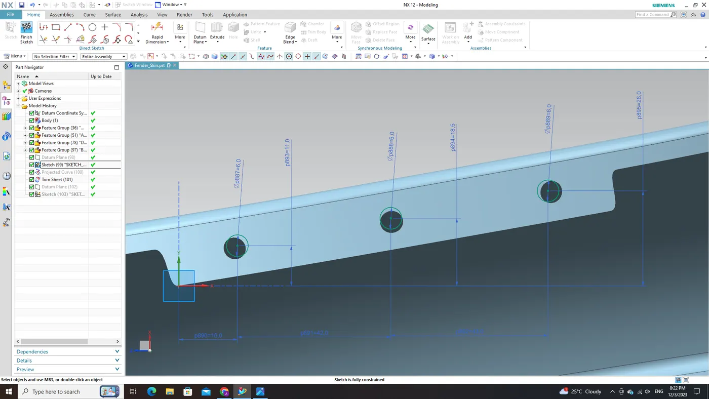
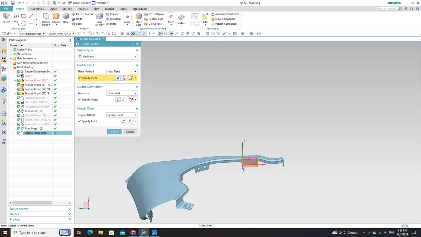
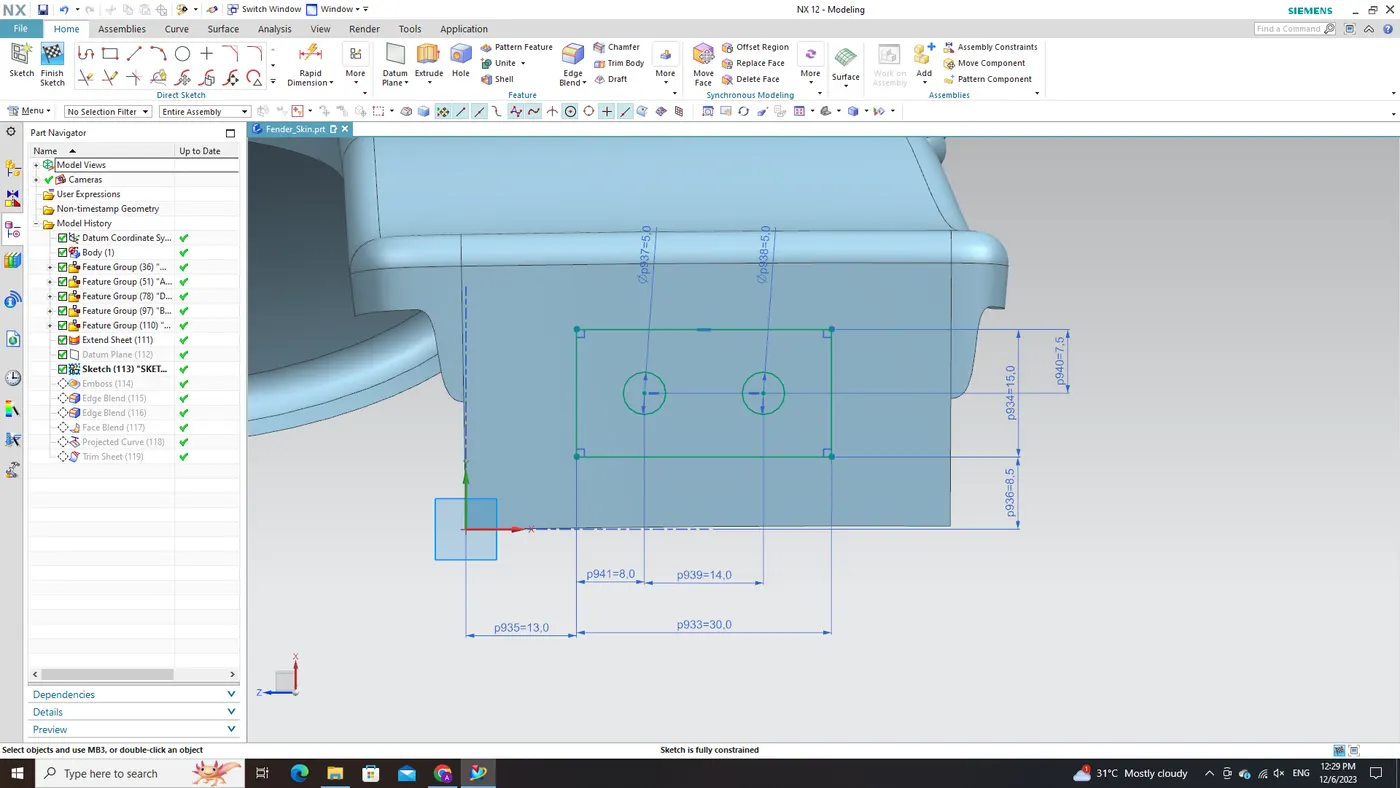
With the newly created datum plane serving as our reference framework, we move on to sketching both the embossed region and the hole for fastener placement. Adhering to best practices in sketching techniques within NX CAD software—such as incorporating dimensioning constraints and establishing geometric relationships among entities—ensures optimal control over our design intentions.
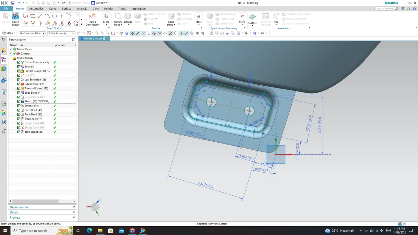
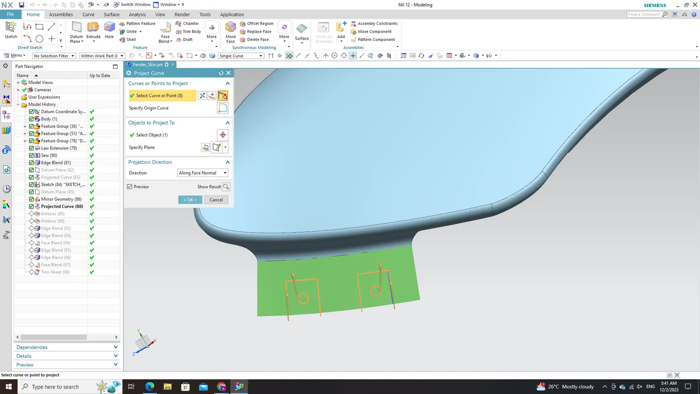
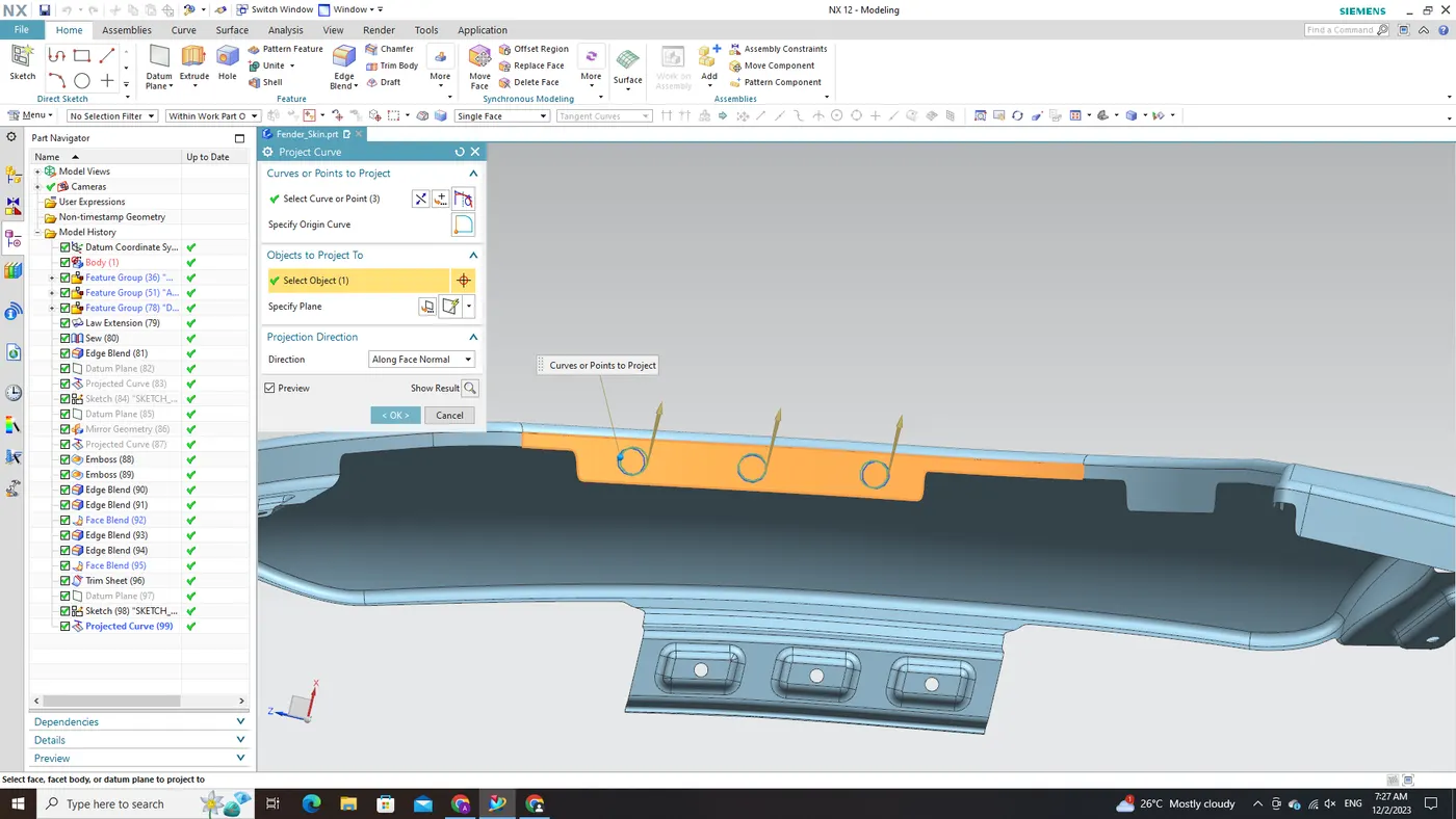
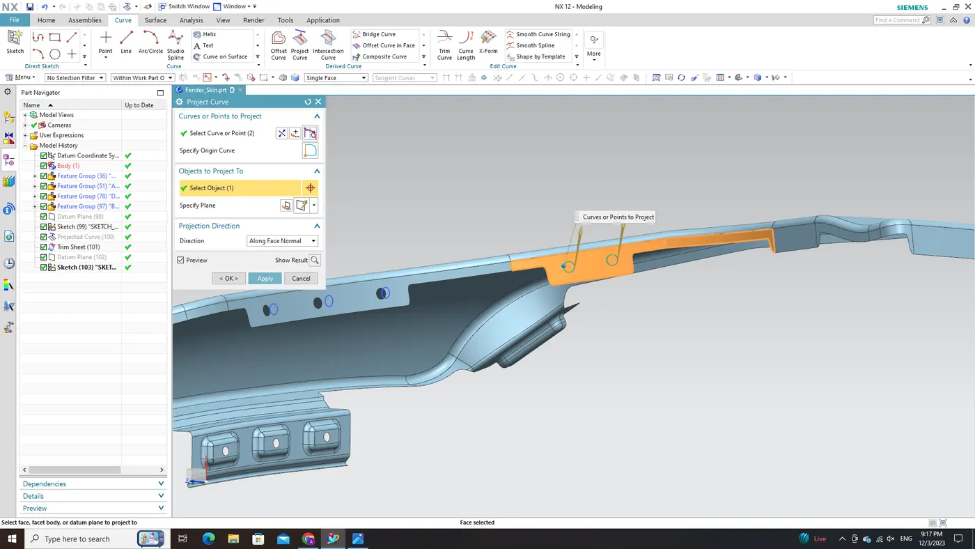
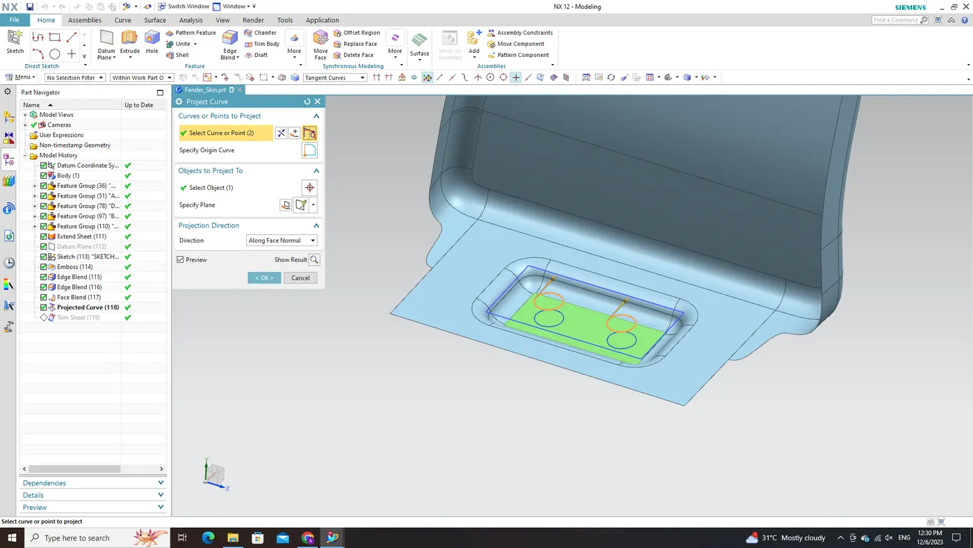
After ensuring complete constraint and validation in accordance with relevant specifications or standards, the sketched elements undergo projection onto their designated target surfaces. This projection process plays a vital role in accurately defining their positions while preserving necessary alignments with existing geometry.
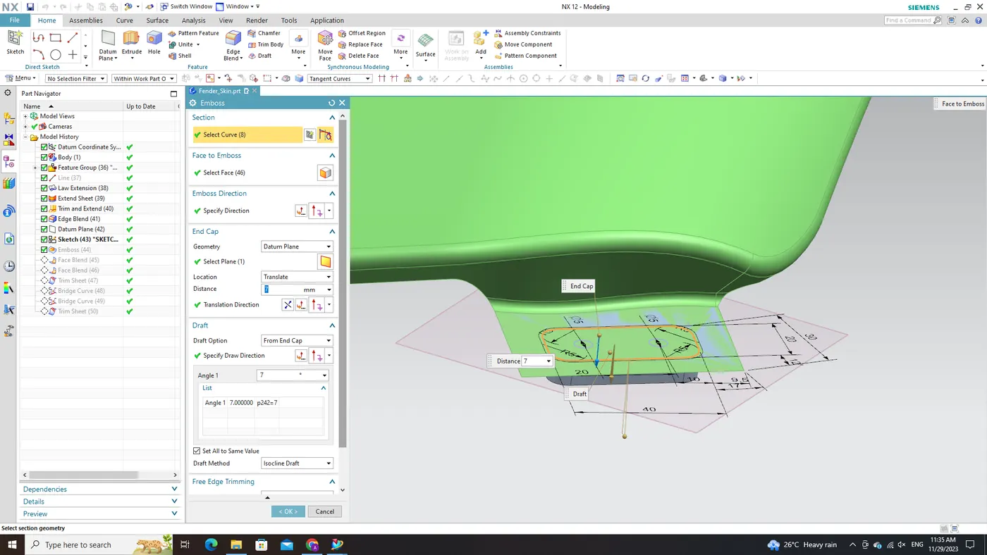
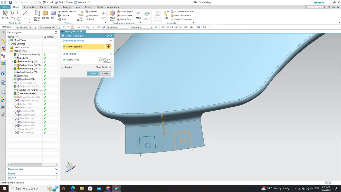
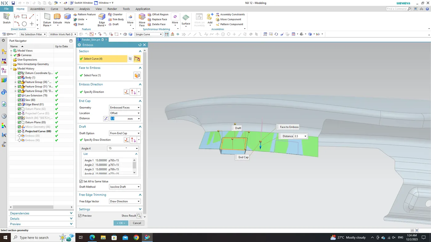
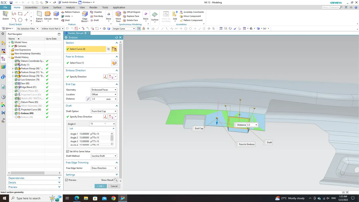
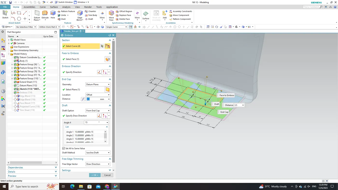
To bring the embossed region to fruition as per our design specifications, we employ the versatile 'Emboss' command within NX CAD. By specifying parameters such as depth or shape characteristics, this command facilitates the smooth creation of raised regions directly on selected surfaces. This feature not only introduces depth, dimension, and visual interest to the overall Fender mount design but also ensures compatibility with adjacent components and meets assembly requirements.
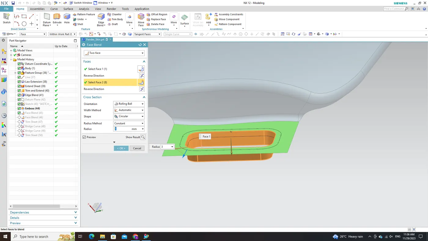
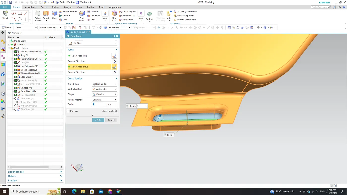
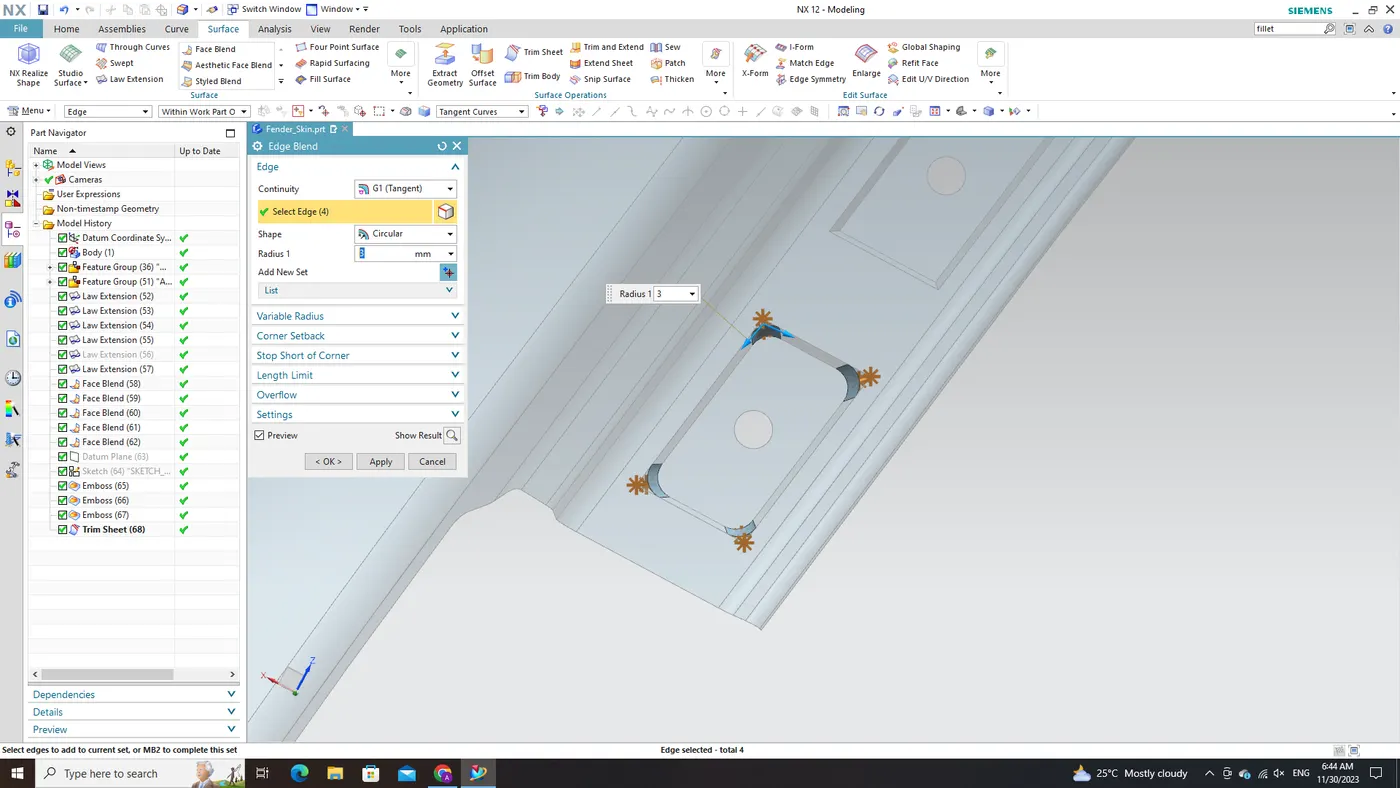
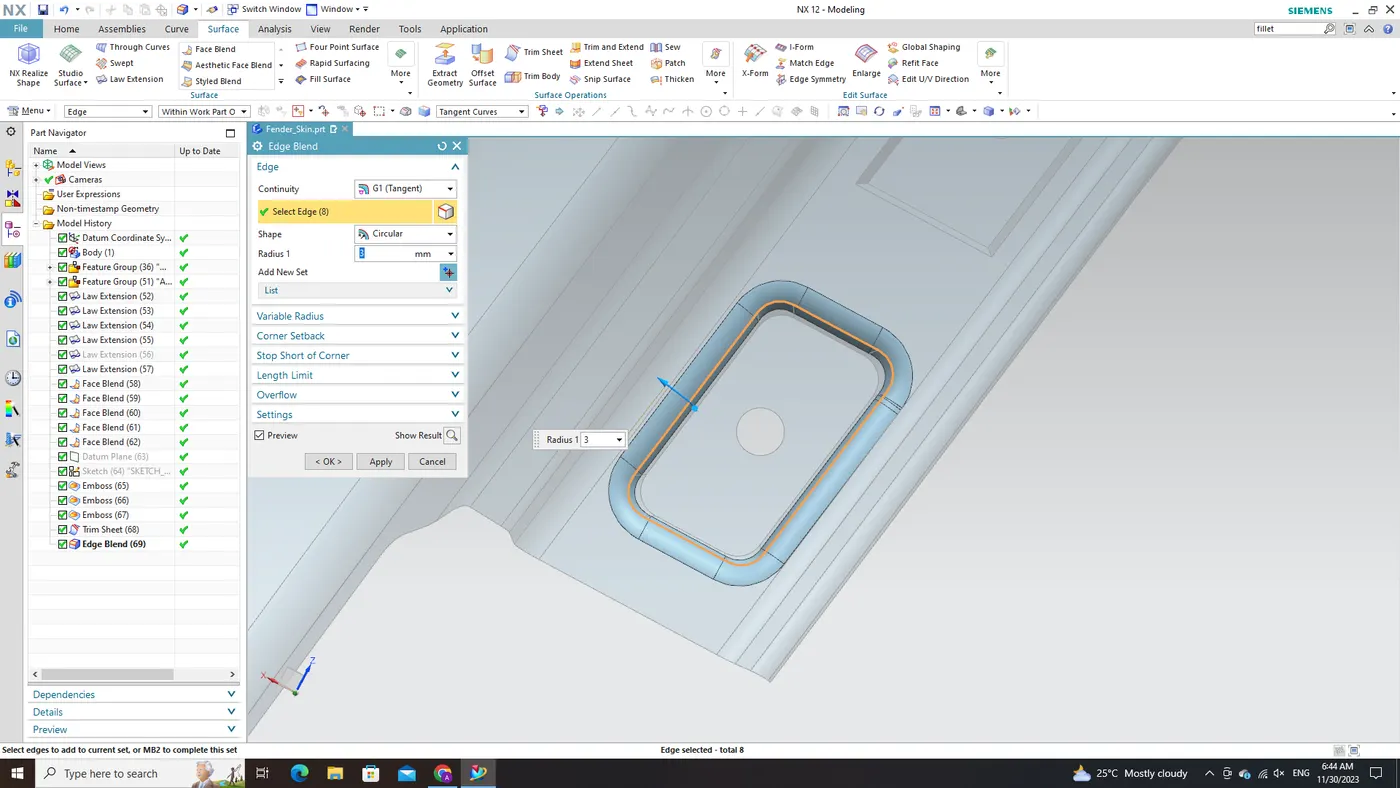
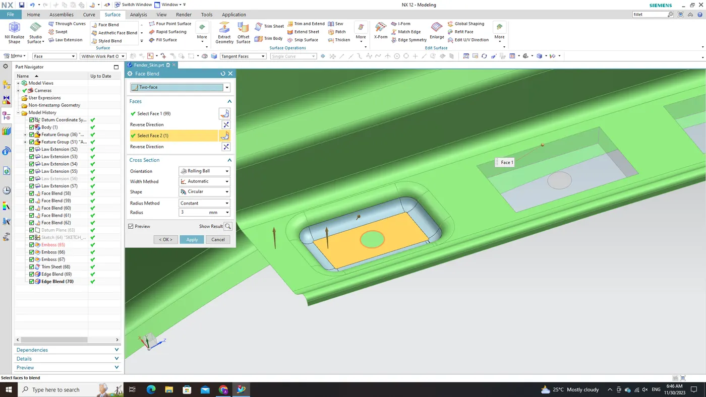
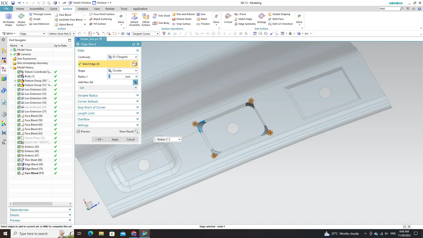
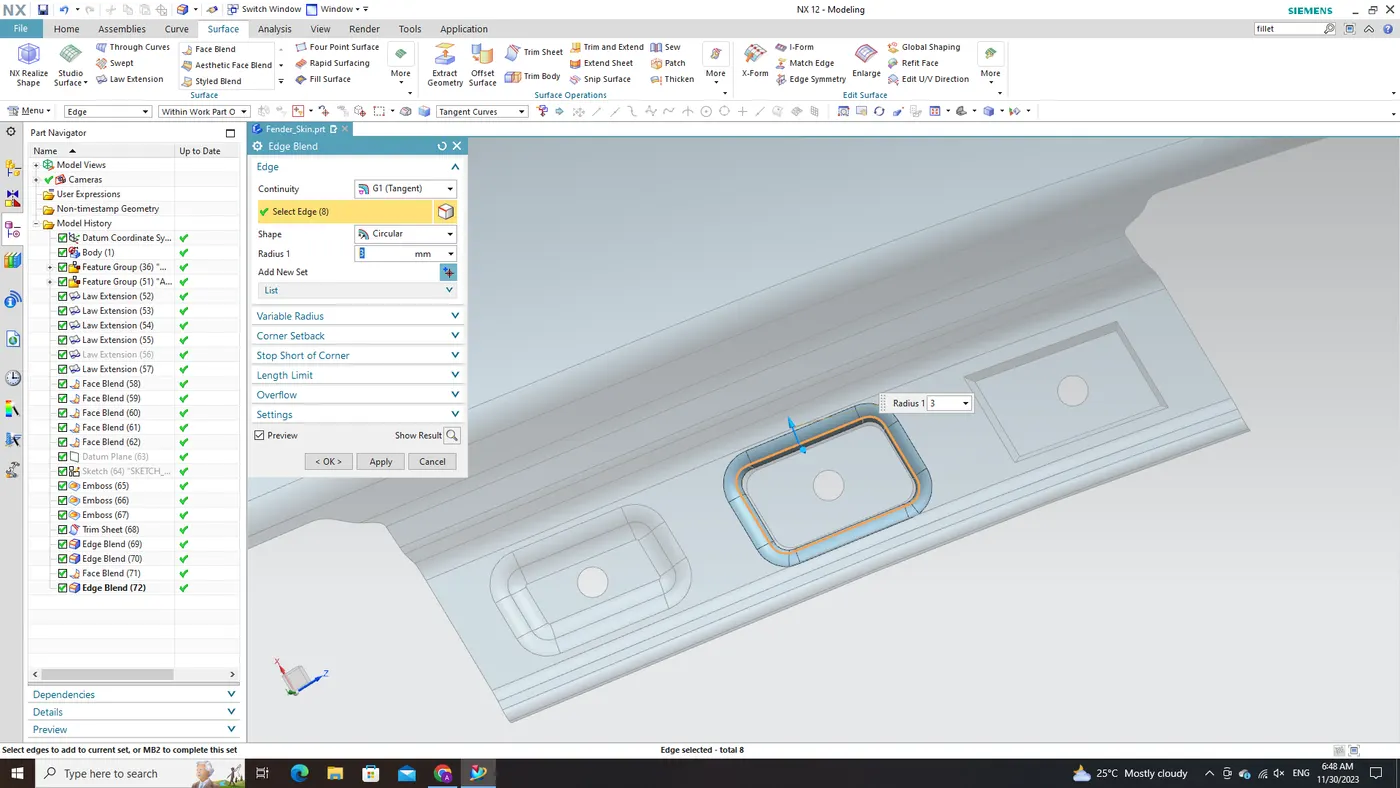
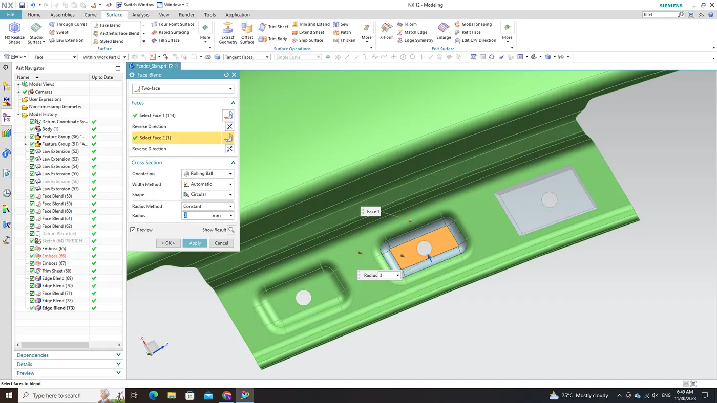
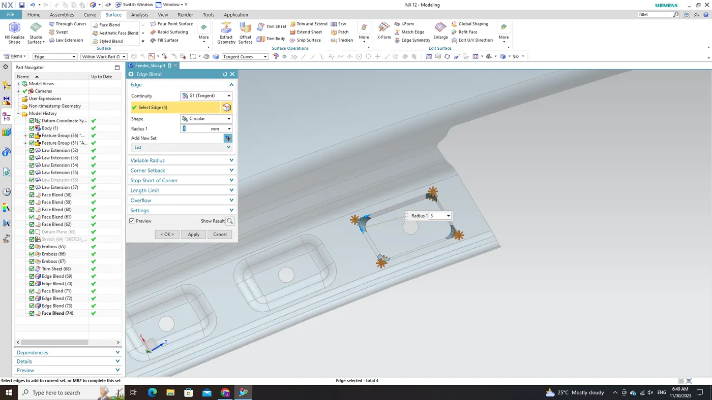
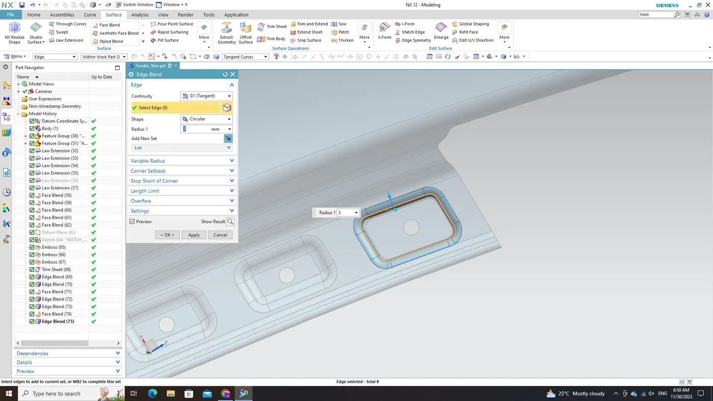
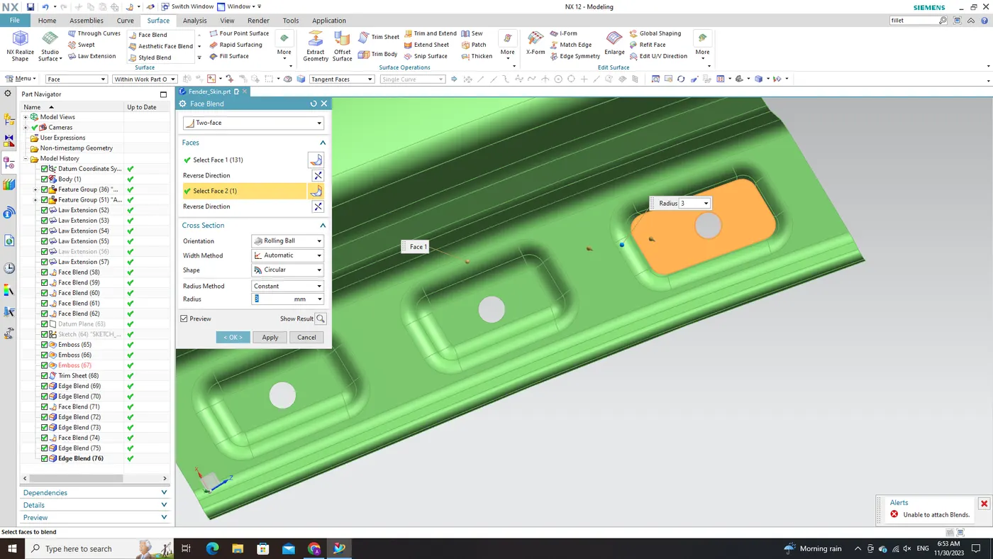
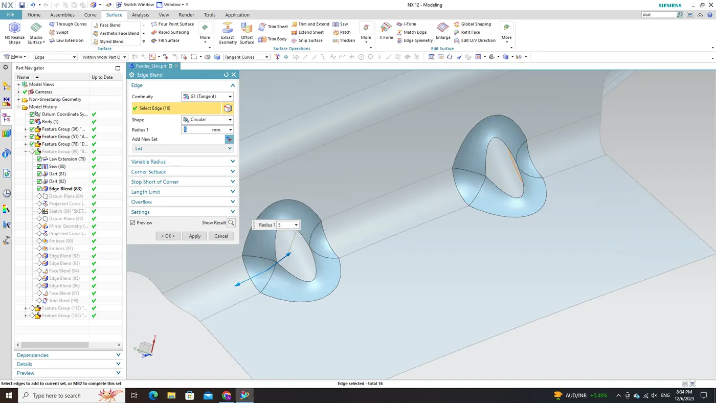
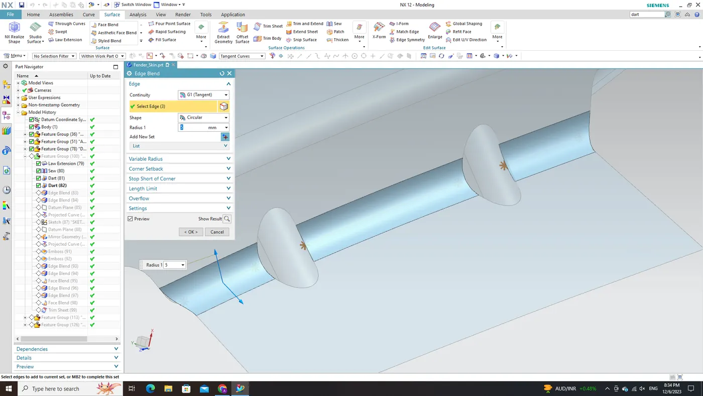
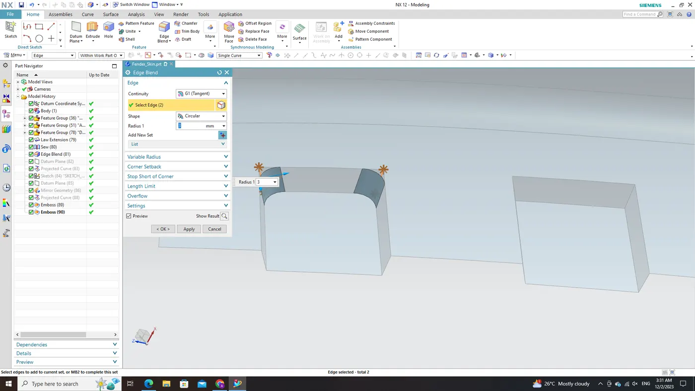
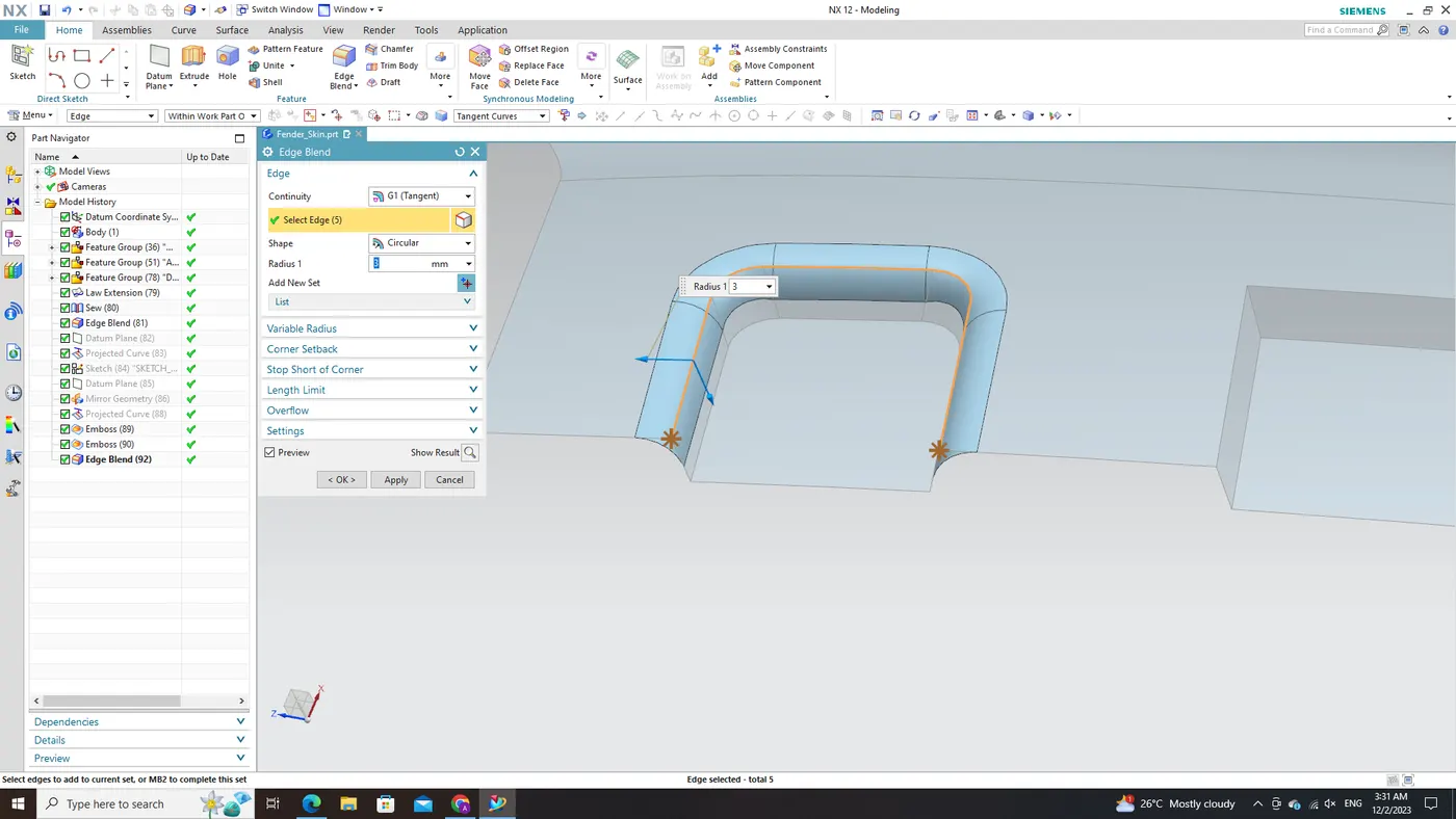
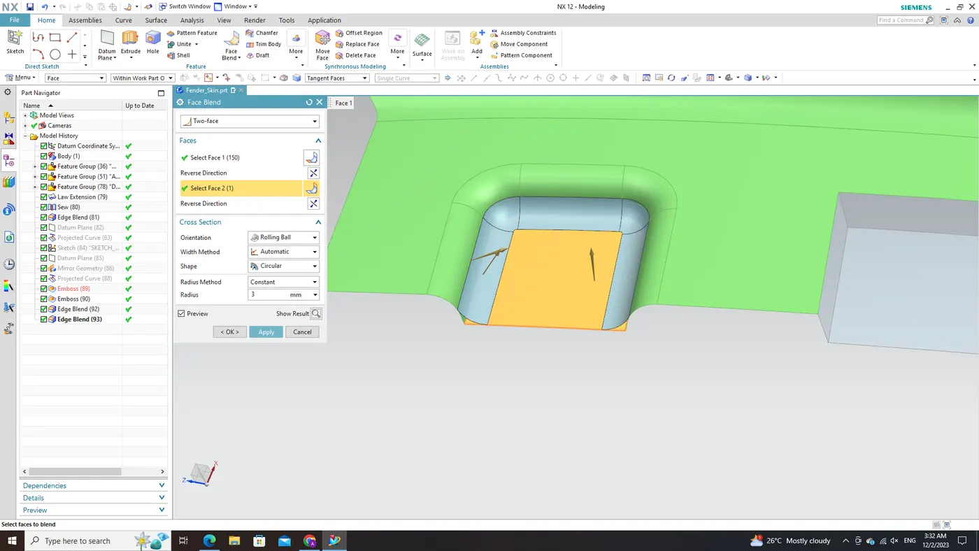
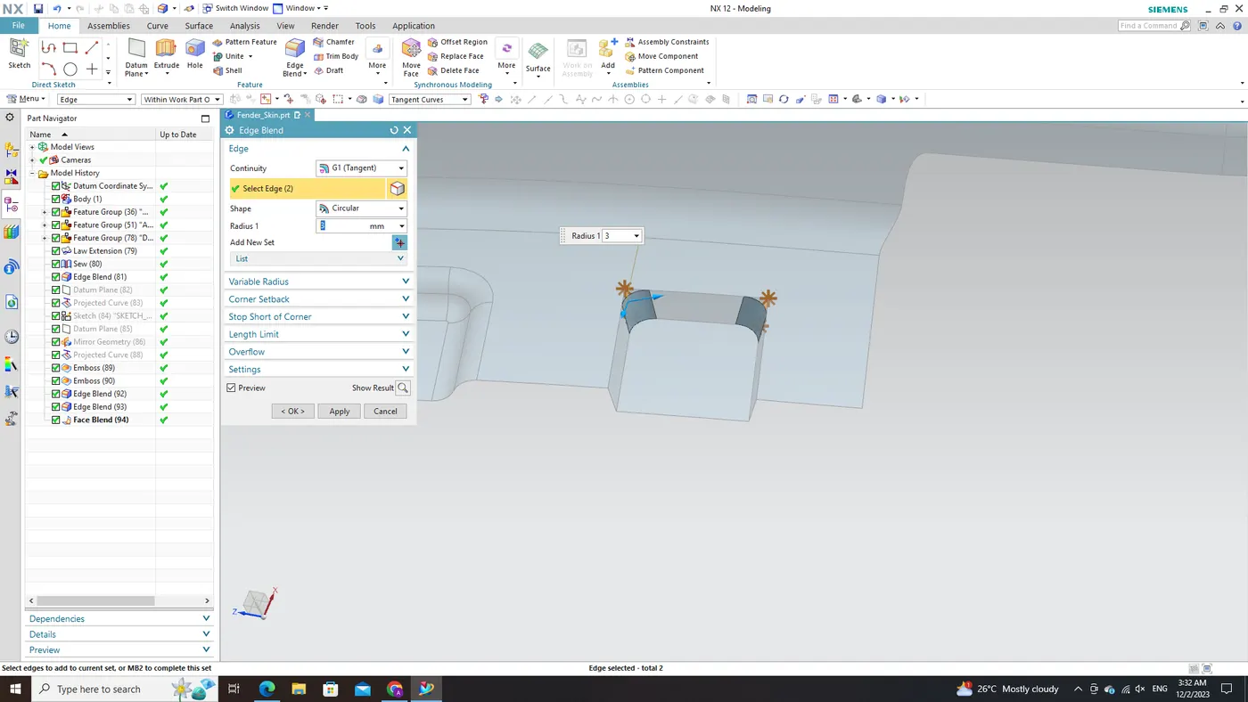
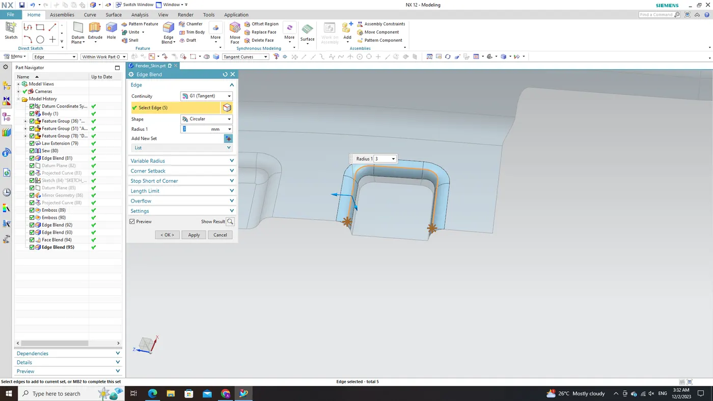
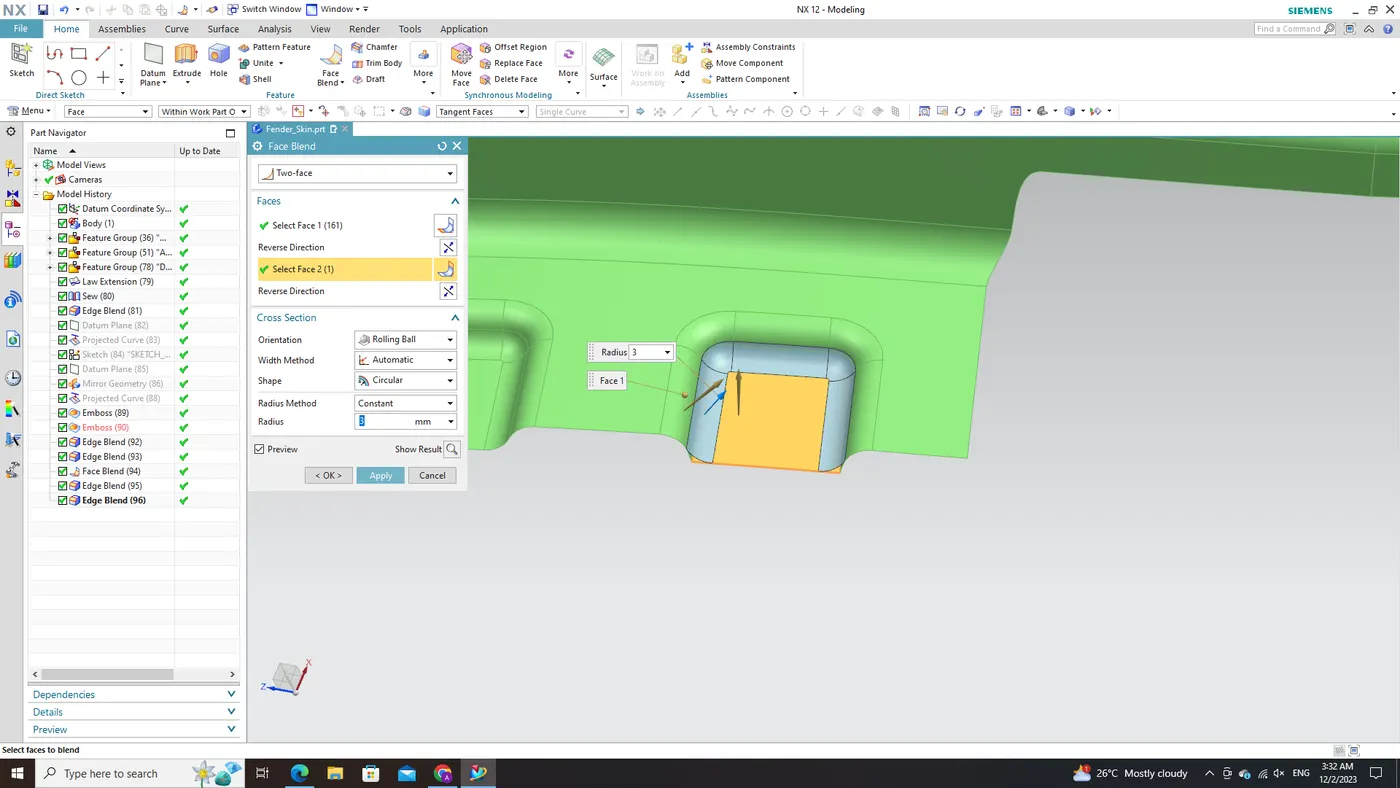
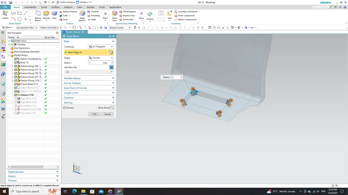
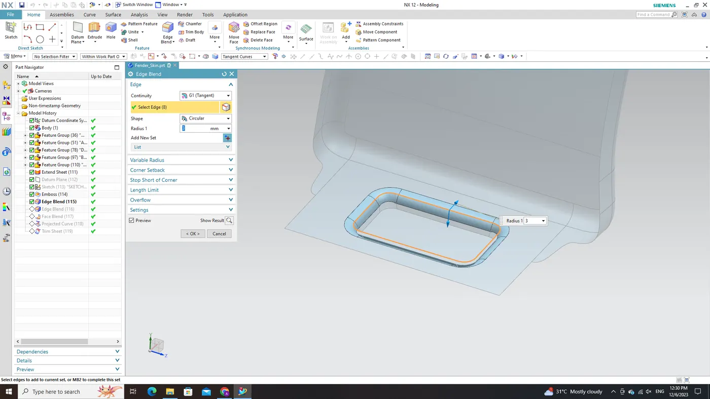
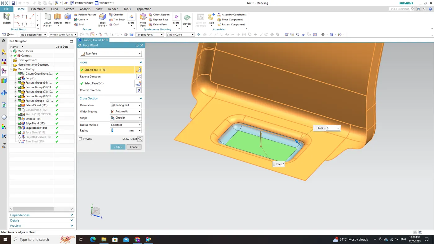
In the last phase, for seamless and aesthetically pleasing transitions across different regions and edges of the fender mounts, the 'Face Blend' and 'Edge Blend' commands come into play. These commands enable the creation of smooth transitions and fillets between adjacent faces and edges, respectively. Precisely defining blend radii or profiles ensures that the resulting blends align with design intent specifications, optimizing both functionality and visual appeal.
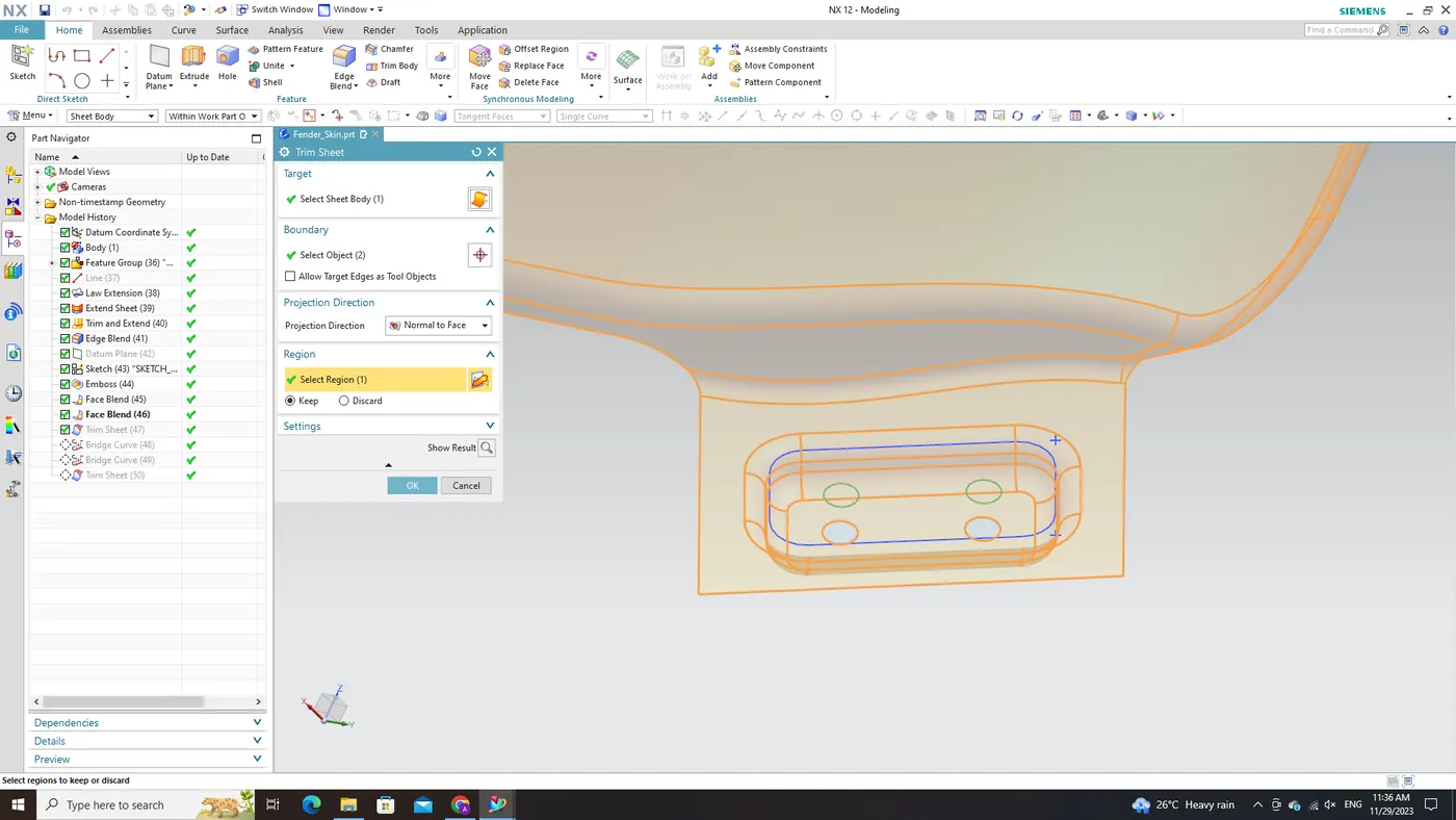
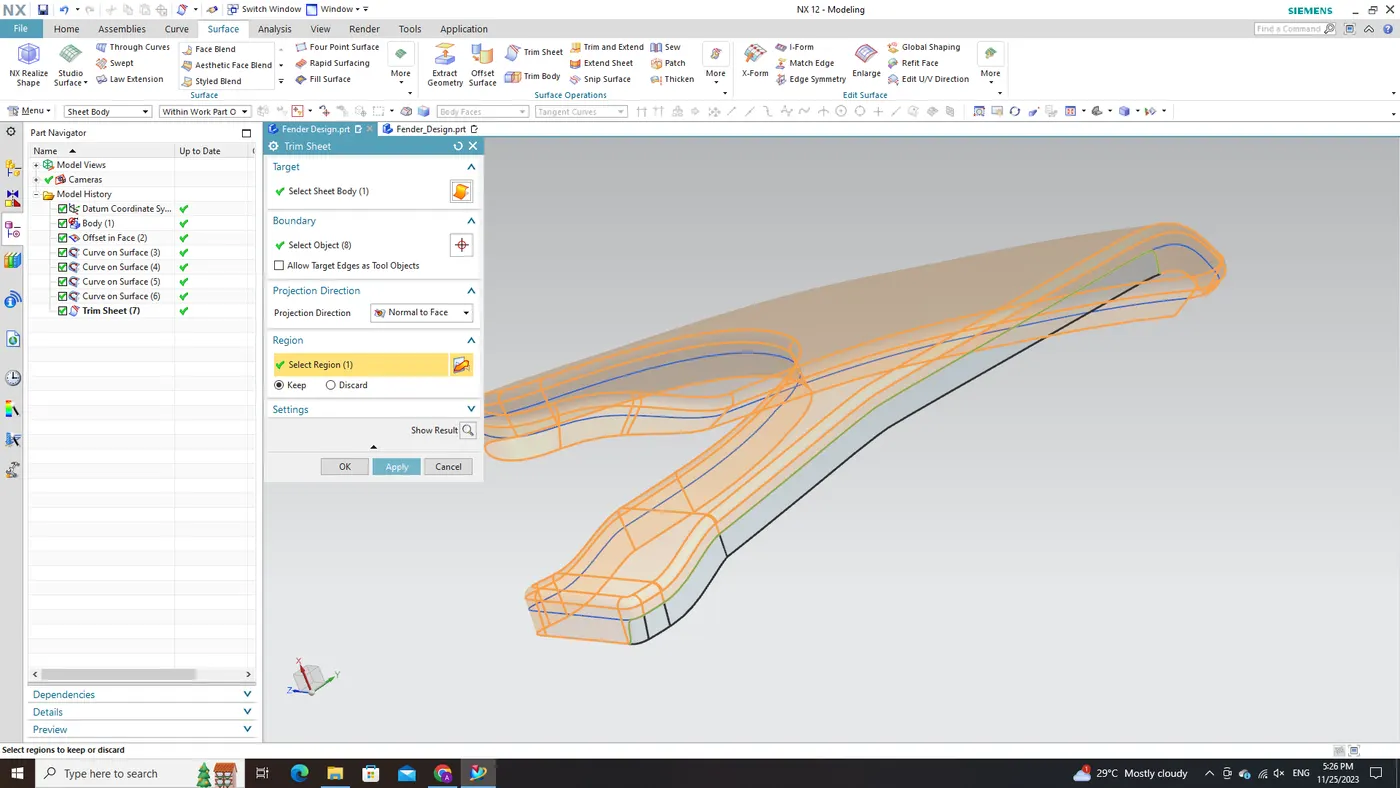
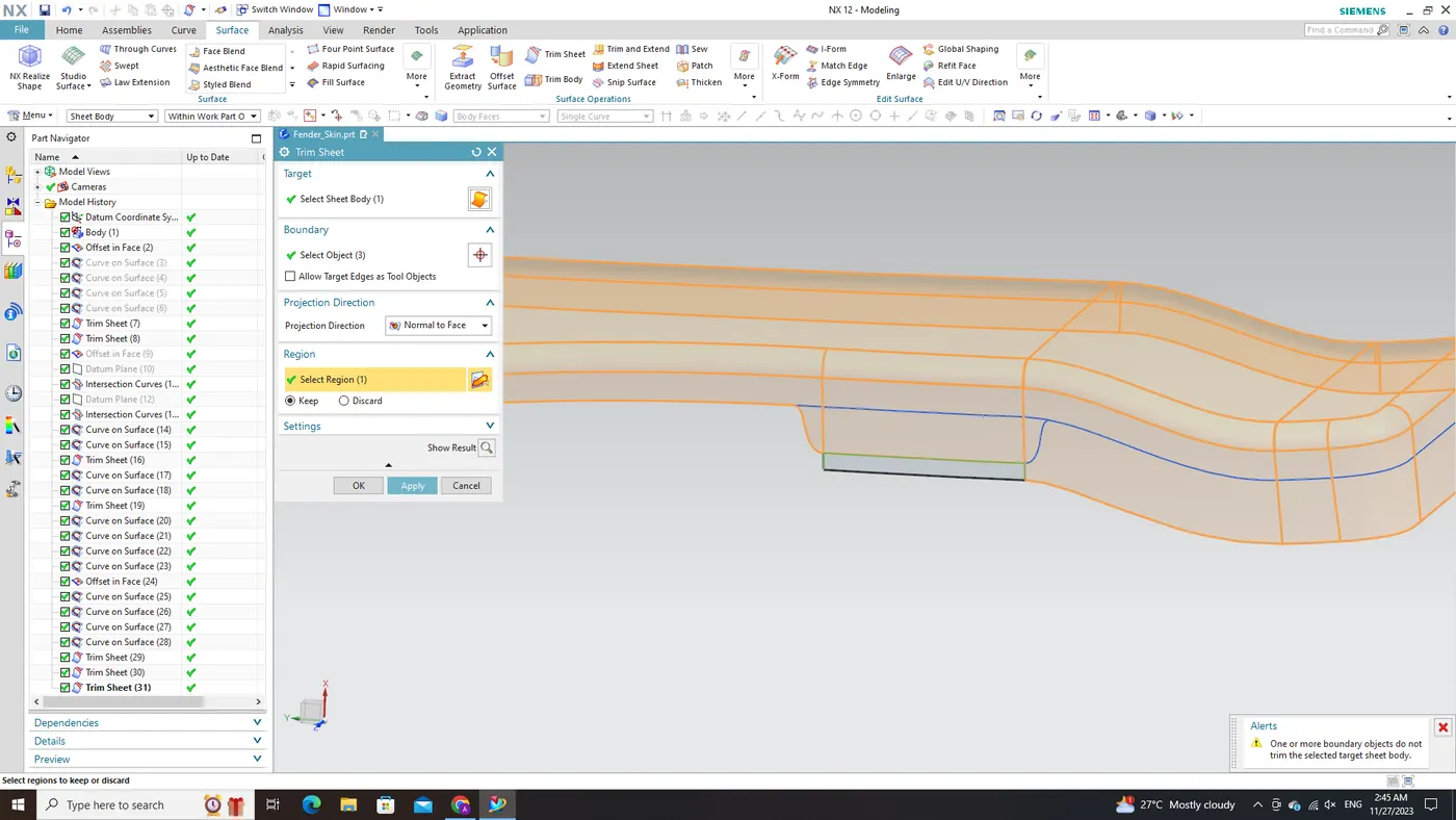
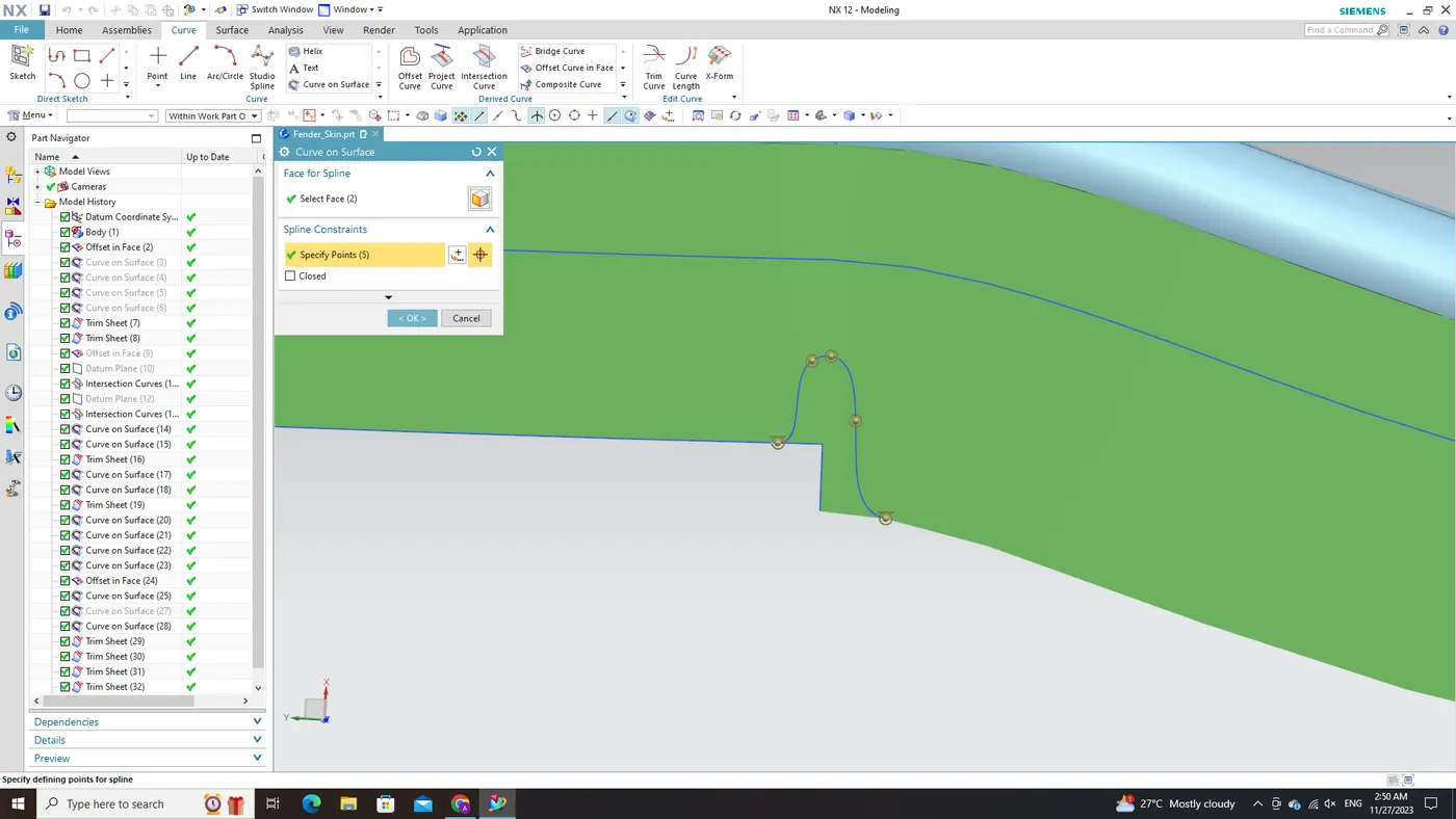
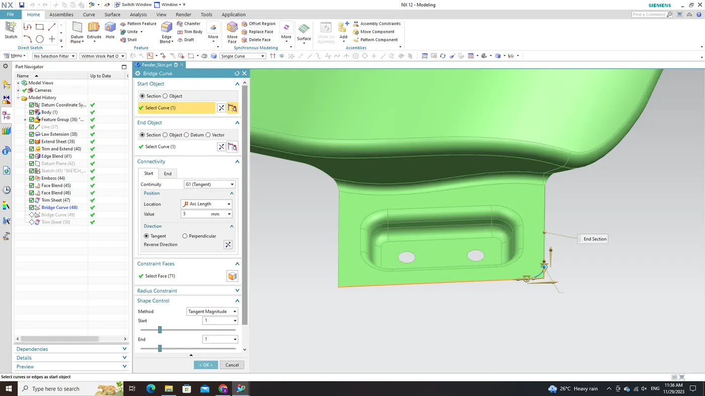
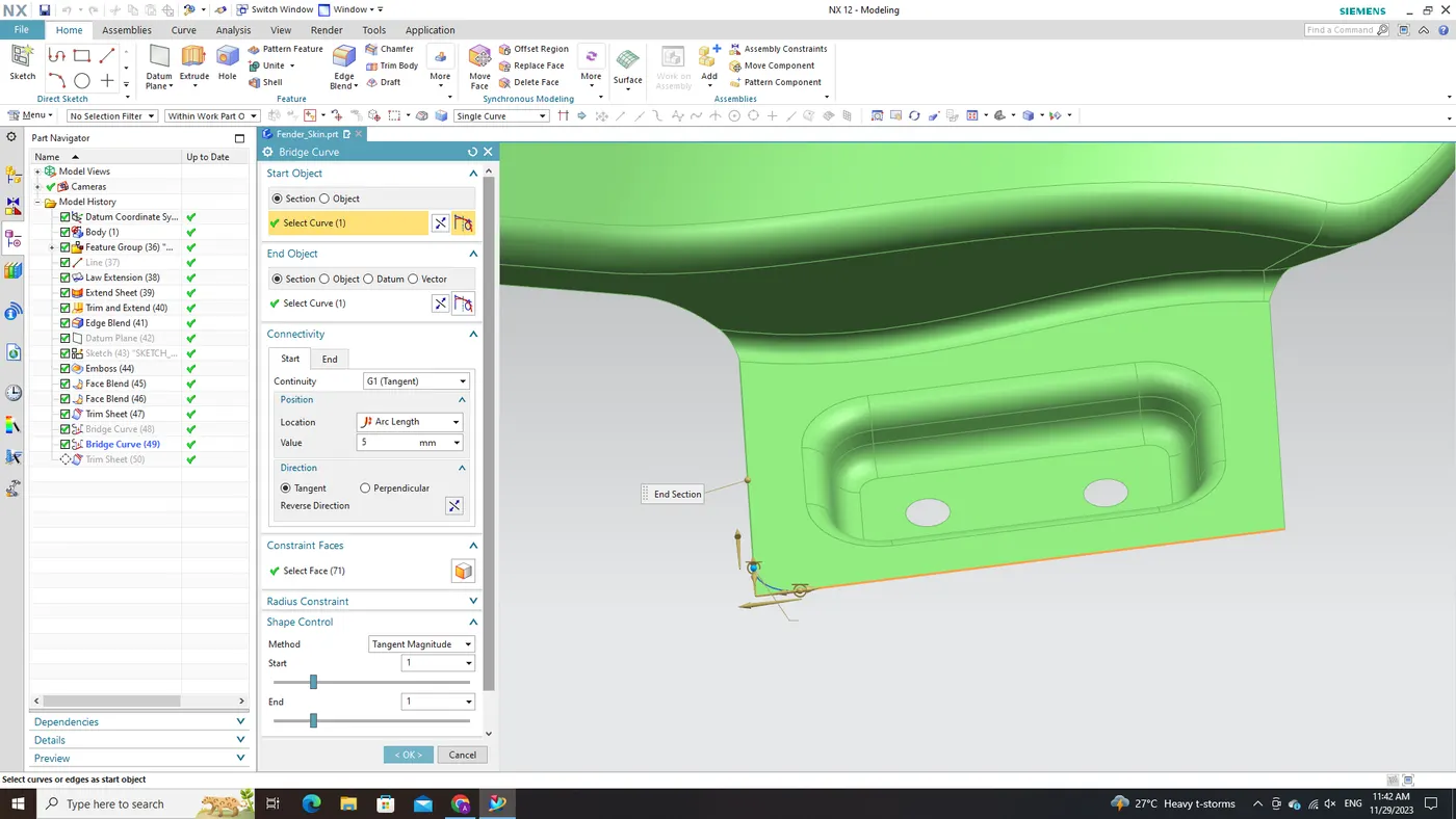
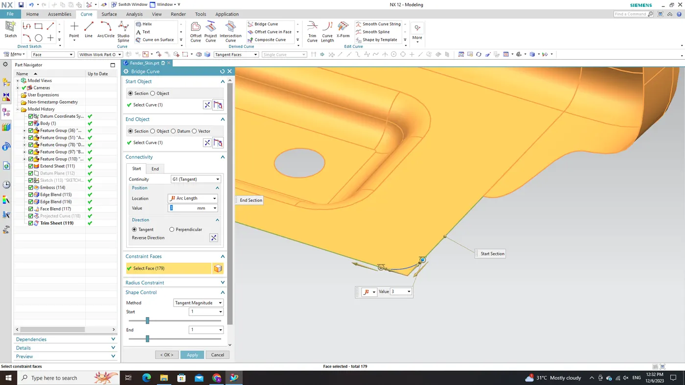
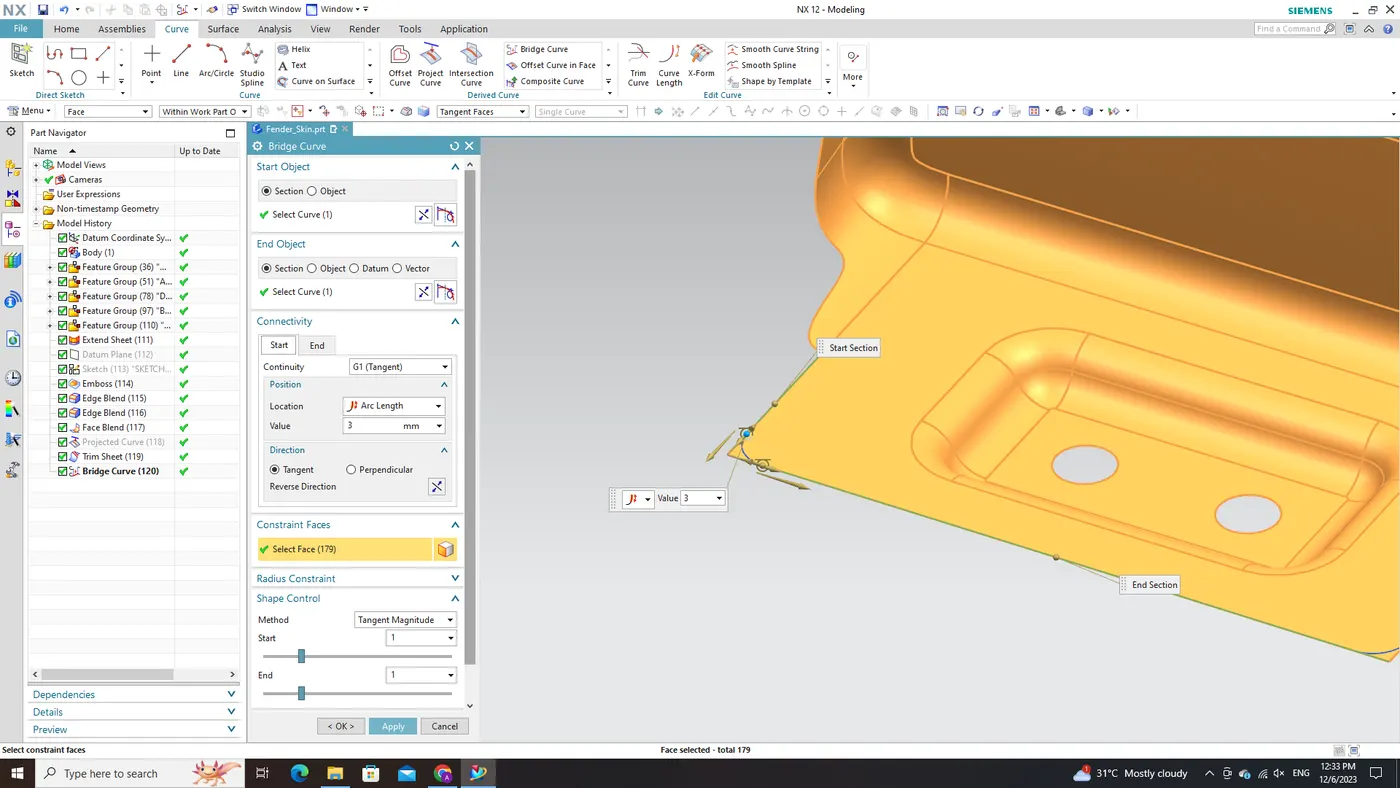
To eliminate sharp corners from our mount design, we will leverage the 'Bridge Curve' command. This command allows us to generate two curves that serve as guides for the removal of these sharp edges. Within the NX CAD software, I utilized the 'Bridge Curve' command to create these curves, selecting appropriate reference points and defining desired shapes. These bridge curves serve as smooth transitions between different sections of our mount.
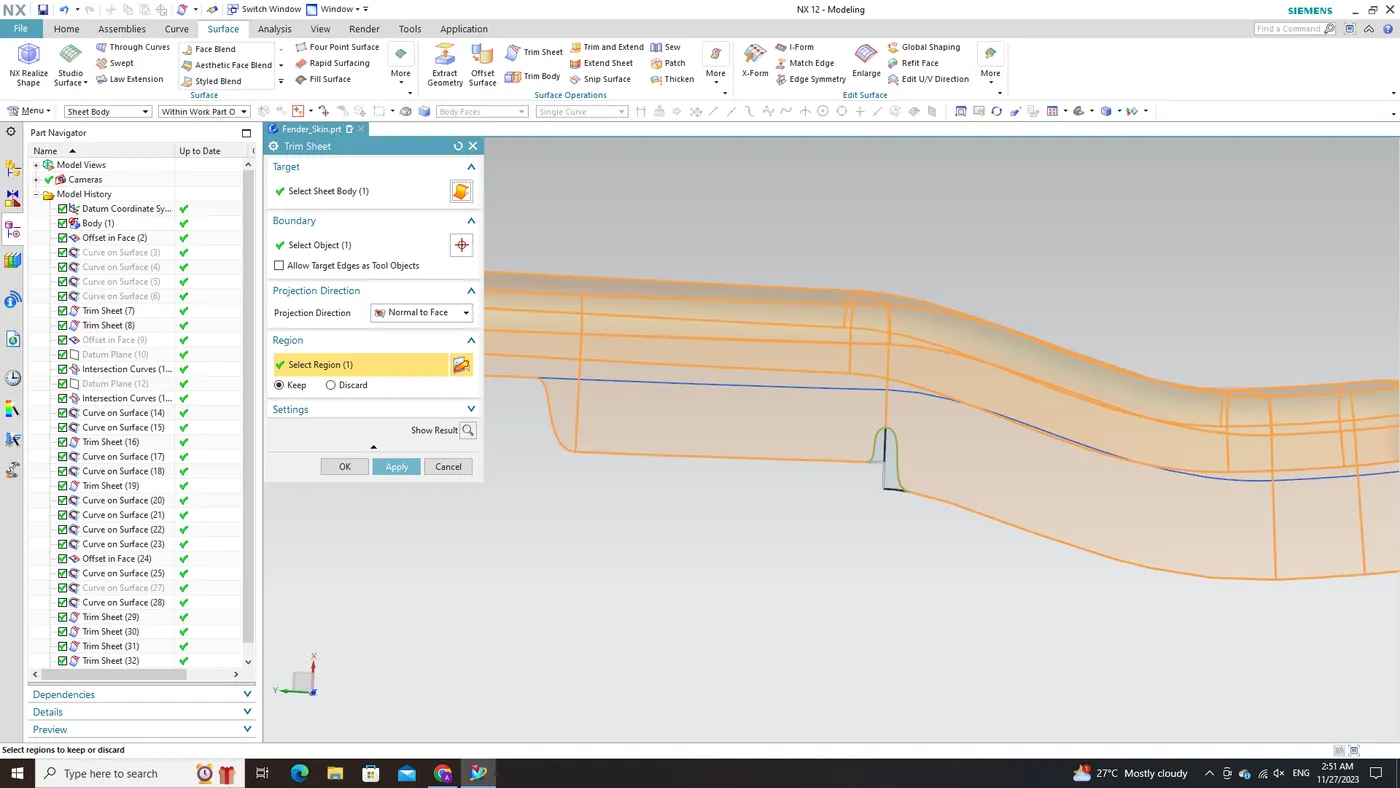
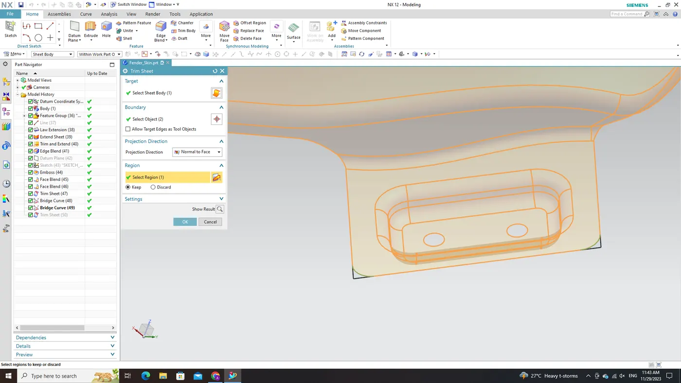
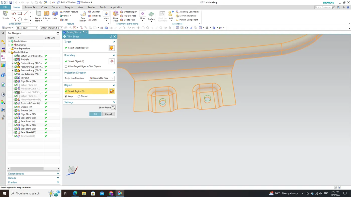
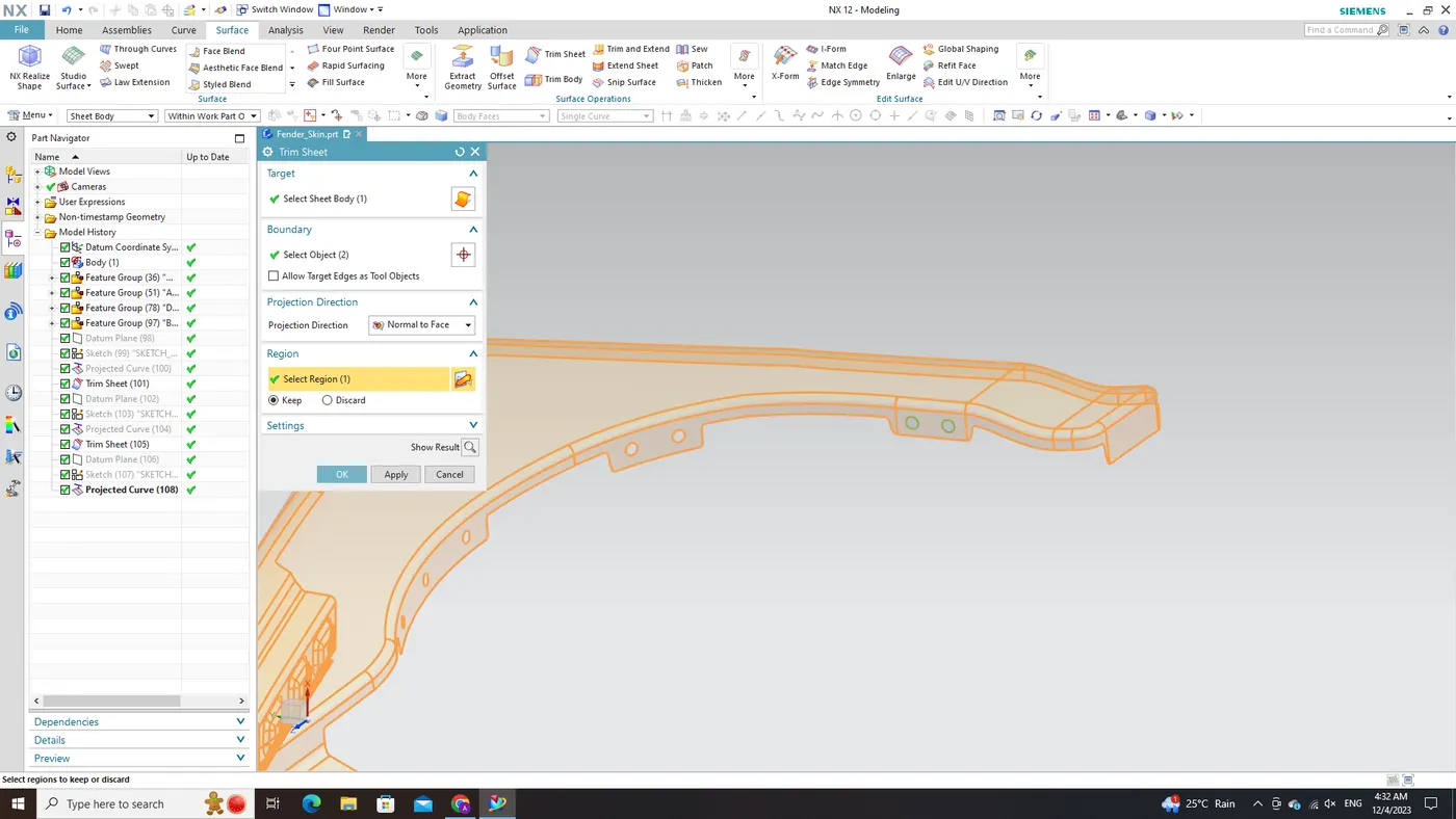
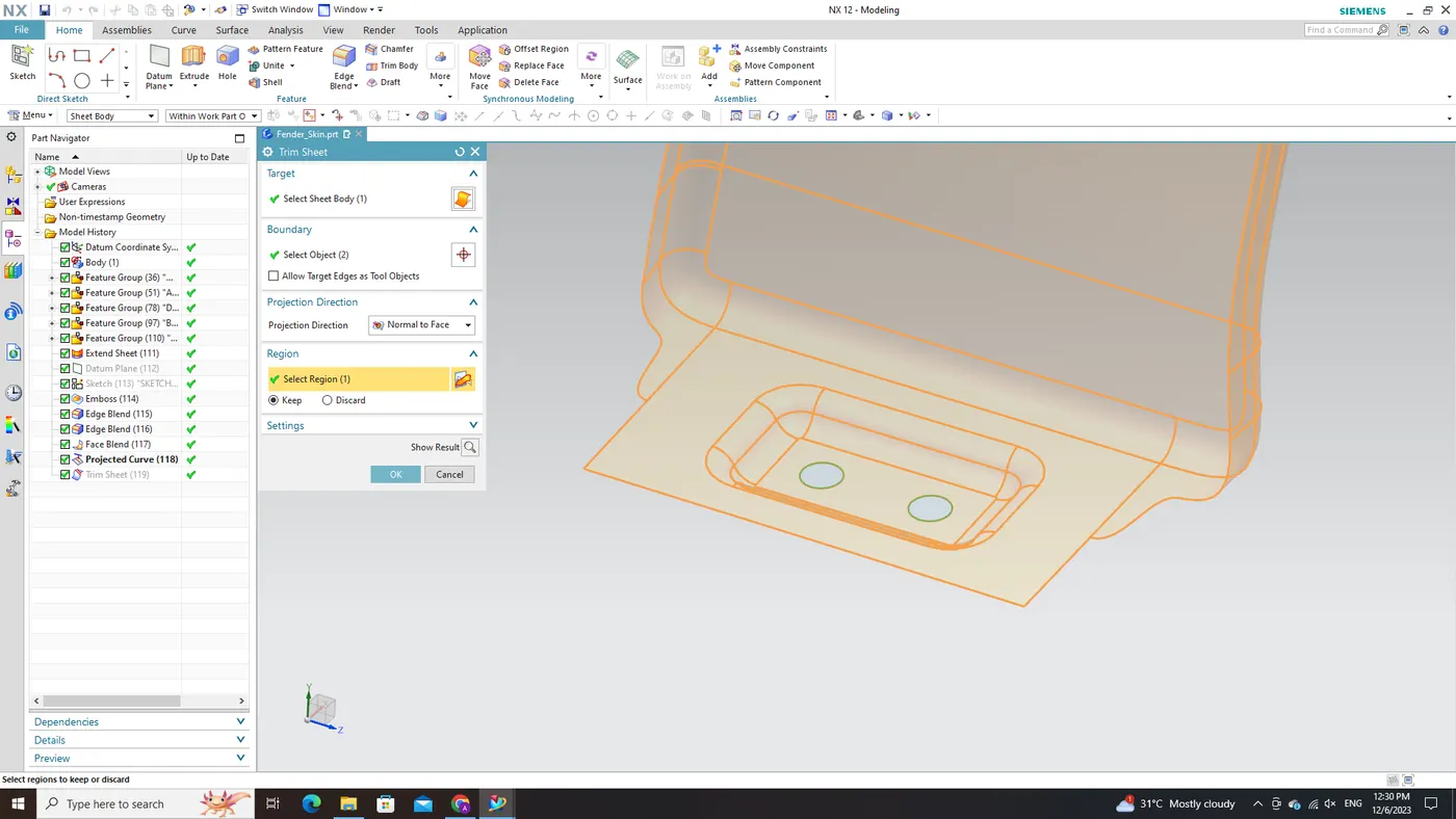
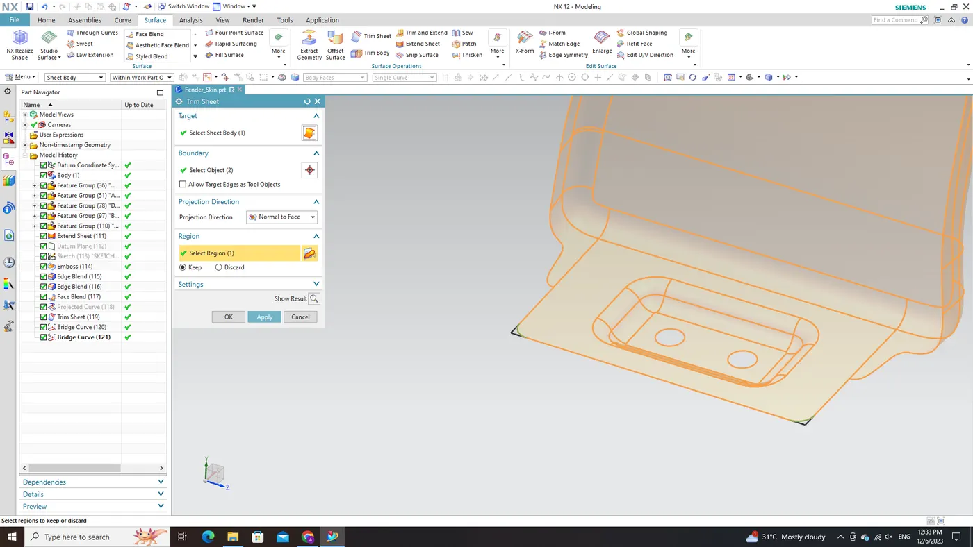
Subsequently, the 'Trim Sheet' command is applied to these bridge curves to eliminate the unwanted sharp corners. By carefully selecting and implementing this command, we effectively trim away excess material while preserving continuity and maintaining the overall integrity of our design.
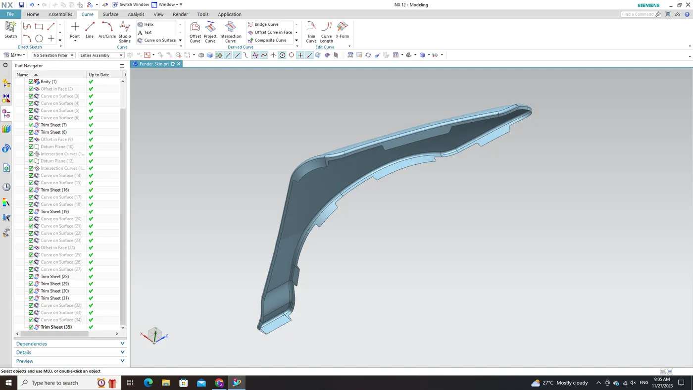
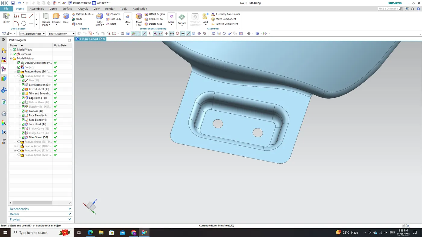
By following these steps—utilizing 'Bridge Curve' to create transitional curves and applying 'Trim Sheet' to those bridges—we achieve a refined fender mounting surface with eliminated sharp corners. This process enhances both aesthetics and functionality, ensuring seamless integration with surrounding components.
Drip Mount Area:
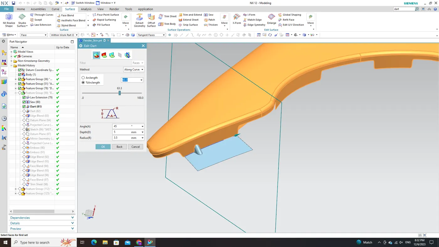
After successfully concluding the A-pillar mount design phase using NX CAD software, attention is directed towards developing a proficient Drip Area Mount. Recognizing the significance of alignment and stability in this specific region, we leverage NX CAD's advanced tools and features for precise curvature matching and surface creation. This incorporates G1 continuity controls to guarantee a smooth integration between the fender top panel and surrounding body structures. This crucial step not only ensures proper fitment but also elevates both the functionality and aesthetics associated with the Fender design.
In crafting the Drip Area Mount for the fender, our reference point is the Master Section image provided as a visual guide. While it may not be directly importable into NX CAD software, we can meticulously analyze and interpret its details to faithfully replicate the desired features with precision. Analyzing the Master Section thoroughly examine the shared Master Section image below. Pay close attention to curvature profiles, angles, and specific design requirements indicated within it.
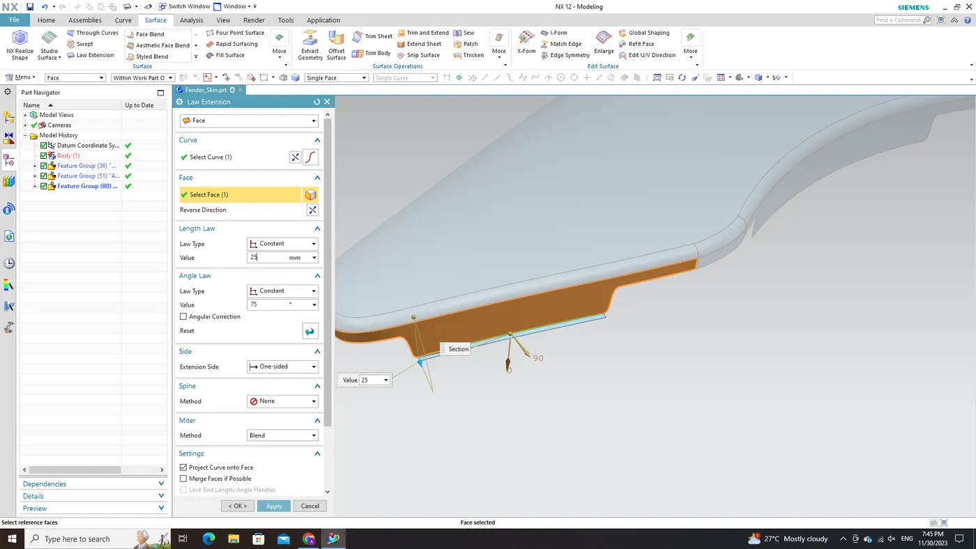
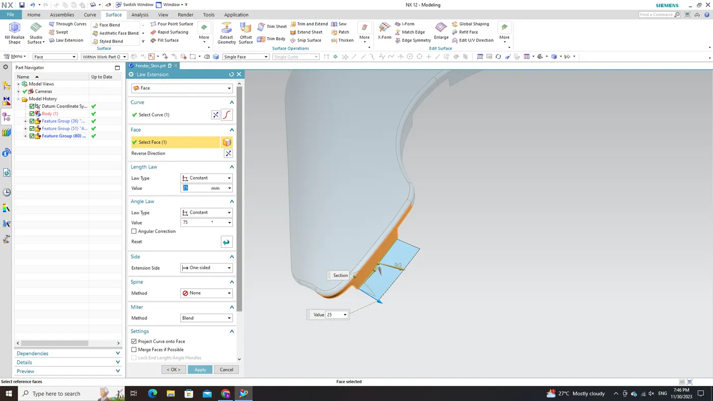
Utilizing insights from the Master Section analysis, employ NX CAD's Law Extension command to extend surfaces at specified angles, aligning with the curvature depicted in the image. Apply these commands strategically and with precision across various sections of our design.
After extending surfaces using Law Extension commands, proceed to employ 'Edge Blend' and 'Face Blend' commands in NX CAD software for blending purposes. These operations facilitate smooth transitions between extended surfaces, eliminating sharp edges or discontinuities. By meticulously following this step-by-step procedure—analyzing and interpreting the provided Master Section image, extending surfaces with Law Extension commands based on observed curvature, and applying necessary blends through 'Edge Blend' and 'Face Blend' commands—we can effectively craft a Drip Area Mount for automotive fenders within NX CAD software.
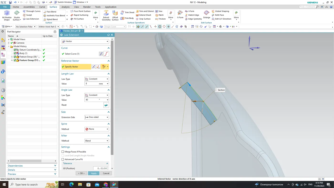
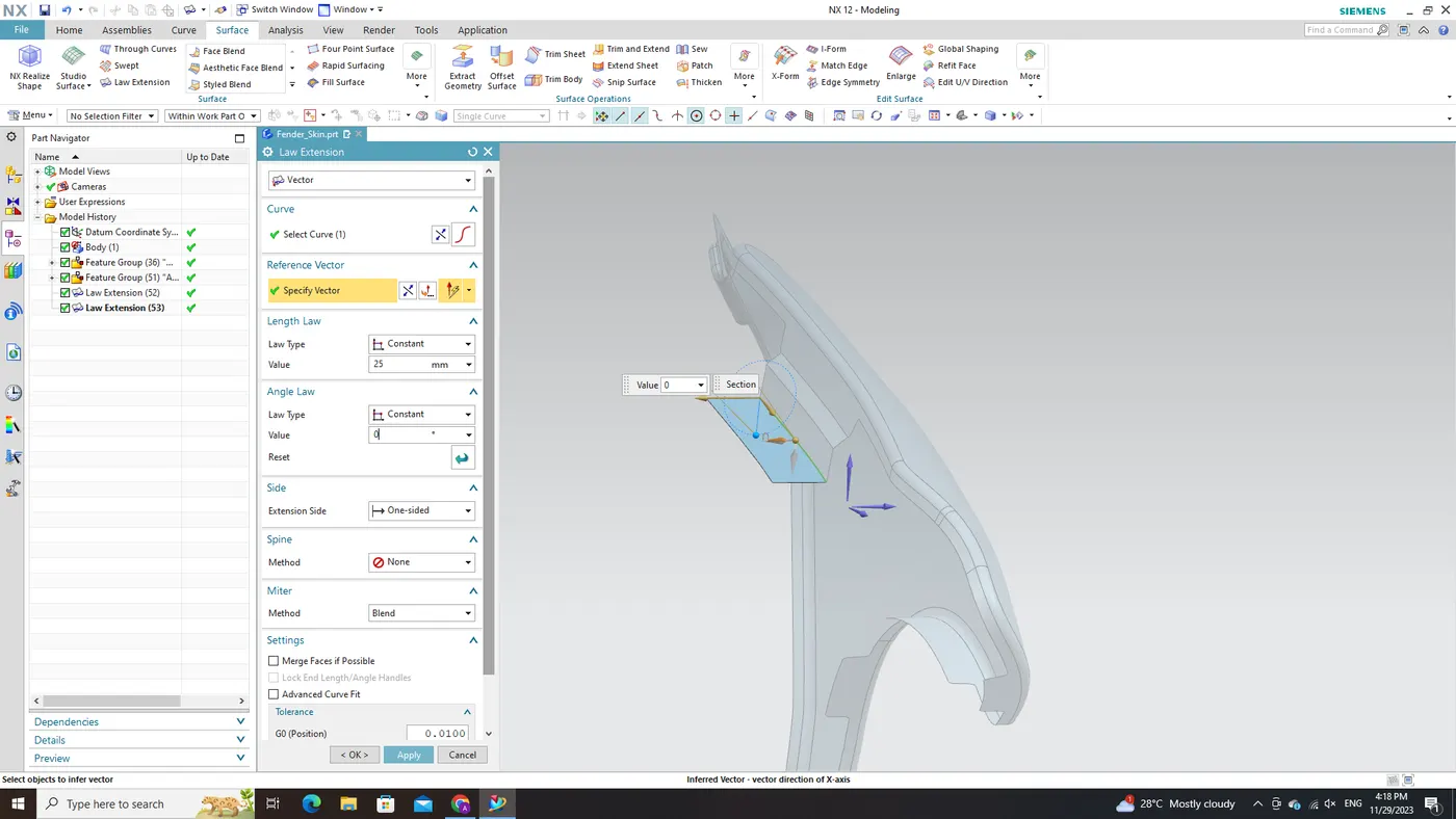
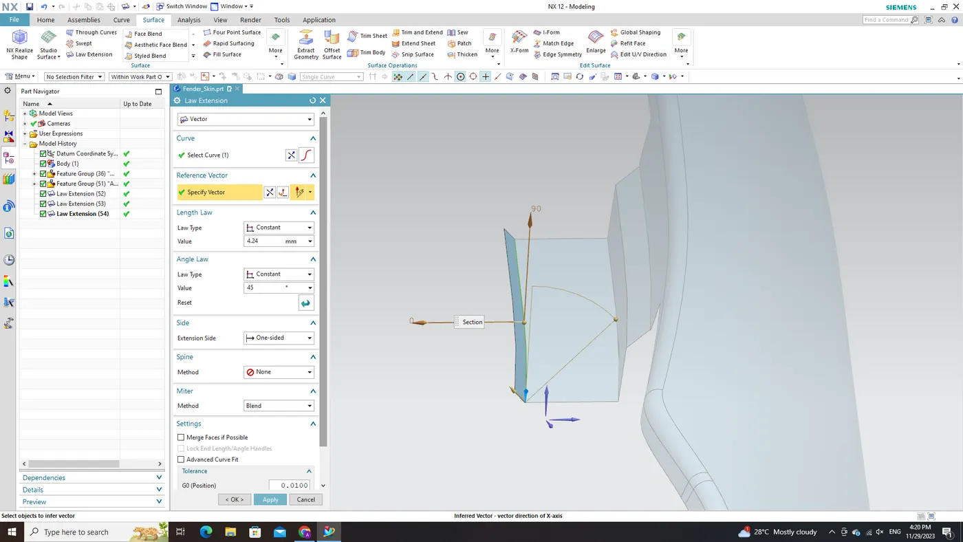
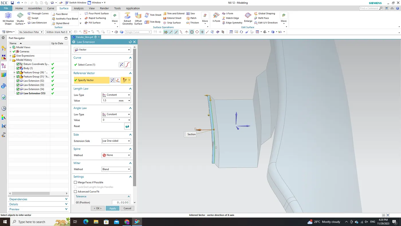
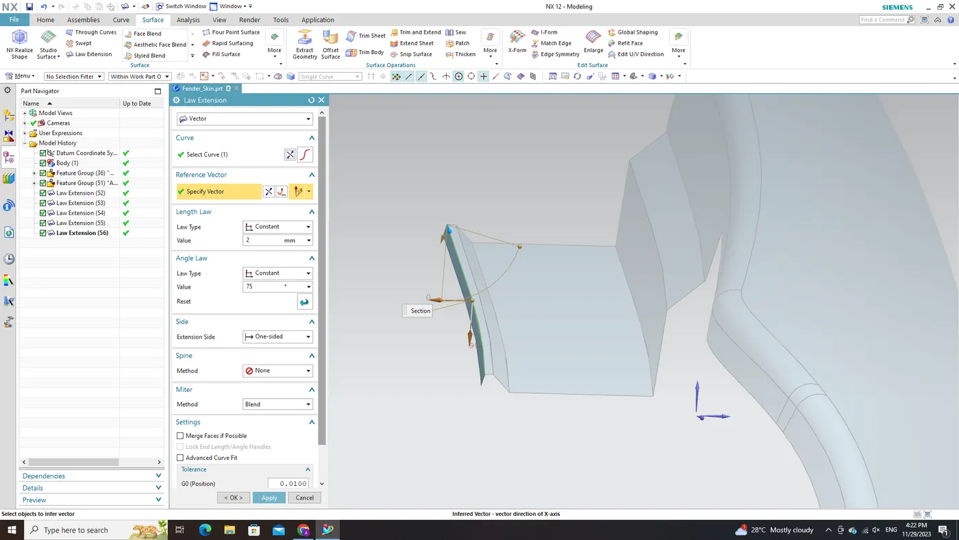
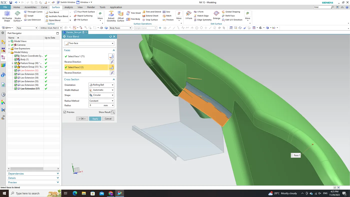
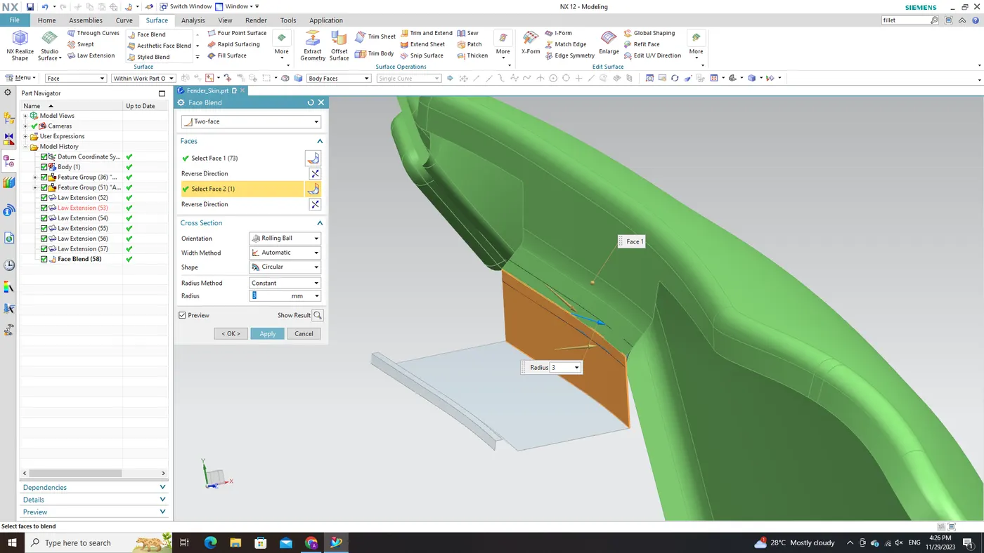
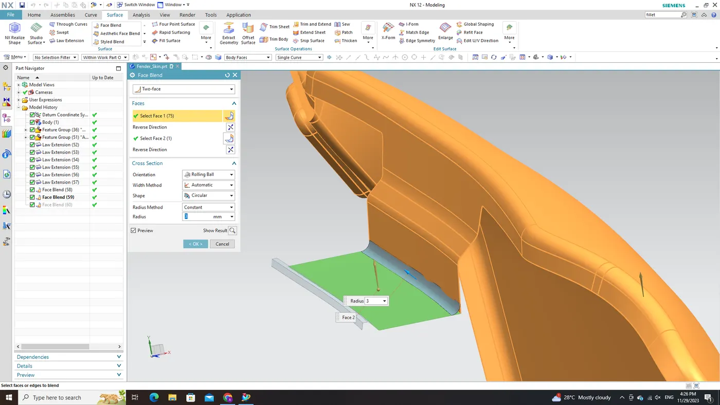
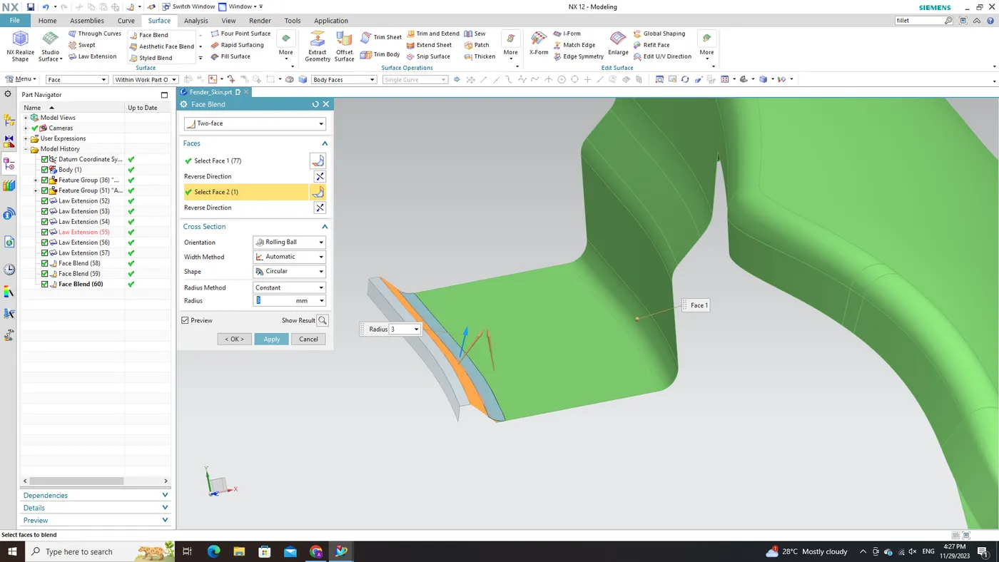
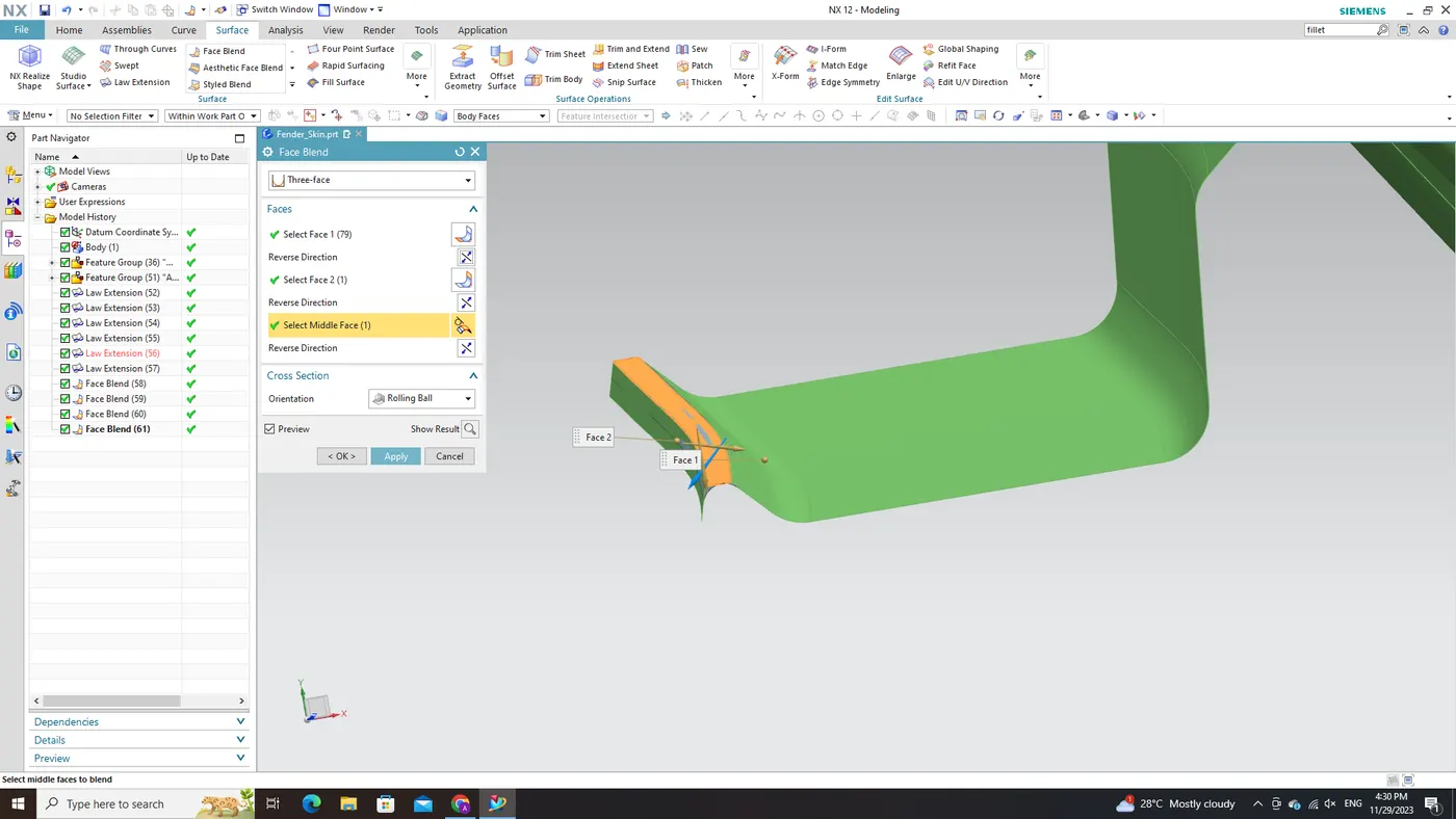
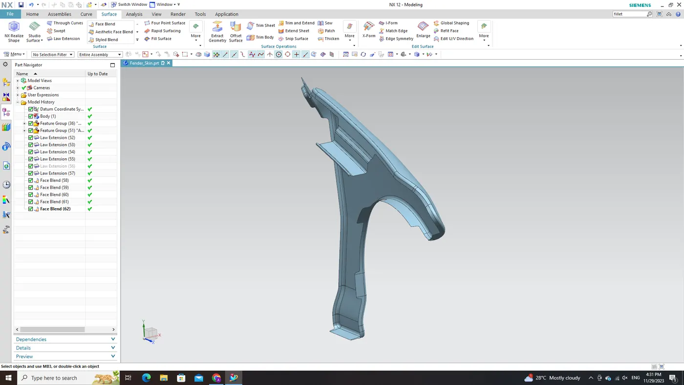
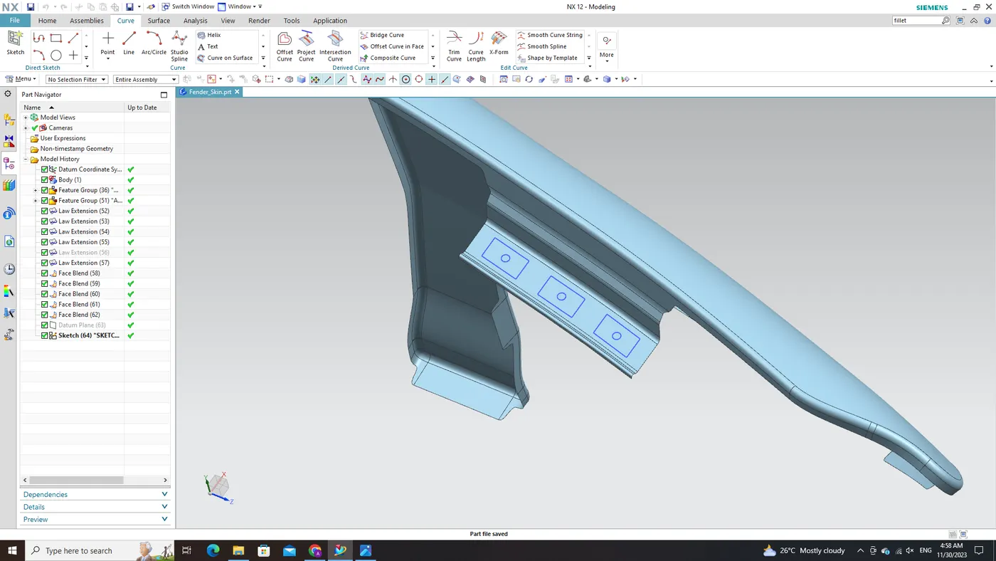
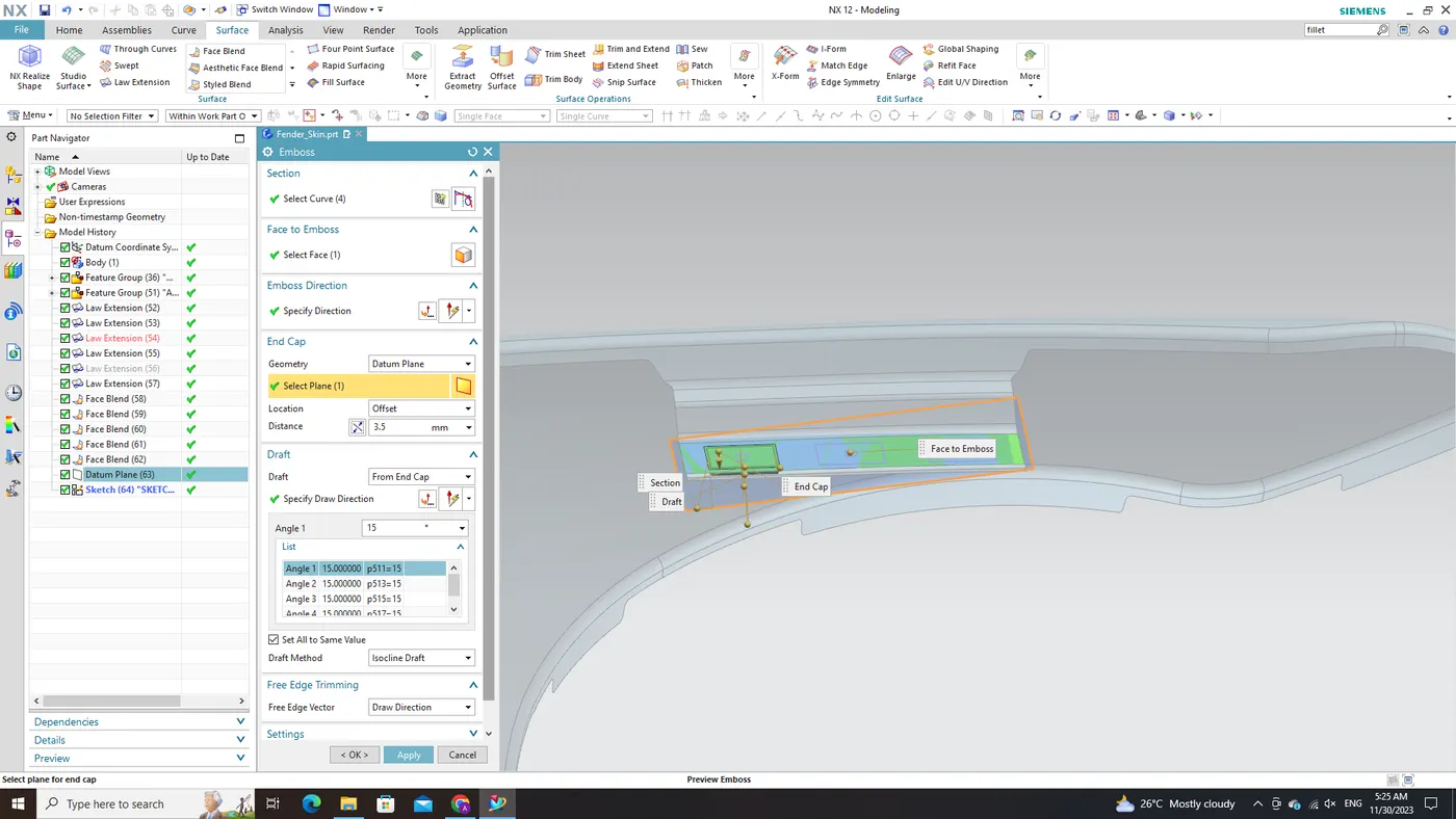
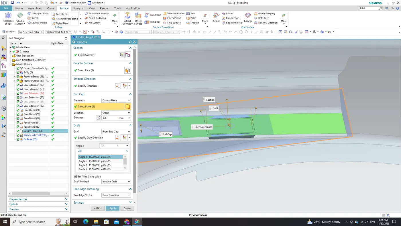
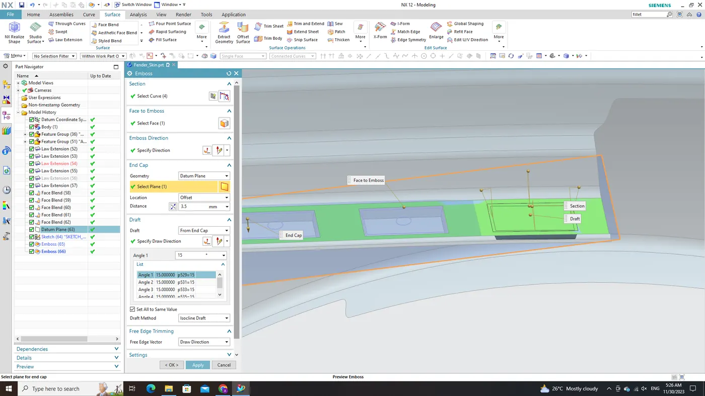
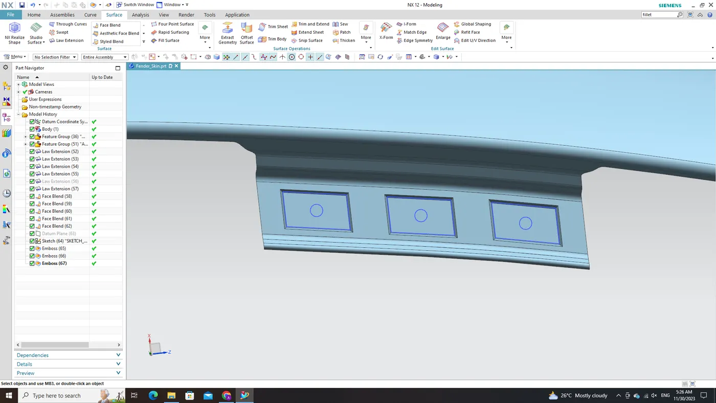
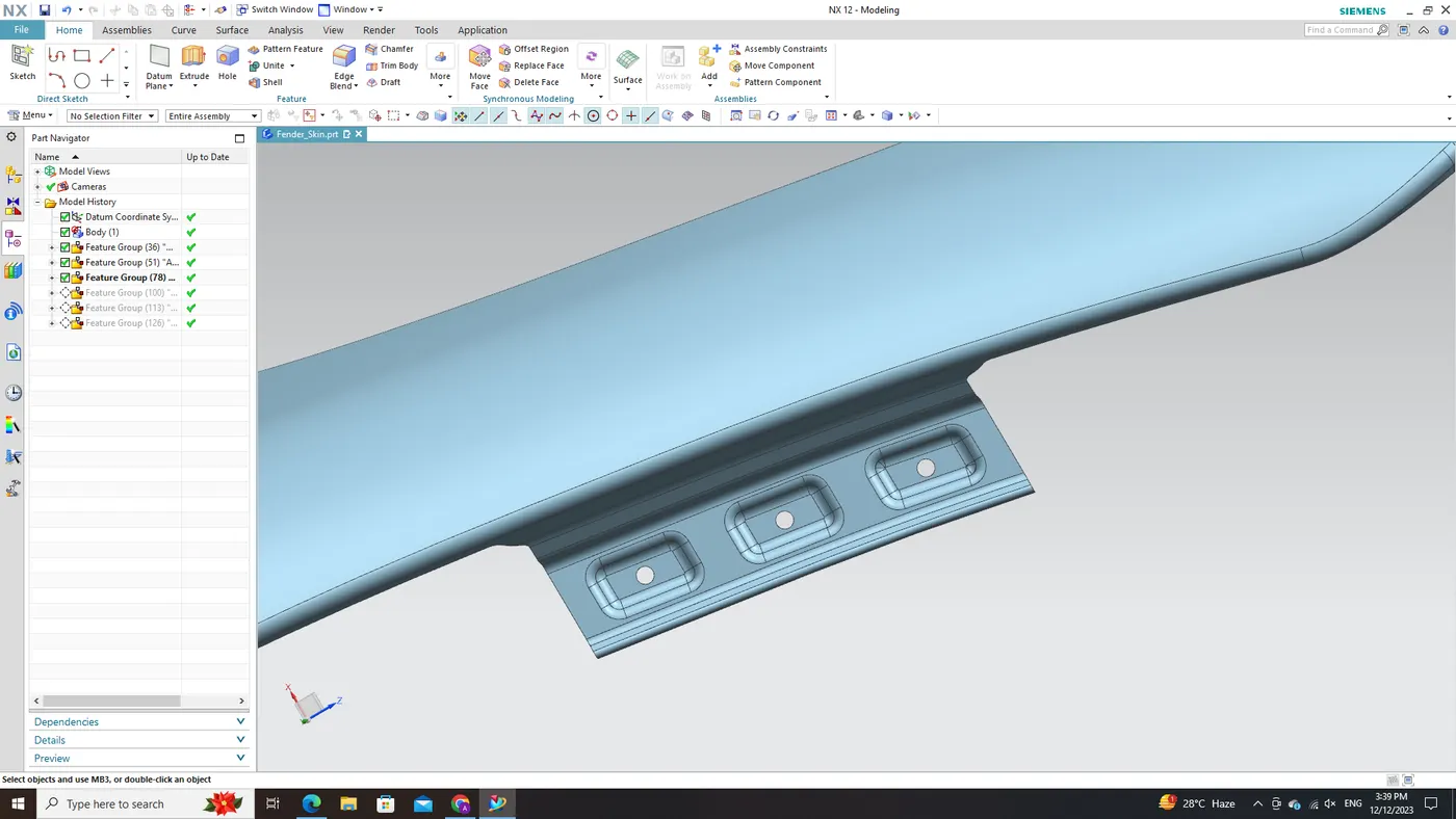
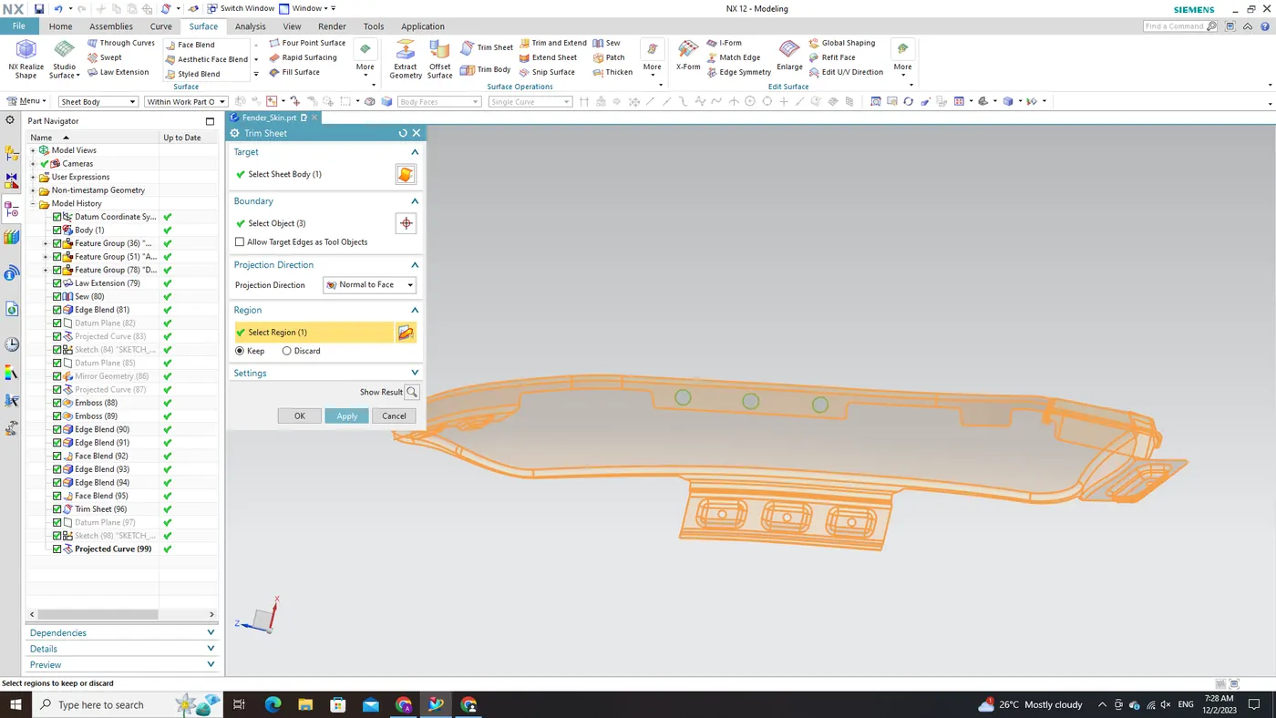
Following the successful creation of the Drip Area Mount for the fender, the subsequent task is to generate embossed holes for the fasteners that will secure this area to the main body near the engine compartment. This will be accomplished through the use of NX CAD's 'Emboss' command. Subsequently, holes will be created at the center of these embossed regions by projecting pre-defined hole sketches onto them.
- Employ NX CAD's 'Emboss' command to generate raised or depressed areas at specified locations within the Drip Area Mount. This command effectively replicates the desired embossed effect in accordance with design specifications.
- Employ sketches featuring pre-defined holes and project them onto the surface of each embossed region. Ensure precise alignment and orientation, considering both surface and hole positions.
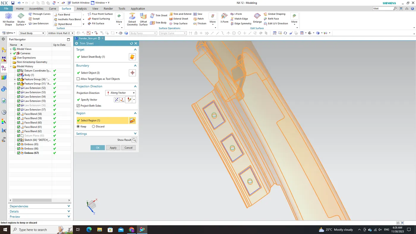
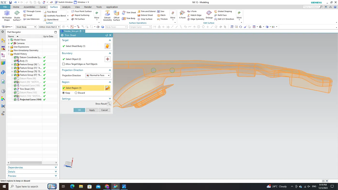
- To complete our design, employ NX CAD's 'Trim Sheet' command on each projected hole sketch within its corresponding embossed region. This process removes excess material from those areas, ensuring the precise placement and correct sizing of holes for fasteners. By systematically following these steps—creating embossed regions through 'Emboss,' projecting hole sketches onto those regions, and trimming surfaces with 'Trim Sheet'—we effectively integrate the necessary embossed holes into our Fender's drip area design with technical precision.
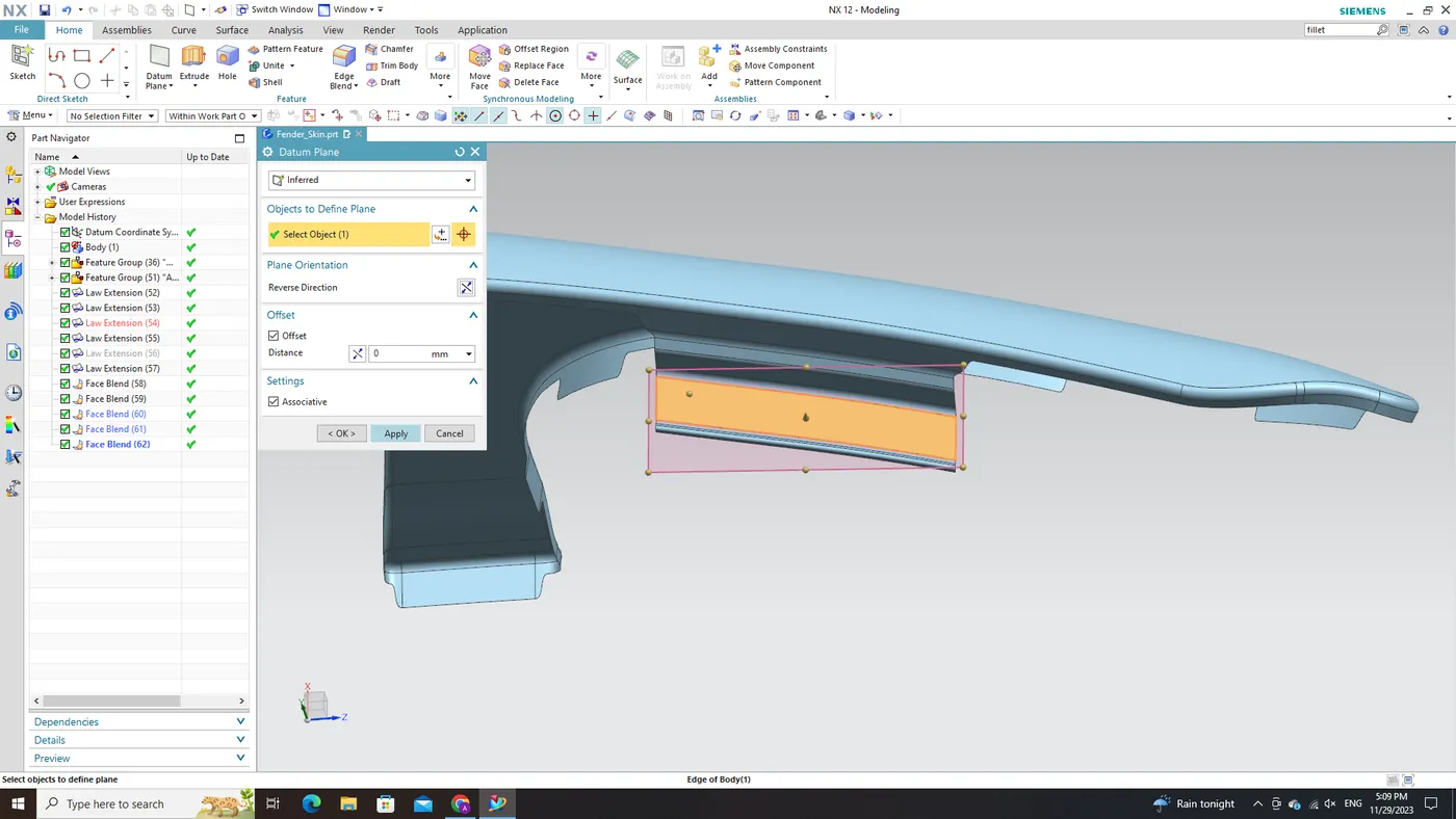
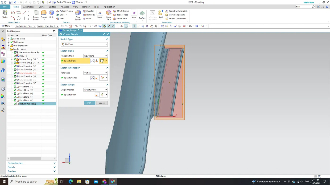
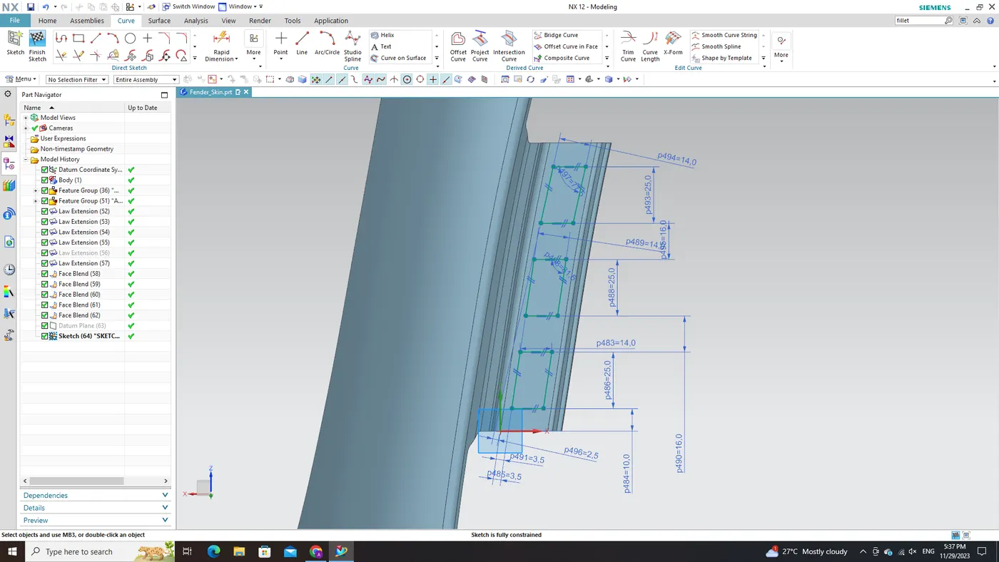
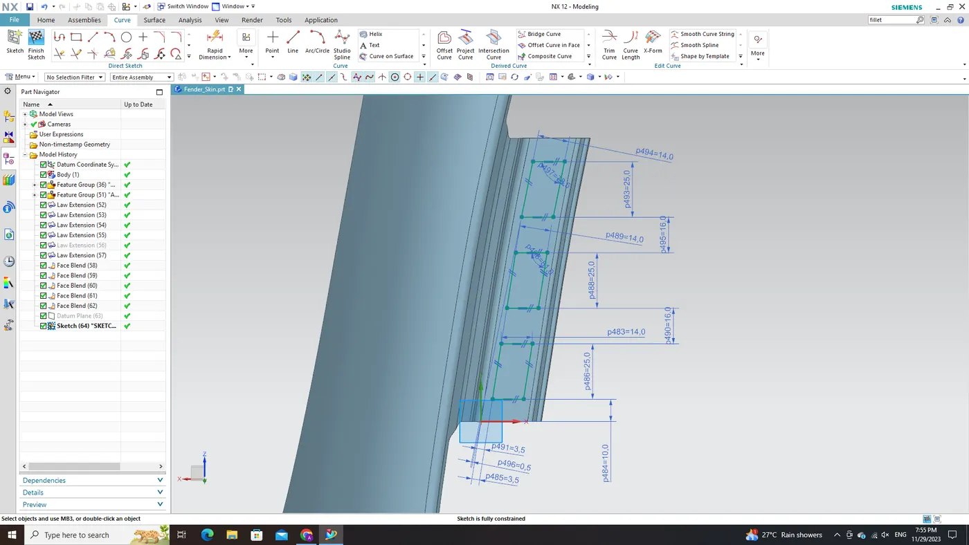
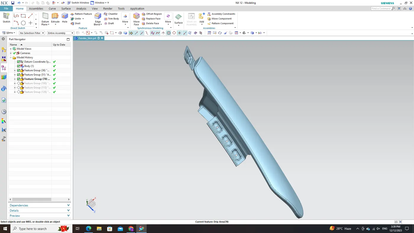
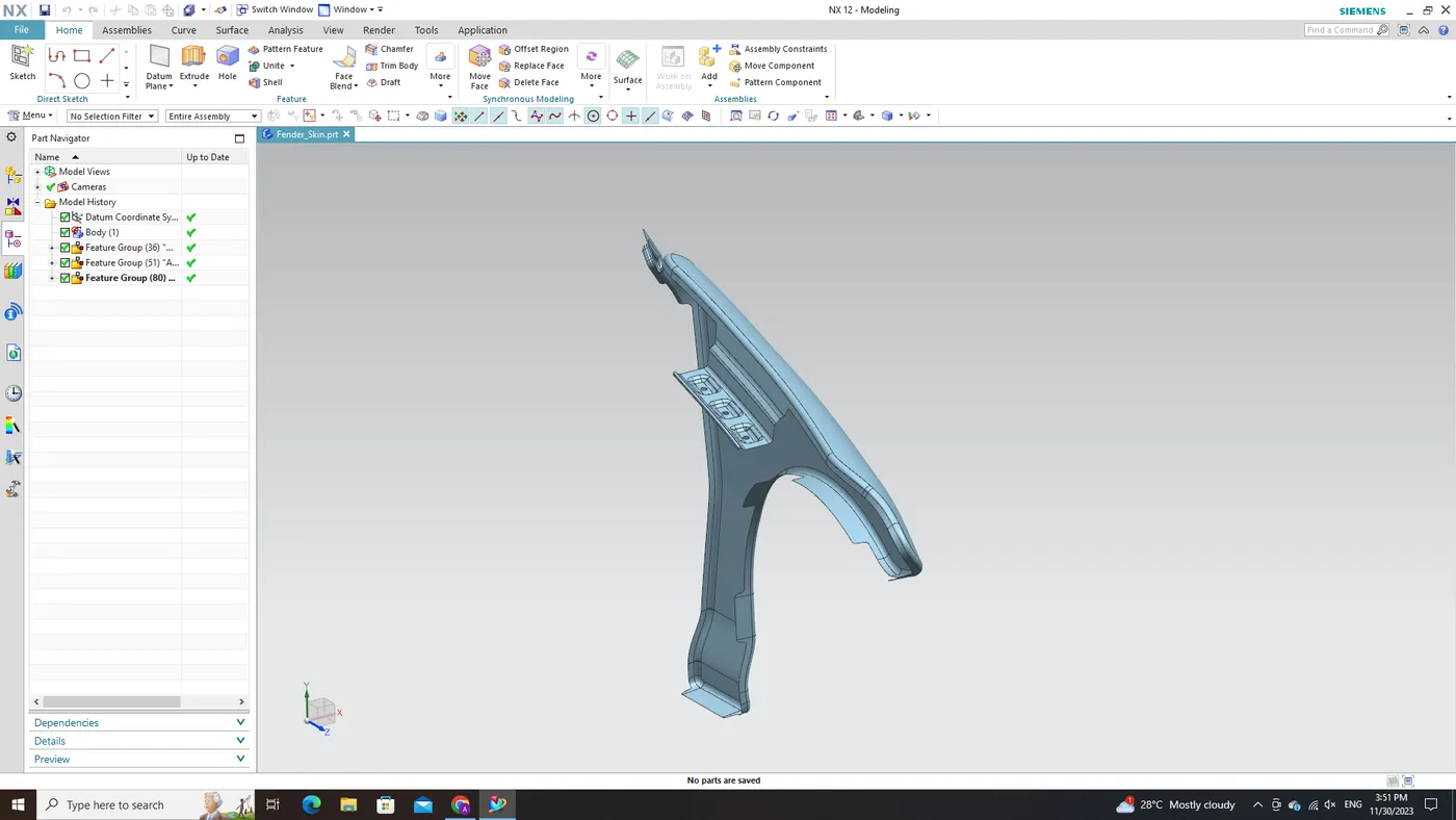
Bumper Mount Area:
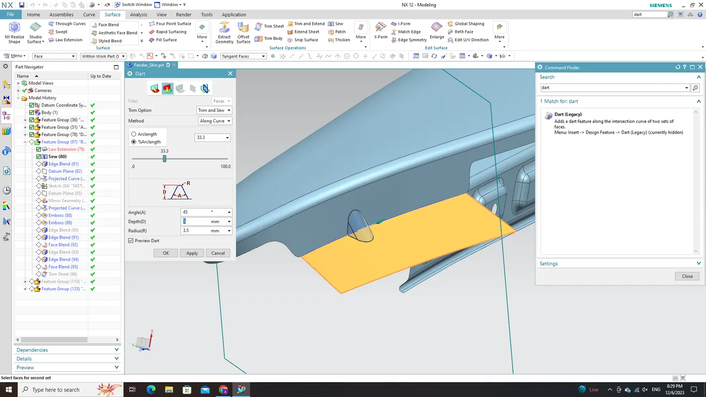
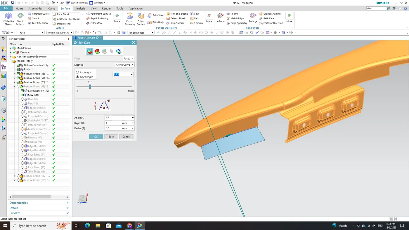
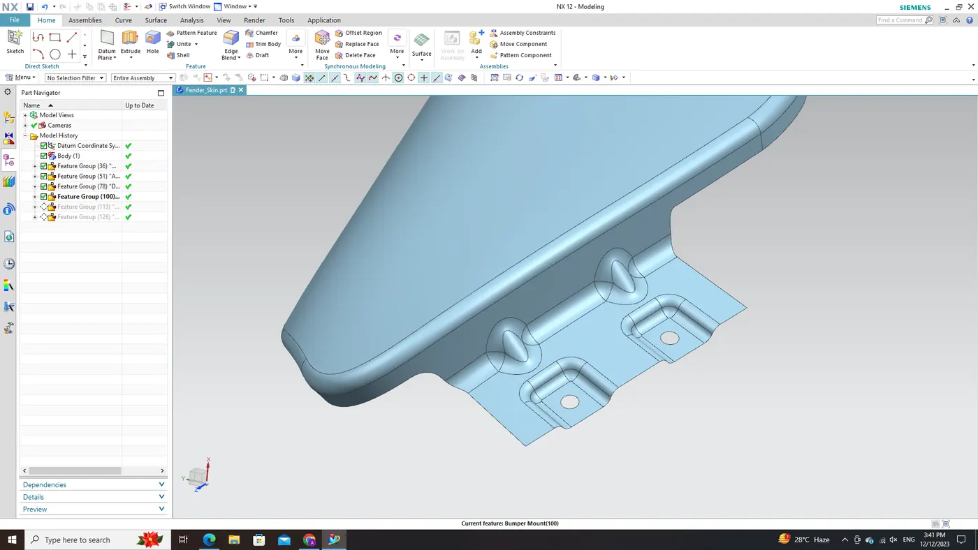
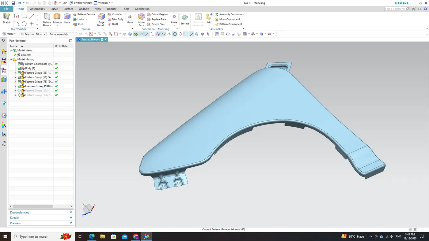
Having set up the A-Pillar and Drip Area mounts, the focus now shifts to crafting a dependable Bumper Mounting system. Leveraging NX CAD's robust toolset, we can meticulously design precise connection points between the fender and bumper structure. These connections necessitate careful engineering to guarantee secure attachment and provide protection against low-speed impacts. Extensive analysis of load paths, distribution, and crash energy management is conducted to optimize functionality and enhance safety within this crucial area.
Baffle/Splash Mount Area:
The designing of the fender mounting surface entails the creation of multiple mounts for the baffle area. In NX CAD software, diverse techniques, including the use of G1 continuity control, can be applied to ensure precise alignment for baffles responsible for controlling airflow, reducing turbulence, and enhancing acoustic performance. Optimizing these mountings contributes to improved aerodynamics, reduced noise levels, and overall enhancements in vehicle performance.

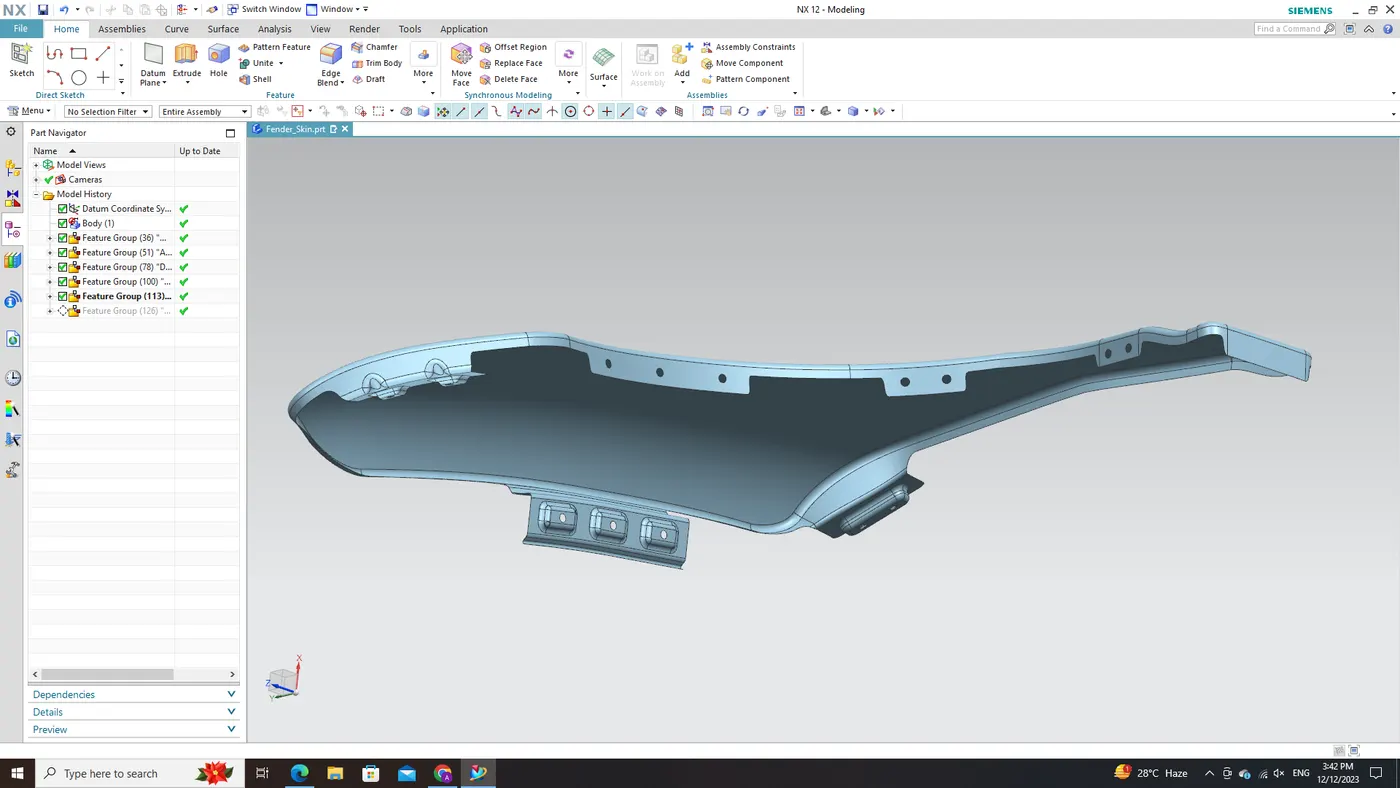
Sill Mount Area:
The last phase of designing the fender mounting surface entails the creation of Sill Mount Area. Strengthening the lower section of the fender necessitates a meticulously designed Sill Mount. This mount plays a critical role in improving stability and providing protection against potential ground-level hazards. In this phase within NX CAD software, the emphasis is on seamlessly integrating mounting points with rocker panels or side skirts. The objective is to establish robust connections capable of withstanding impact forces while harmonizing with surrounding design elements.
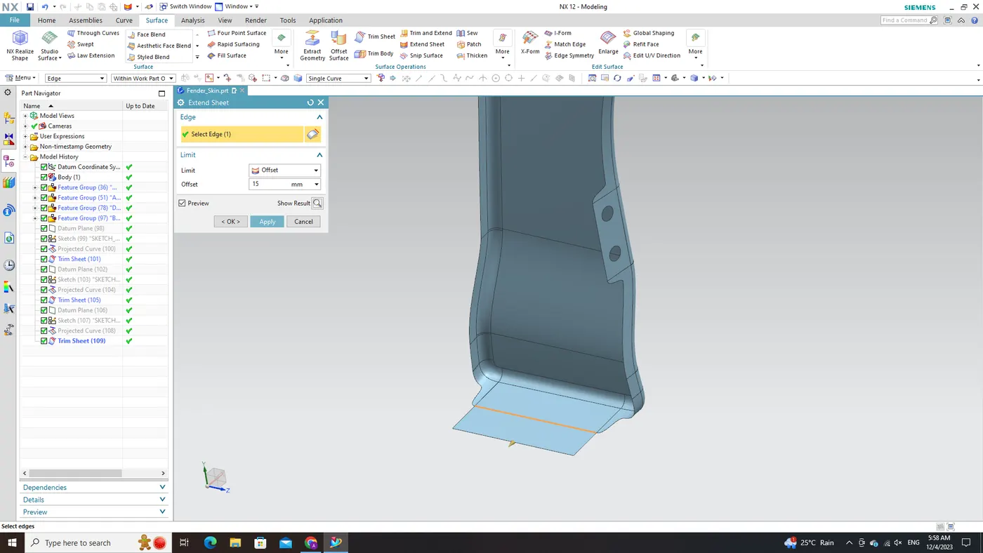
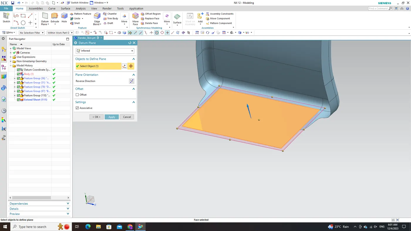
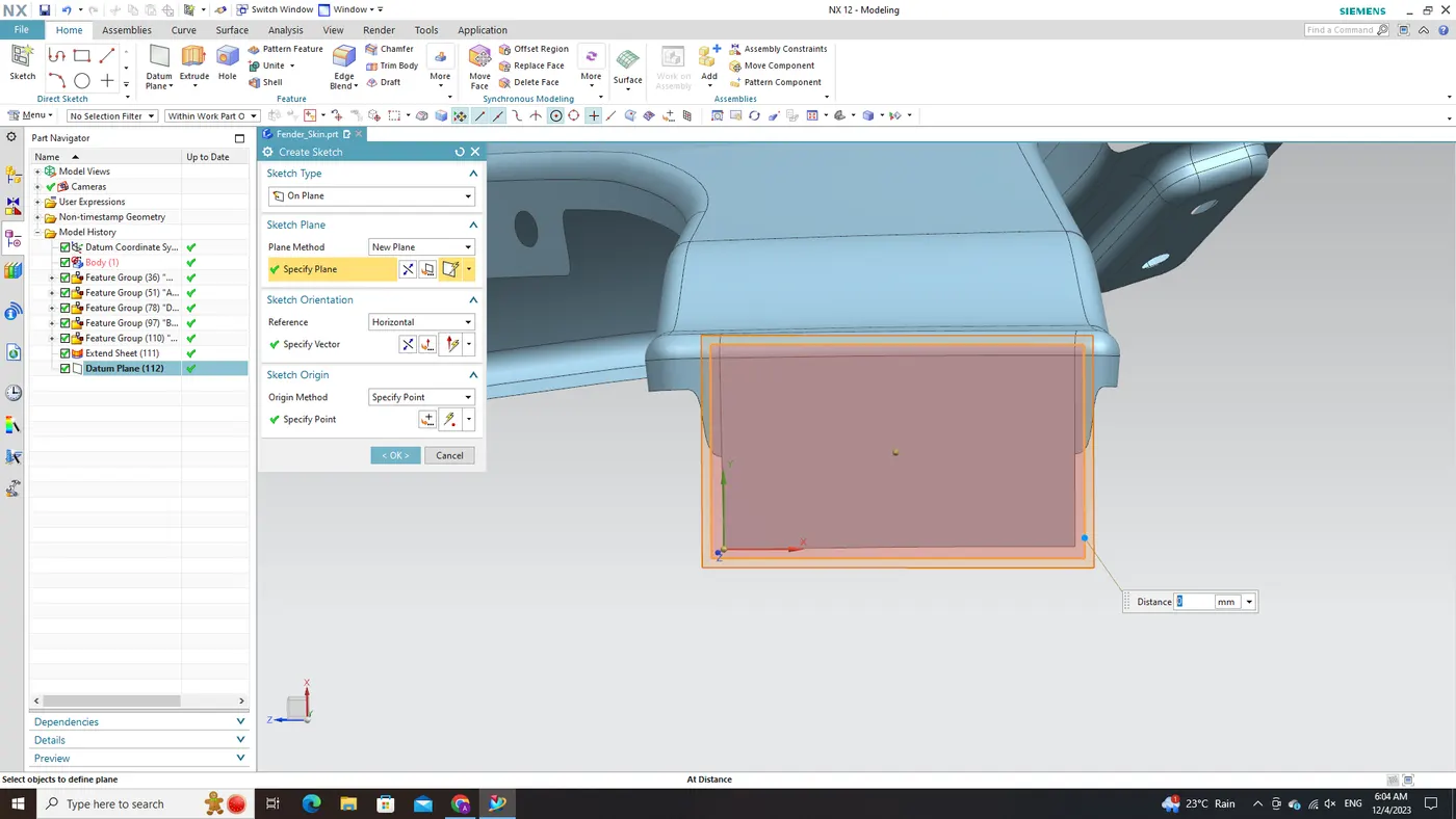
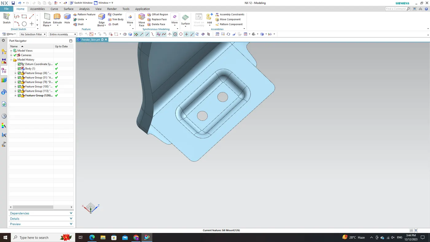
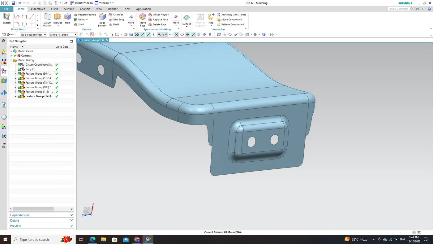
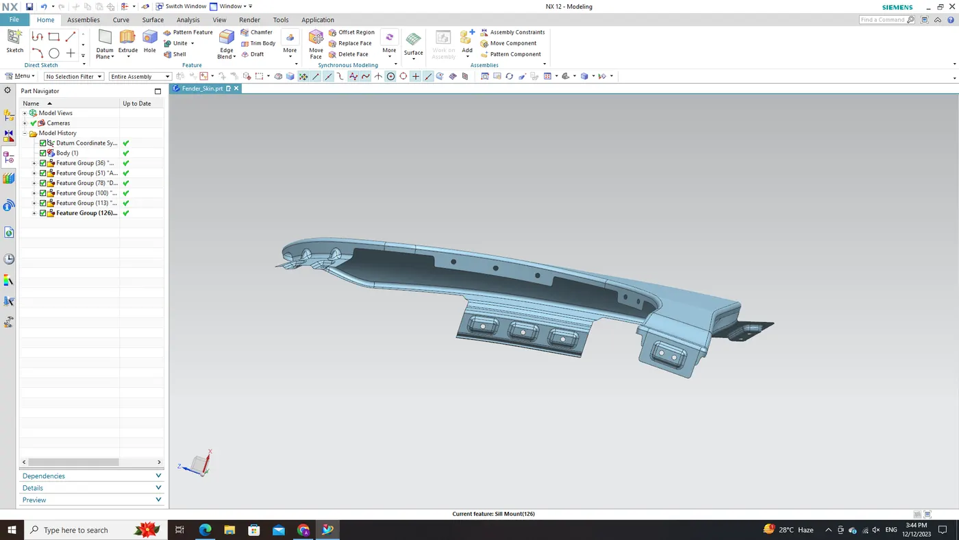
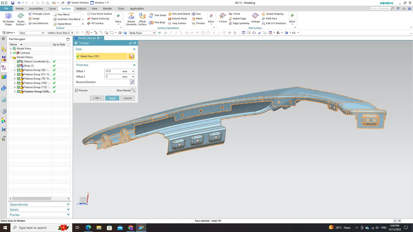
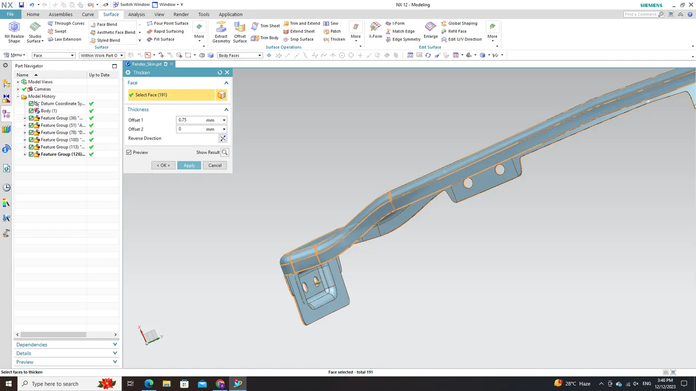
The concluding step in fender design involves uniformly thickening the entire surface, including all mounts, by 0.75mm towards the inward direction. This adjustment is essential to uphold the desired aesthetics of the fender while ensuring structural integrity and functionality. To accomplish this, we employed NX CAD software's 'Thicken' command. By specifying a thickness value of 0.75mm and selecting an inward direction, we precisely thickened the surface without compromising its overall shape and contours. Preserving the visual appeal of the fender was paramount, and we achieved this by avoiding any increase in thickness above the skin. This approach ensures that no undesirable changes are made to its external appearance.
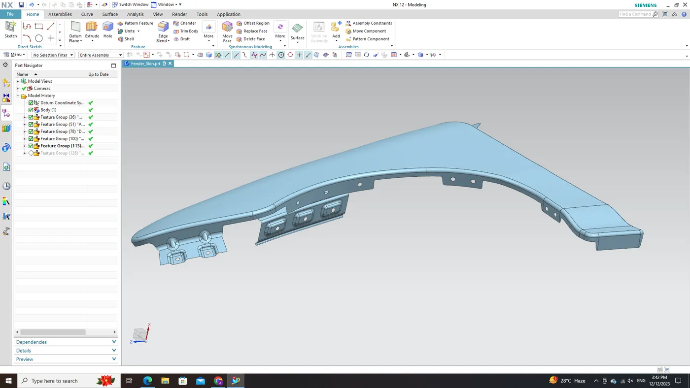
The resulting fender part seamlessly integrates all necessary mounts into its design while maintaining appropriate material strength and structural support. This process highlights how designers can leverage CAD software like NX CAD to create automotive components with precision and attention to detail. The ability to manipulate surfaces using features such as 'Thicken' allows for efficient design iterations while preserving aesthetic considerations.
In conclusion, by following these techniques and utilizing CAD software effectively, designers can strike a balance between functional requirements and visual appeal when creating complex automotive parts like fenders.
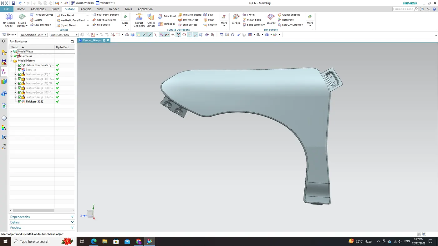
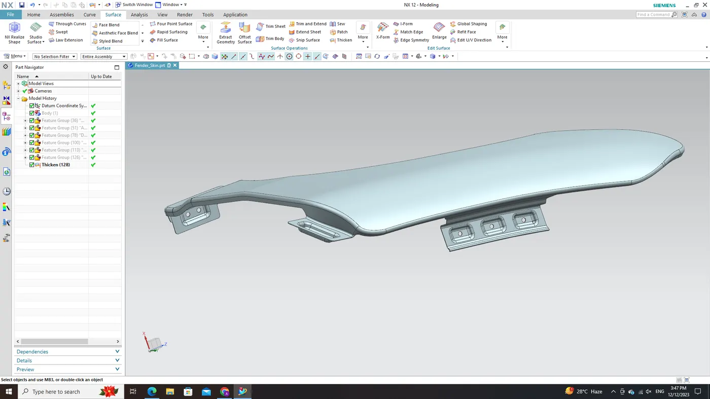
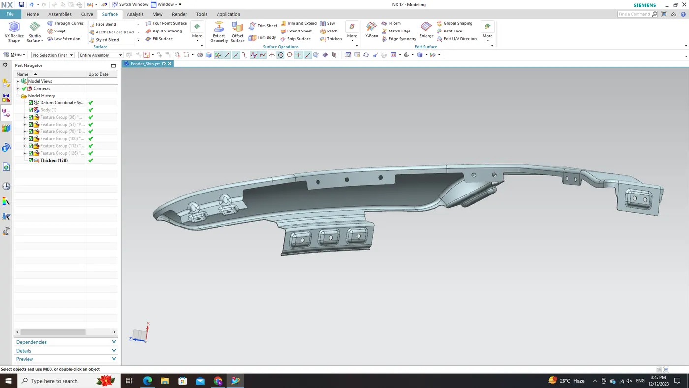
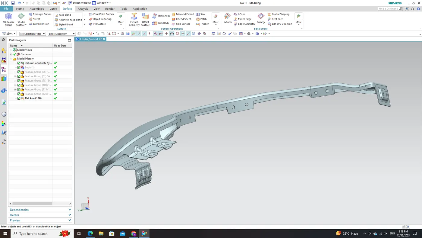
In conclusion, the design process for fender mounting surfaces within NX CAD software involves several critical steps that ensure precise connections, functionality, aesthetics, and structural integrity essential to automotive design. Thus, all mounting areas for the car front fender which is designed from given skin data and also consider the master section is done by following all design rules.