Project 1
Statement of assignment:
Route the Wiring harness on Given Engine and Prepare flatten view drawing in CATIA V5. Application of all Packaging rules, Industry best practices studied in this course shall be demonstrated in design. Apply Protection coverings as required.
Available connector 3D data can be used, or you can download the connectors from www.te.com
Prepare & Submit all necessary reports like clearance, Clipping/Clamping selection, Harness fixing requirements, Harness continuity, Assumptions if any along with CATIA 3D data.
Objective:
The objective of the project is to route the wiring harness on given Bugatti V16 Engine and prepare flatten view drawing in CATIA V5. All types of packaging rules have to be considered while routing the harness. Also, industry best practices should be demonstrated in design. All the necessary details like clearance, clipping/clamping selection, harness fixing requirements, harness continuity should be provided in order to design wiring harness.
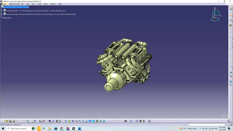
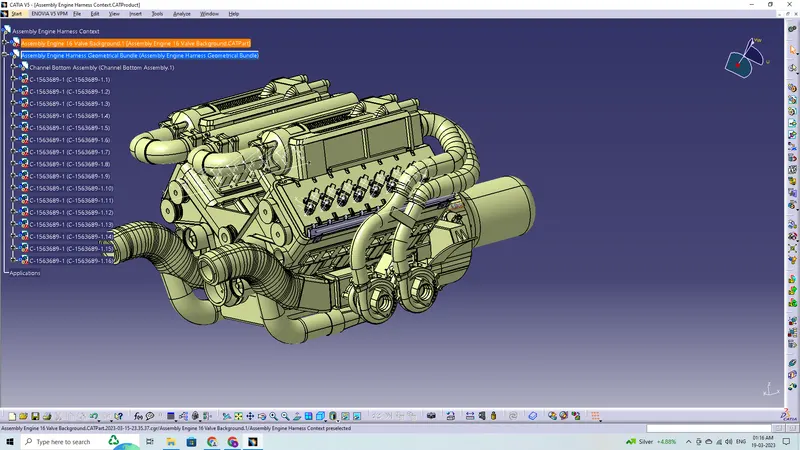
- The above figure shows the 16 valve Bugatti Engine where 8 cylinders are placed on the right side and 8 cylinders are placed on the left side.
- Generally, 4-pole connectors are used for fuel injectors of the engine.
- There are total 16 injectors where 8 injectors are used for 8 cylinders on right side and 8 injectors are used for another 8 cylinders on left side.
- The engine will also have an interconnection connector which will connect the engine to other parts of the vehicle. We will be using a 12-pole electrical connector with a mounting clip feature as an interconnection connector.
- Also there are 3 cam-shaft sensors, so there are total 24 connectors that we have to connect electrically.
- The plastic guiding channel used in this harness should bemade of a material that can withstand at least 150 degree Celcius.
- The bend ratio for the all bundle segmets should be 1.4
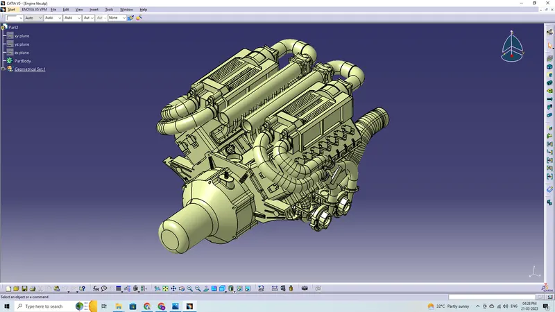
Parts used in Engine Routing:
Connectors:
The given components are as follows:
- C-173090-2-A-3D
- C-282080-1-D-3D
- C-776438-4-D-3D
- C-1563689-1-B-3D
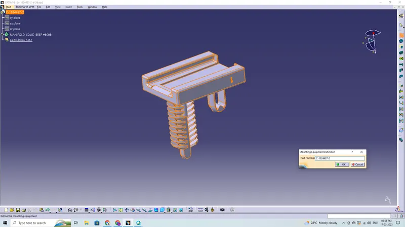
- C-1924487-2-D-3D
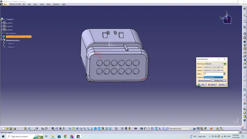
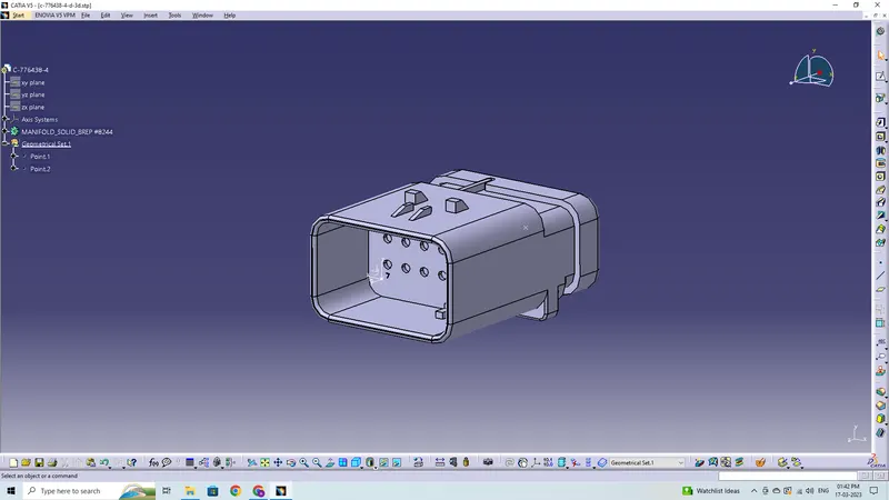
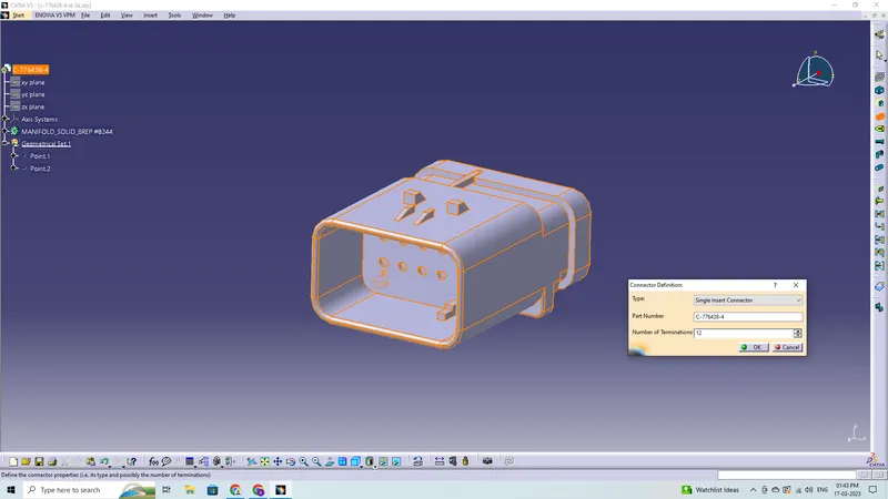
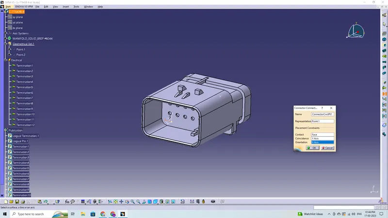
C-776438-4-D-3D
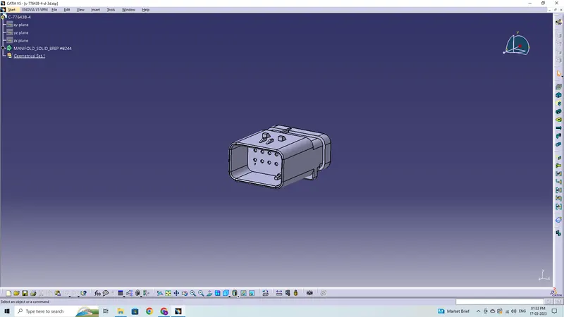
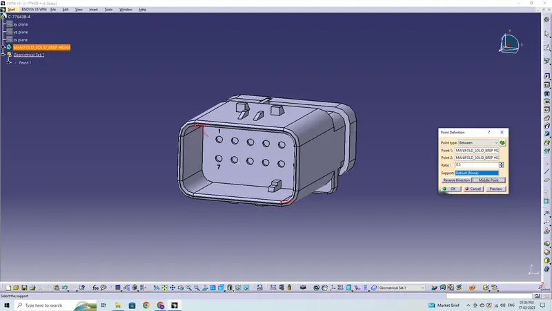
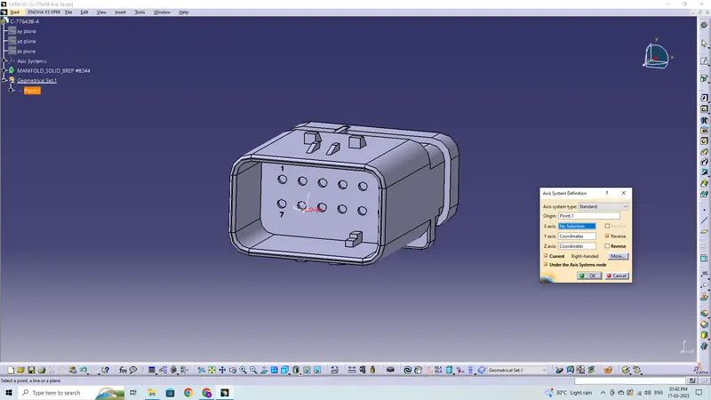
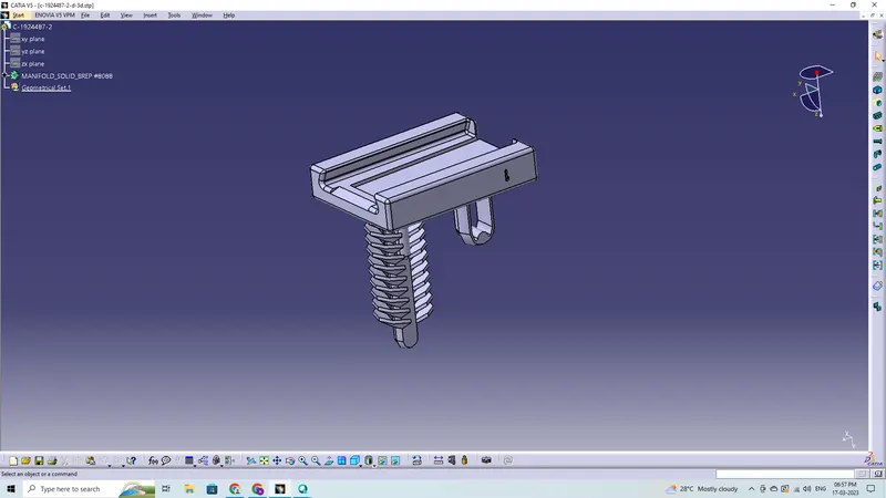
C-1924487-2
C-173090-2
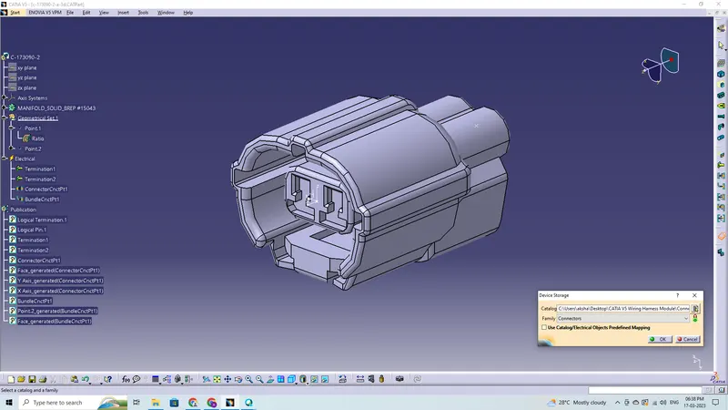
C-282080-1
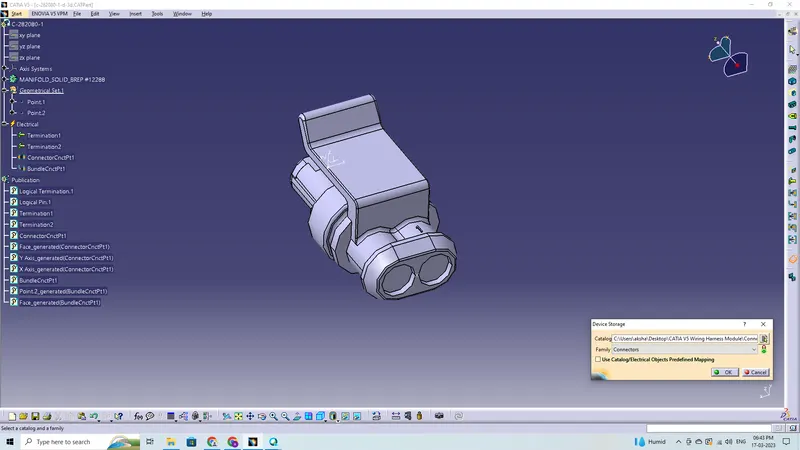
C-1563689-1
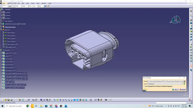
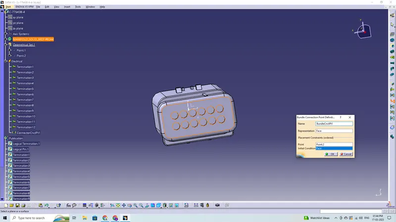
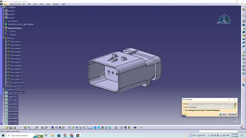
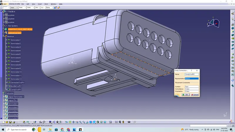
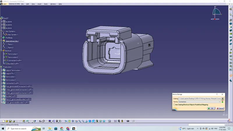
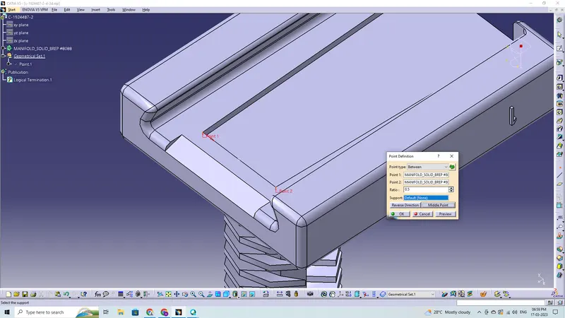
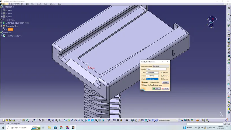
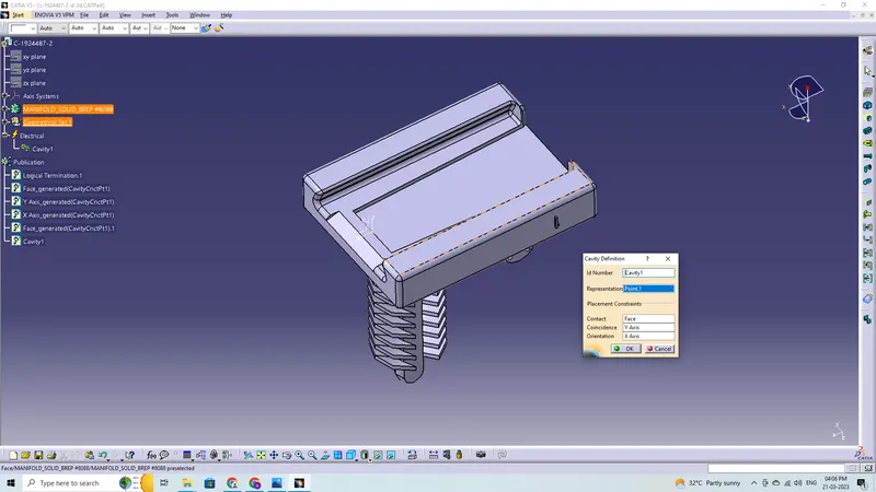
These are the steps required to do in this project for connector definition-
- Create the required geometrical parameters for connector
- Create a bundle entry point
- If connector accommodates clip then define a geometrical parameter for the clip
- Define part as a connector or mounting equipment
- Create bundle connection point
- Create a connector connection point
- Create a cavity connection point if there is a clip
Clips and Clamps (Support Components):
The given components are as follows:
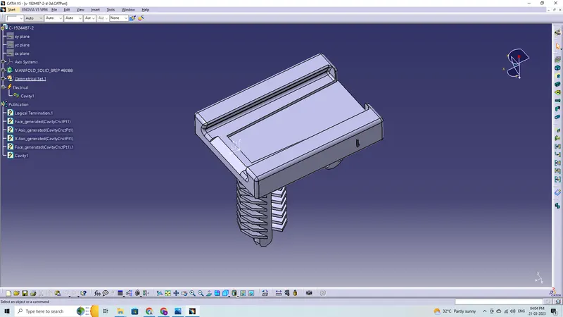
- Connector Clip
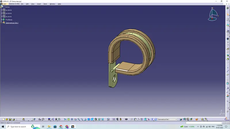
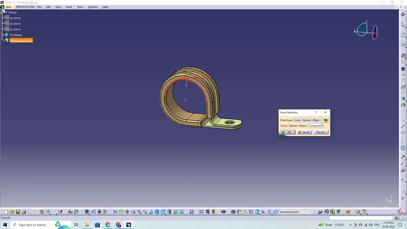
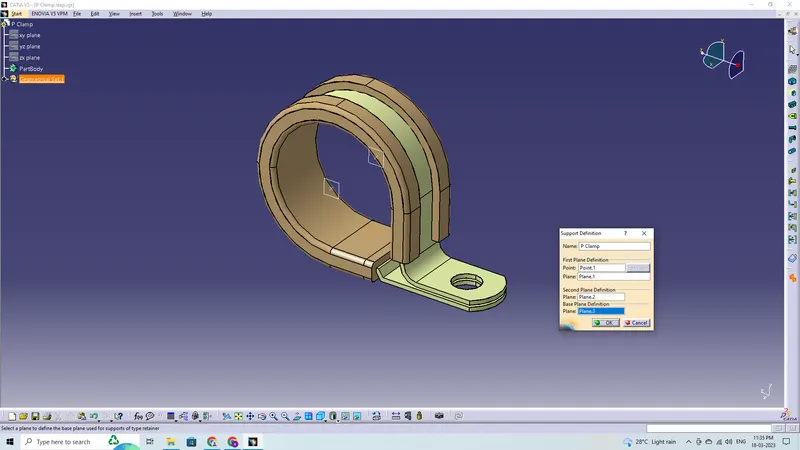
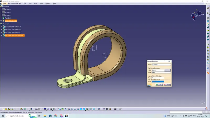
- P-Clamp
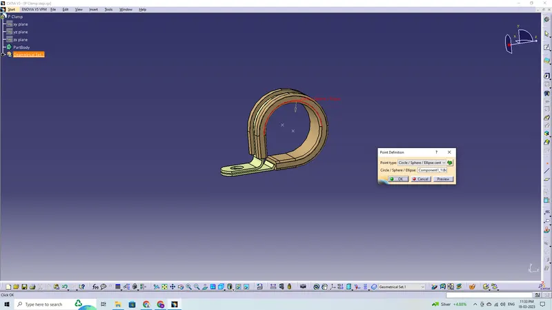
- Fir Tree Clip
Connector Clip
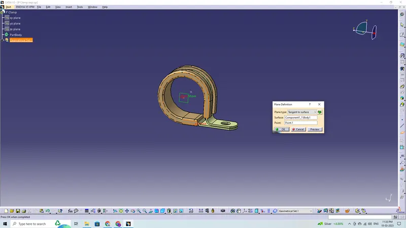
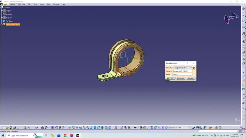
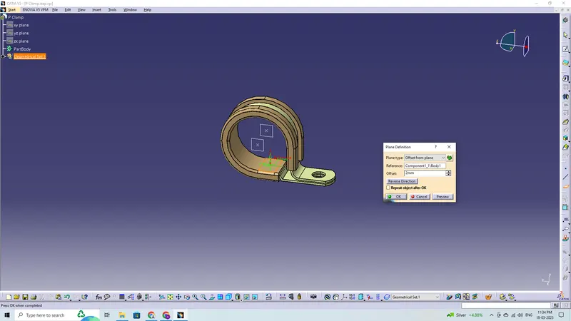
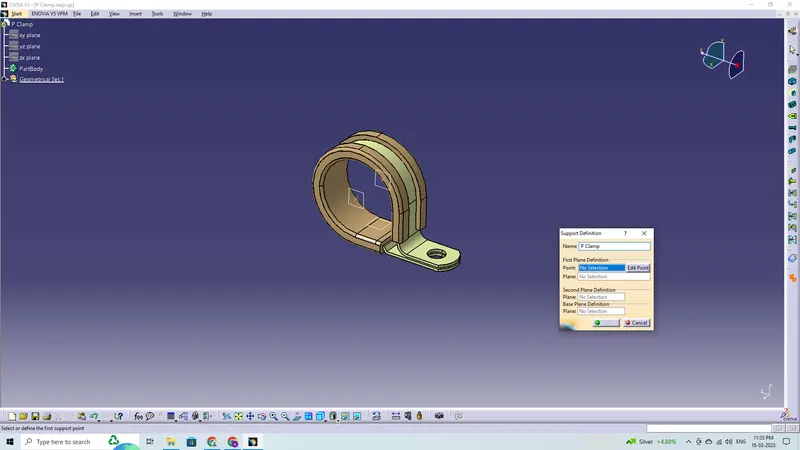
P-Clamp
Fir Tree Clip
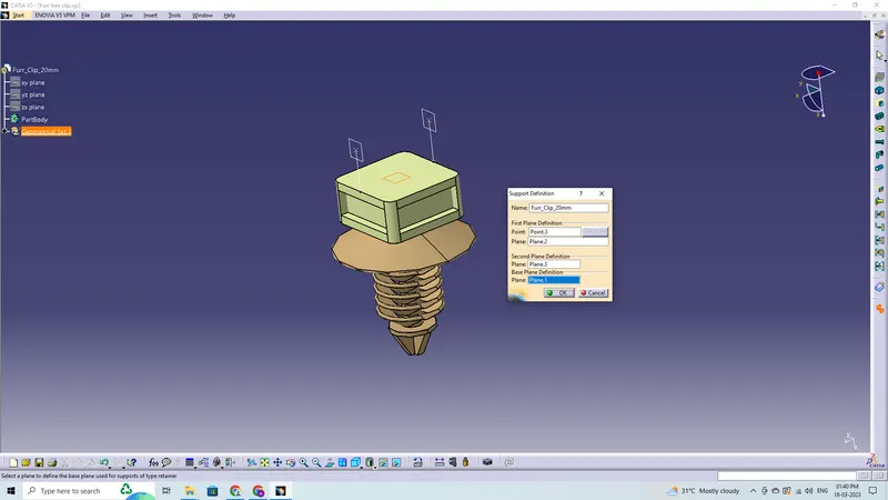
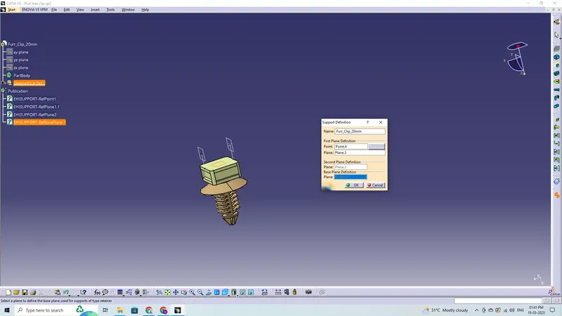
These are the steps required to do in this project for clips and clamps definition-
- Create the required geometrical parameters for the part
- Create entry point and entry plane
- Create exit plane and base plane
- Define part as electrical support
Plastic Guiding Channel:
The given components are as follows:
- Channel_Bottom_Left
- Channel_Bottom_Right
- Channel_Top
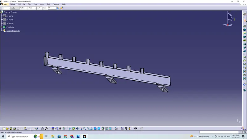
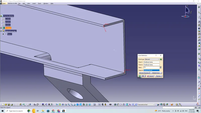
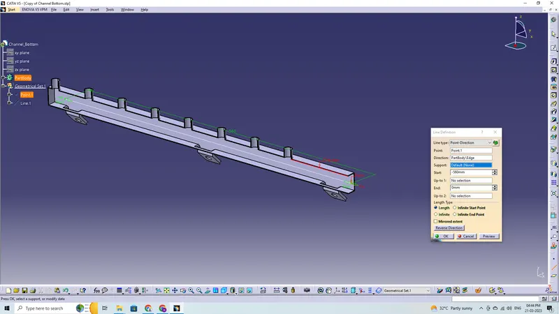
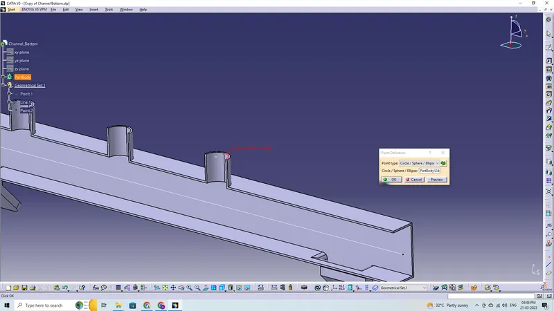
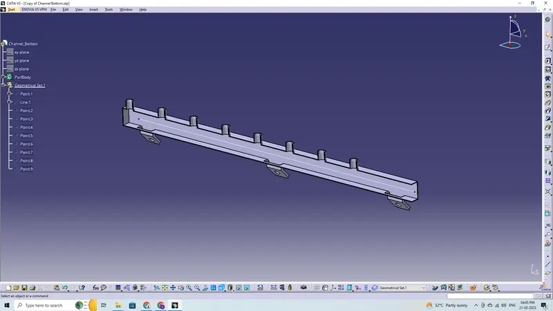
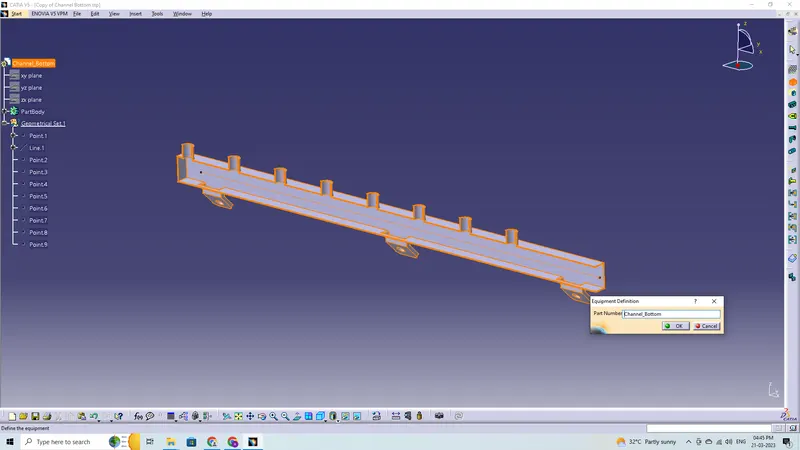
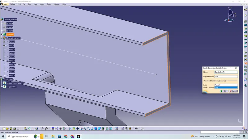
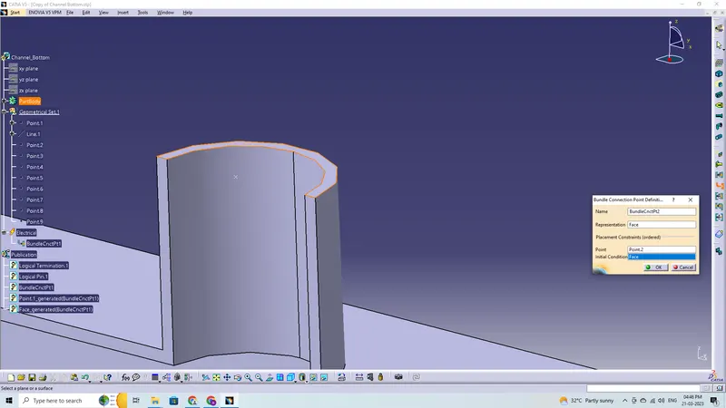
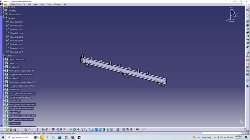
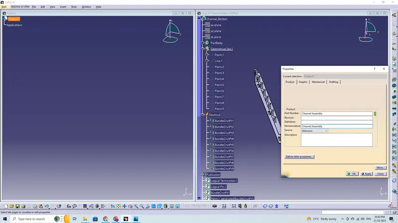
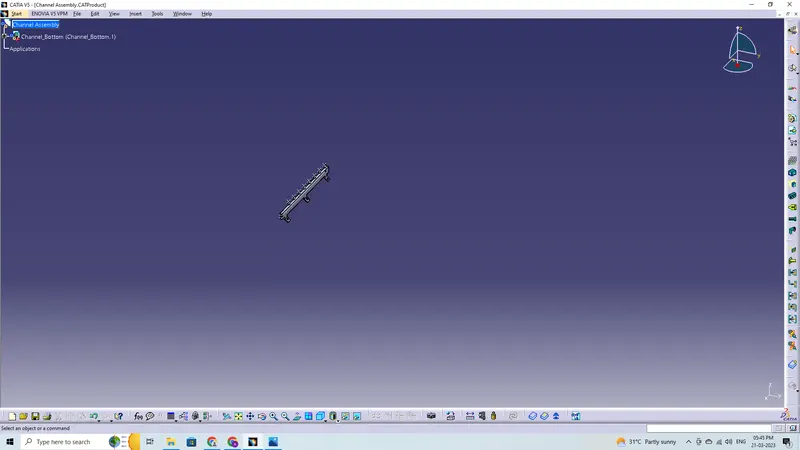
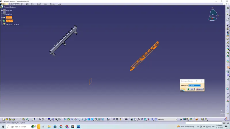
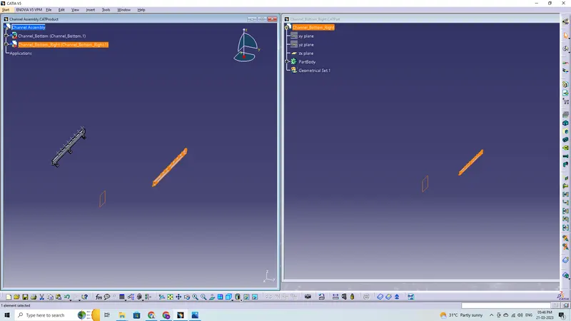
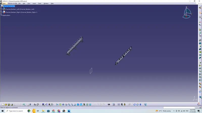
These are the steps required to do in this project for connector definition-
- Create the required geometrical parameters for channel
- Create a bundle entry point and exit point
- Create a line curve between the main entry and exit points for creating the multi-branchable using external curve inside the channel
- Create 8 bundle entry points on the openings for connecting the injector connectors
- Define part as a mounting equipment
- Create define bundle entry points using the define bundle connection point
- Create a symmetry for both channel bottom and top using symmetry and repeat the given steps.
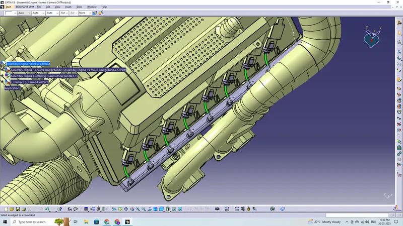
Because the 8 injectors on the right side and the 8 injectors on the left side of the V16 engine are so close to one another, we must now build a plastic guiding channel. So, the ideal option for proper and simple wiring harness routing is plastic guiding channel. The complicated wiring harness routing will be lessened. On the right and left sides of the engine, we will need two different guiding channels. Now that we have defined the geometrical specifications of the guiding channel, we can place it.
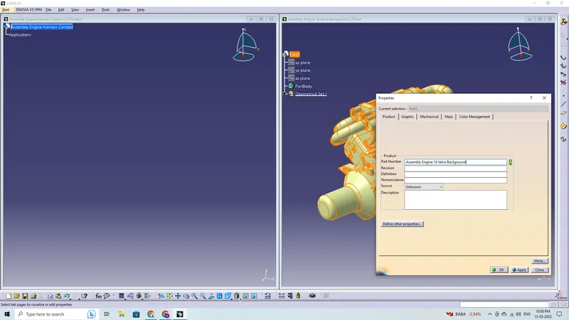
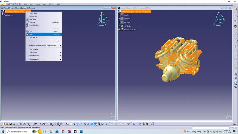
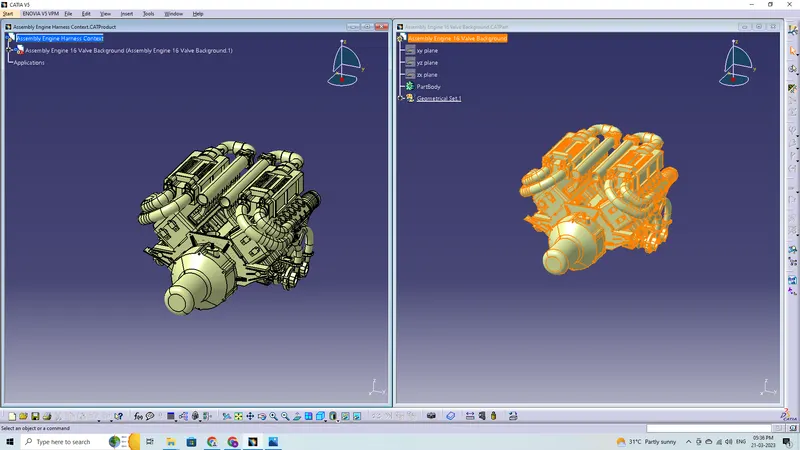
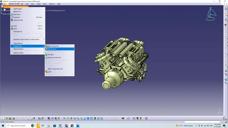
Context Assembly with Geometrical Bundle
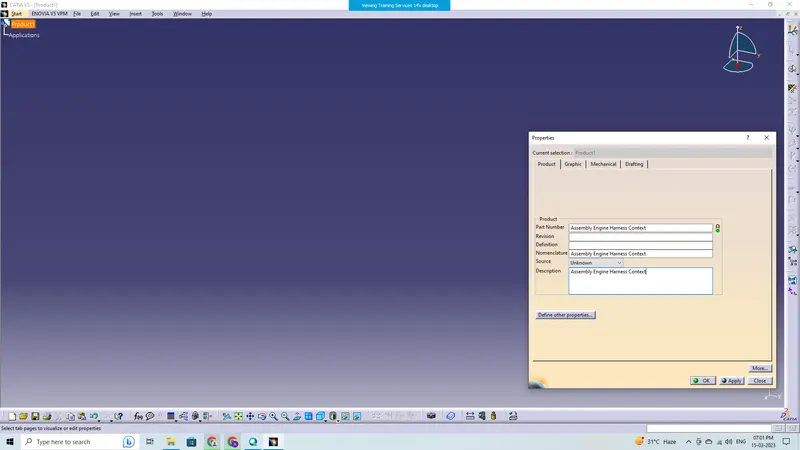
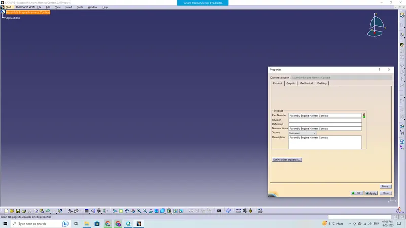
Context assembly is nothing more than the product file including the geometric bundle for the engine harness and the engine 3D-CAD data. All of the connectors, additional mounting tools, clips, and clamps that are electrically defined for the assembly are included in this geometrical bundle offering. L-clamps made of sheet metal are installed during the main context construction. Then we must go to the electrical harness assembly workbench, and before adding any parts, the Geometrical bundle product file needs to be electrically configured using the Define Geometrical bundle option.
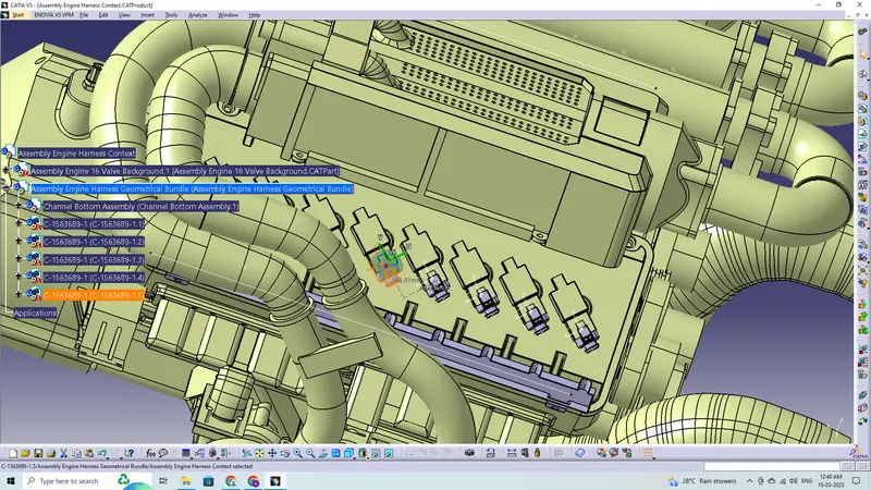
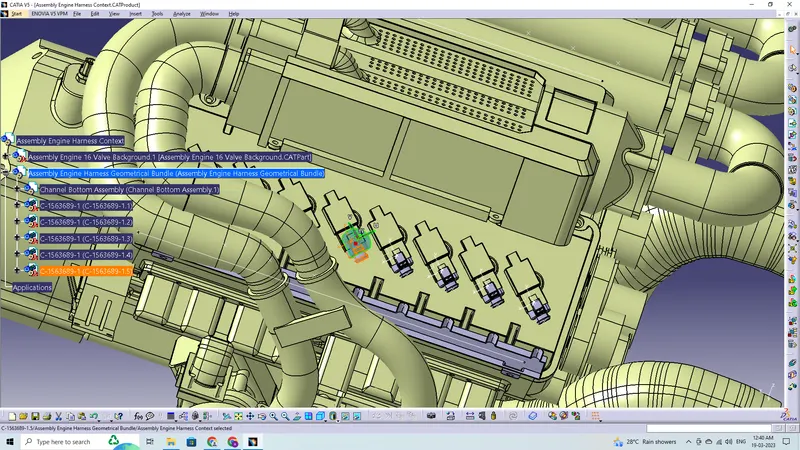
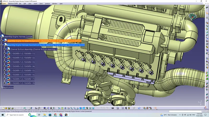
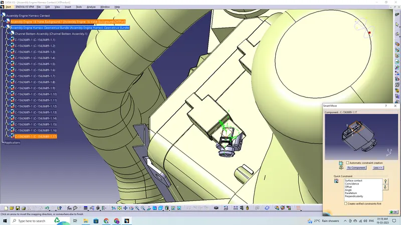
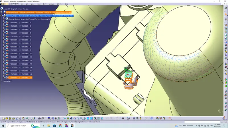
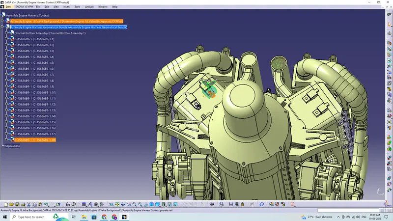
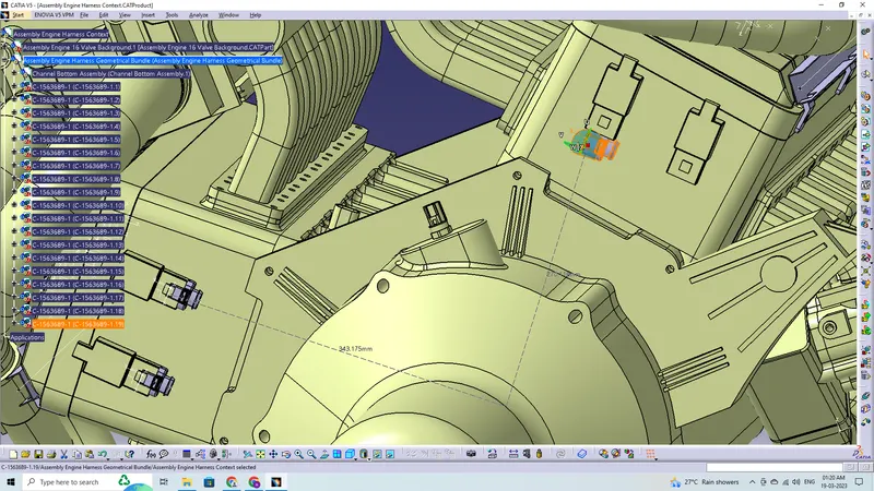
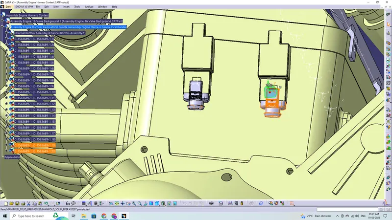
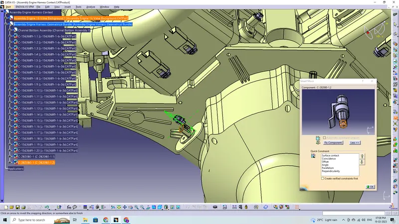
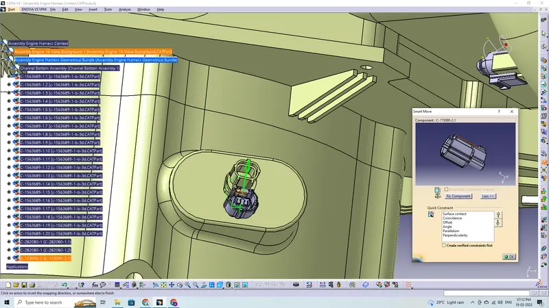
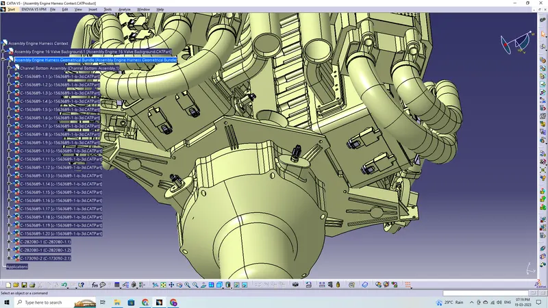
Adding 4 pole connectors to all fuel injector sensors. Connectors can be added again by copy pasting the 1st imported connector. Place the connectors on all the fuel injector sensors and cam-shaft sensors using the manipulation tools like move, smart move, snap tool and also using the compass. Adding all the other connectors for sensors like coolant heat sensor, neutral position sensor, speed sensors. etc according to their respective places.

Placing the Interconnection Connector and L-Clamp Support
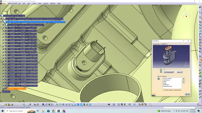
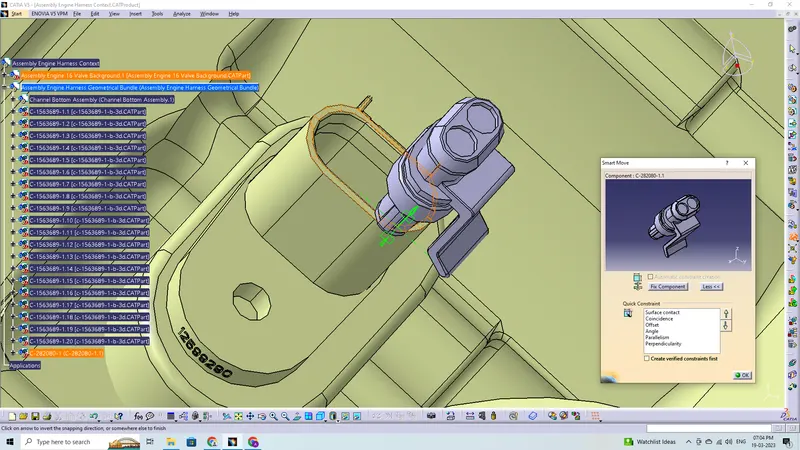
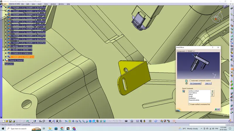
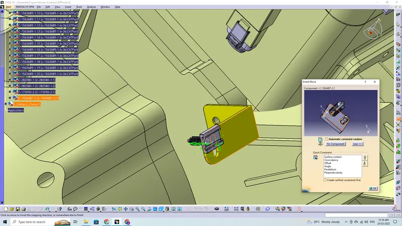
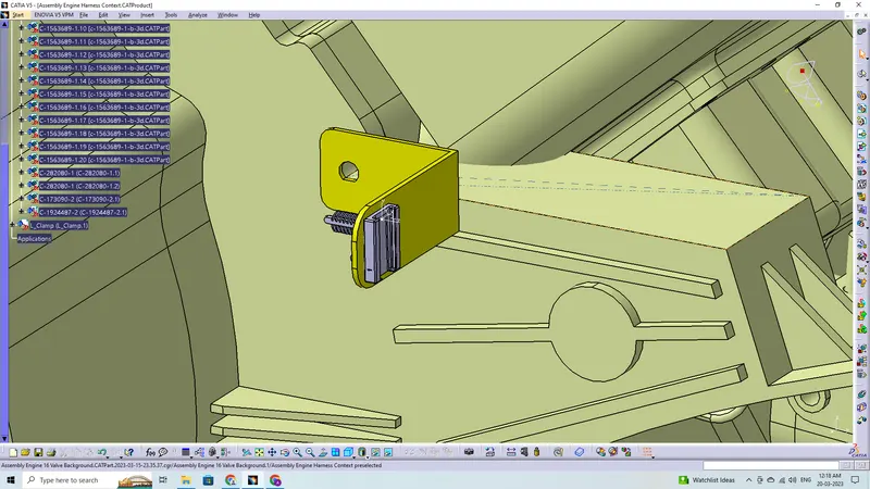
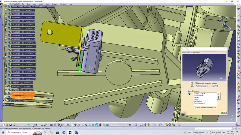
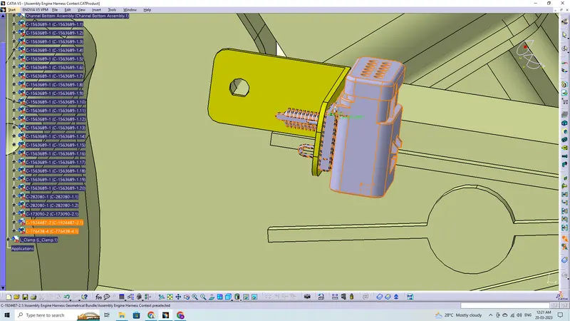
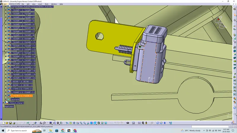
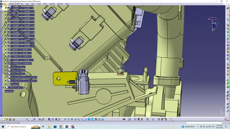
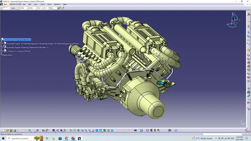
Assuming the engine's right side is where the bundle connection from the chassis is coming from, an L-Clamp is included to provide the interconnection connector with the required support. In this instance, the cavity clip is put into the L-Clamp's hole. The chassis bundle connecting to the engine harness interconnection connector has to have more slack to protect the wiring harness from vibrations brought on by the operation of the vehicle. The L-Clamp is mounted to one of the screw-mounting holes on the engine block as shown in the aforementioned images, and it is resting against the ribs to prevent it from rotating while the screw is being tightened. We can also see that the Interconnection Connection has been fitted and is electrically connected to the cavity that has been made available for it. As the L-Clamp is not included in either the Geometric or the Wire Harness bundles, it should be added to the main product.
Adding Support Components
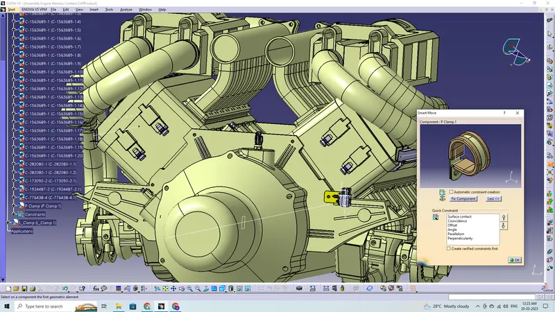
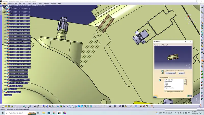
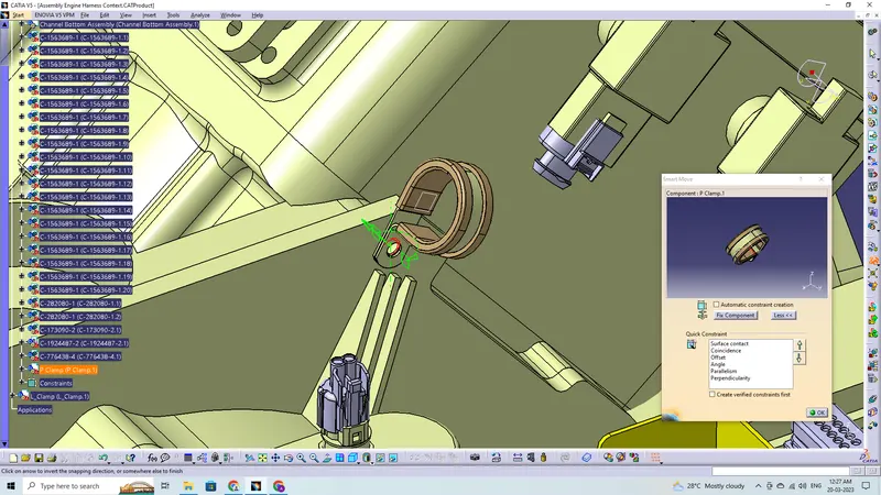
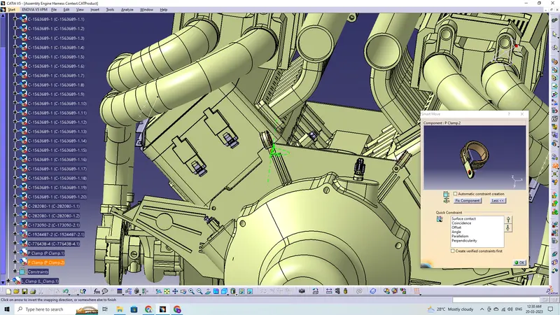
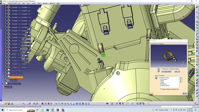
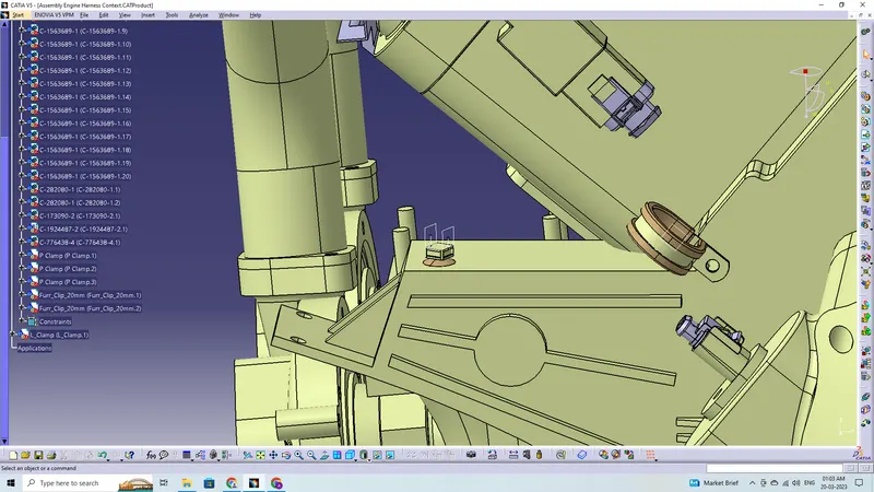
Adding supporting components like P-Clamps and Fir-Tree Clips can help the harness bundle provide proper routing and also help to prevent the harness bundles fouling from unwanted mechanical components.
- P-Clamp and the Fir-Tree Clip can be placed at required locations to ensure best possible routing for the harness bundles.
- The P-Clamps can be mounted to the holes provided on the Engine block in which the screws to tighten the Engine block.
- The Fir-Tree Clips are positioned according to the requirement during the wire harness routing.
Routing the Wiring Harness to the Connectors:
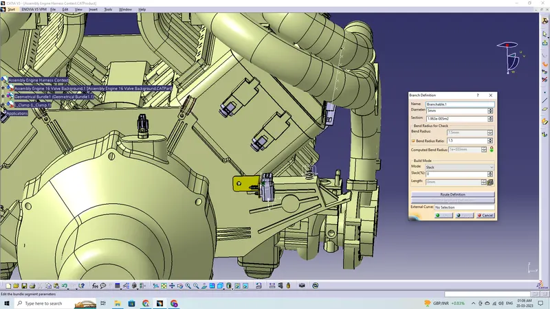
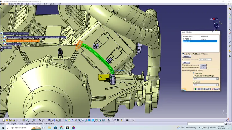
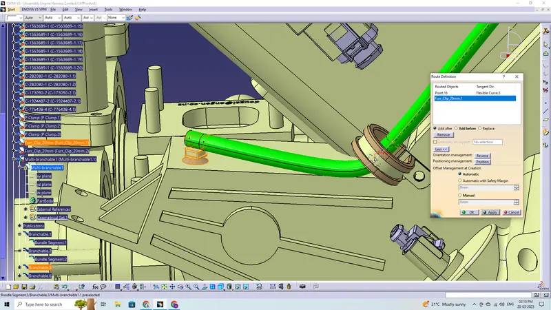
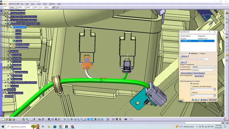
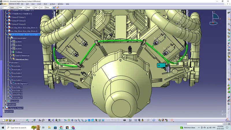
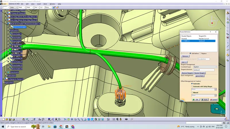
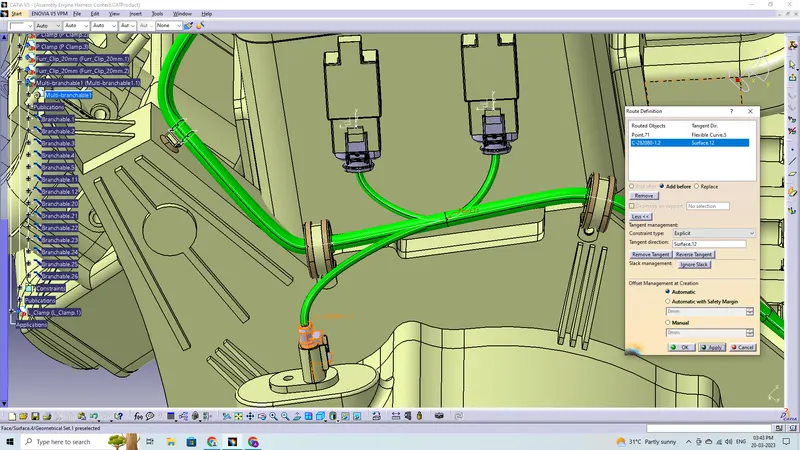
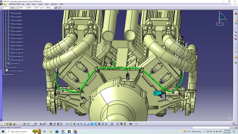
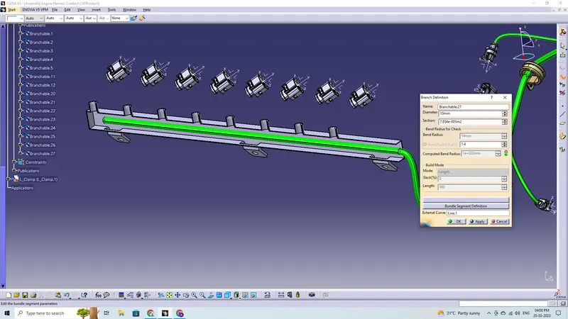
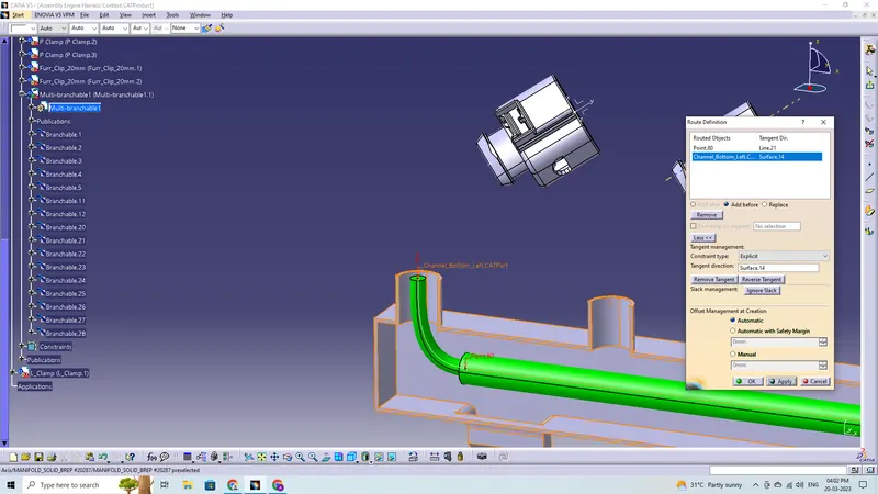
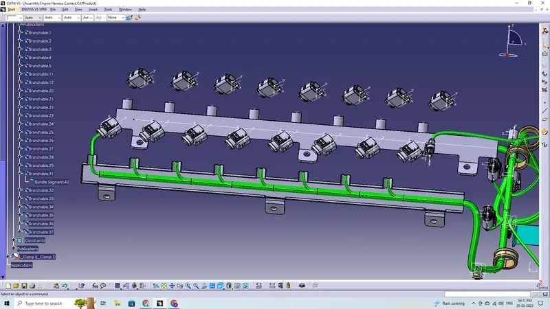
Choose the geometrical bundle in the model tree by going to the electrical harness assembly workbench and using the geometrical bundle command. To begin the bundle routing, choose the multibranchable command, and then navigate to route definition.
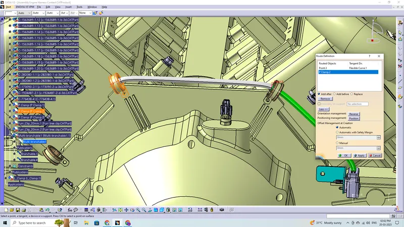
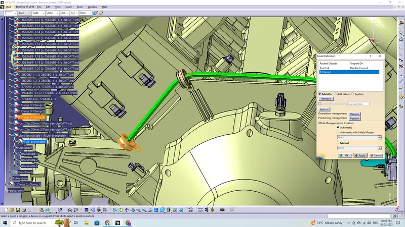
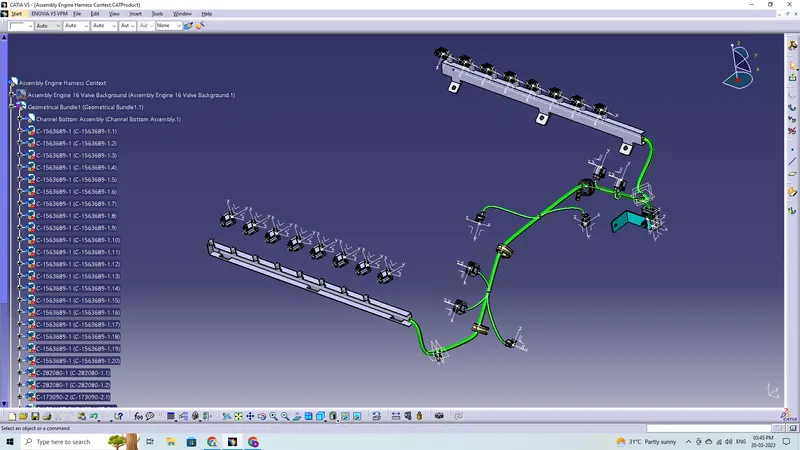
- The bundle routing starts from interconnection connector and then to the P-clamps and to the guiding channels
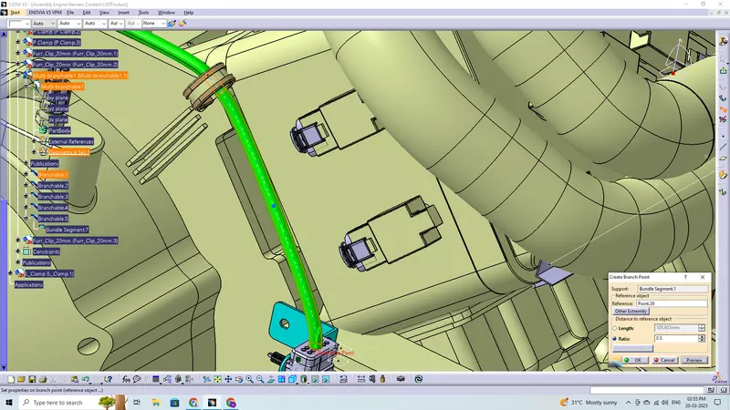
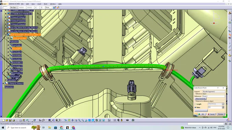
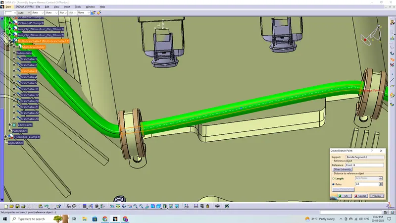
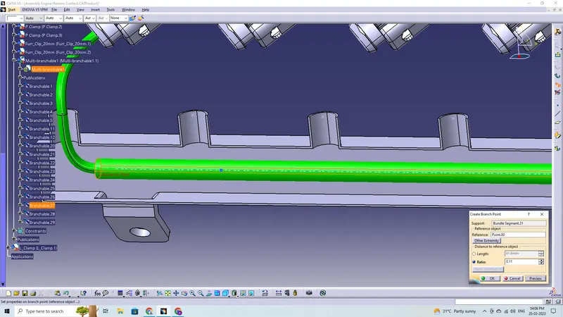
- Add branch points wherever necessary using add branch point command
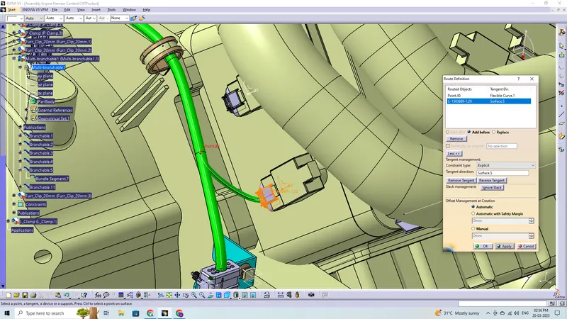
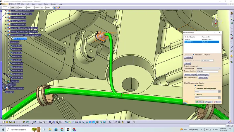
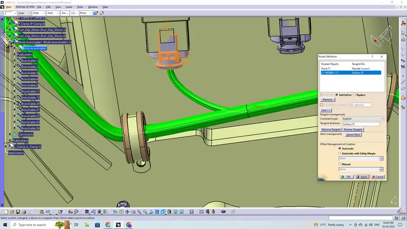
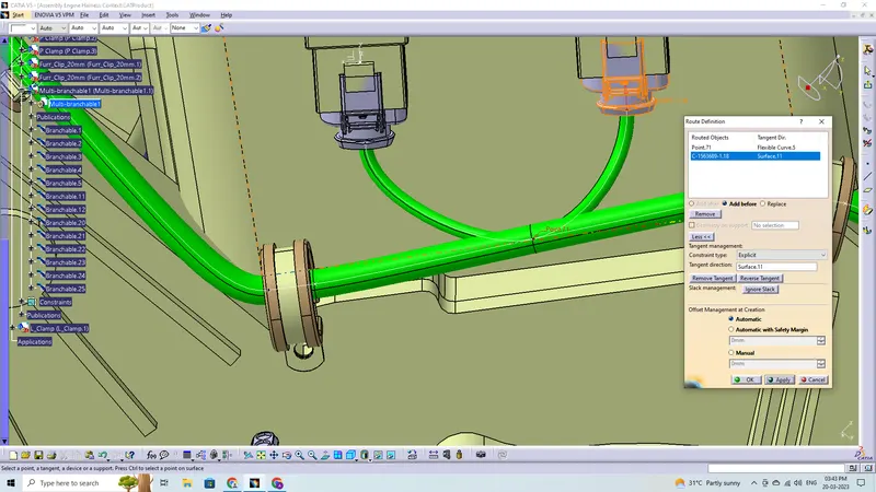
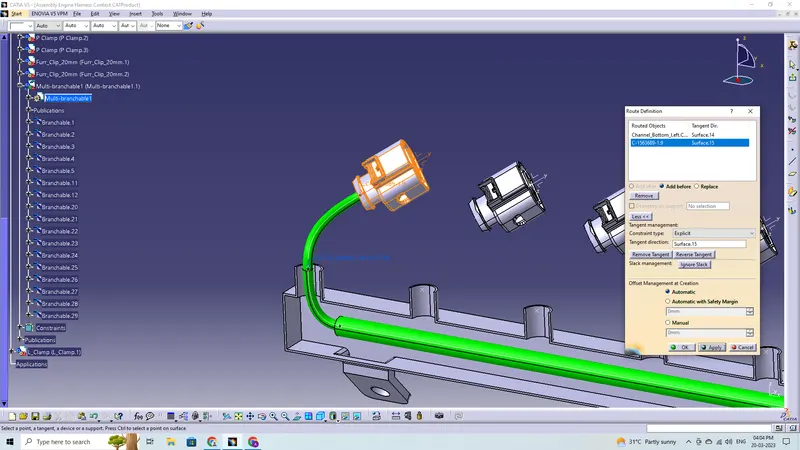
- Adding branches wherever necessary to connect the various connectors to the main branch and routing to it
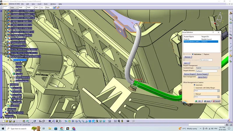
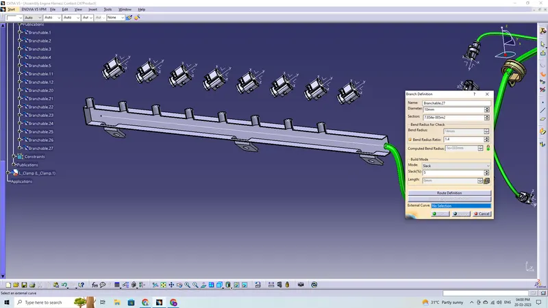
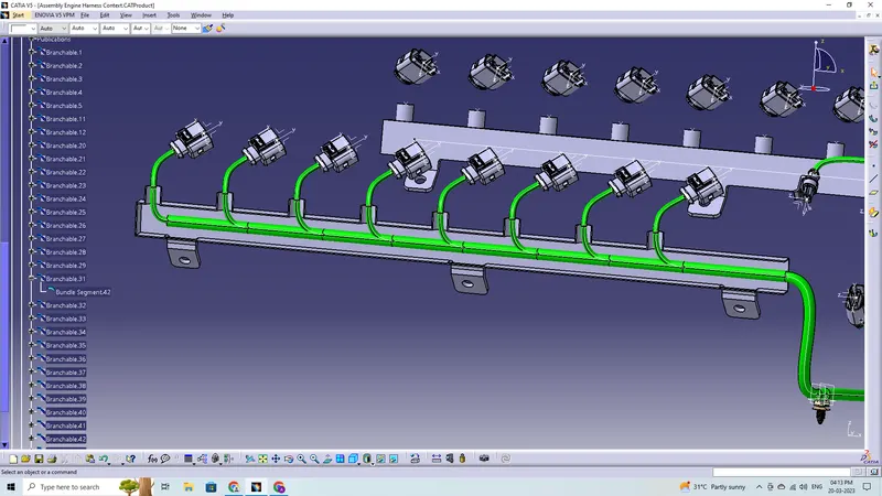
- To route the wiring harness through the guiding channels select external curve and click on the line in the guiding channel
- Add branching points to the wiring bundle and add branches to to connect the wiring to the connectors at the injectors
- Add guiding channel top to close the channel enclosure
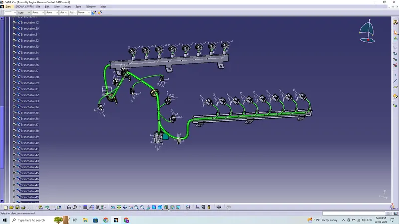
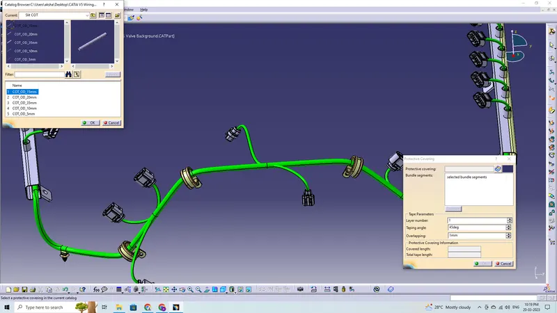
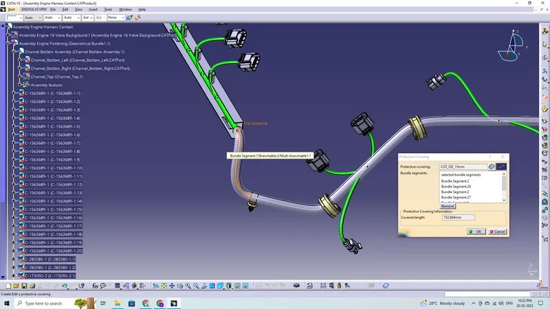
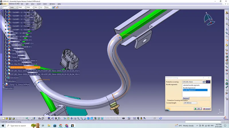
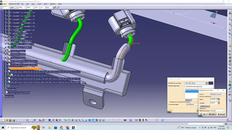
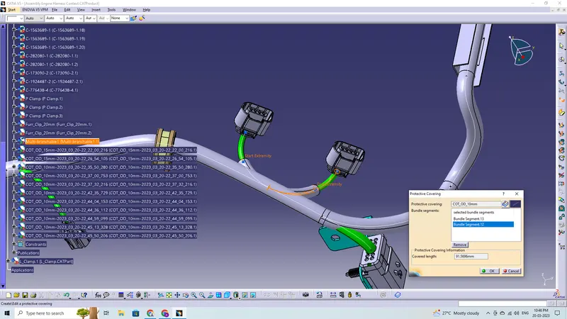
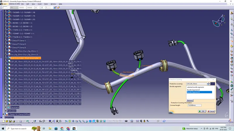
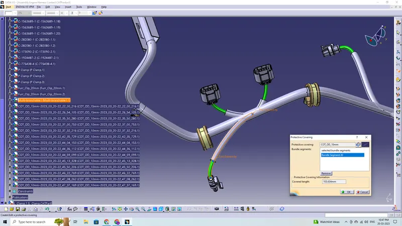
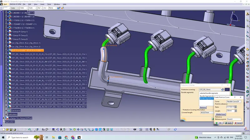
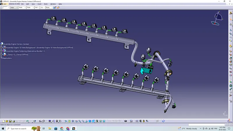
Corrugated Tube Protective Covering is applied
Now add the protective cover to the harness bundle by protective covering command in Electical Harness Assembly Workbench.
Checking Bundle Continuity:
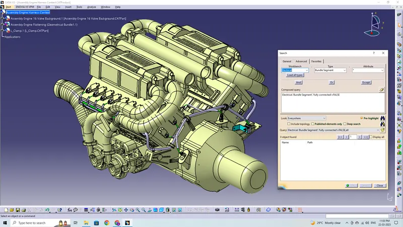
In this step, first we have to make sure that multi-branchable is selected then we have to go in Edit>Search>Advanced>
- By selecting 'True' option will show all the connected bundle segments while selecting 'False' option will show all the non-connected bundle segments.
- Here, we have selected for the 'False' option and searched for results. All the bundle segments are not found showing that all the bundle segments are electrically connected.
Flattening Harness:
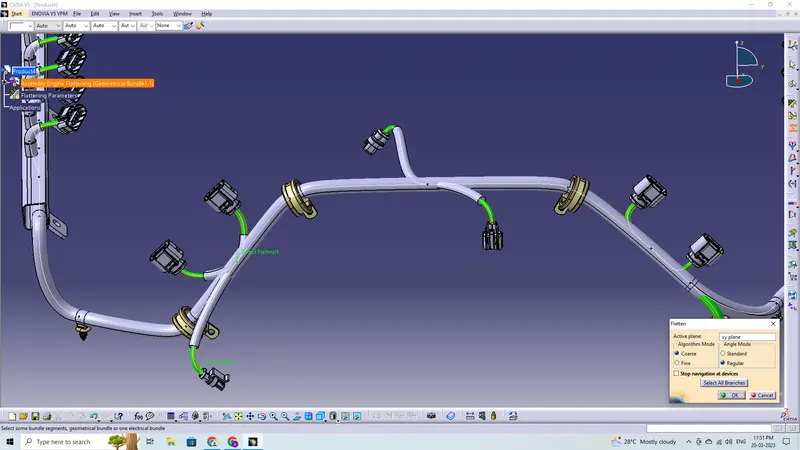
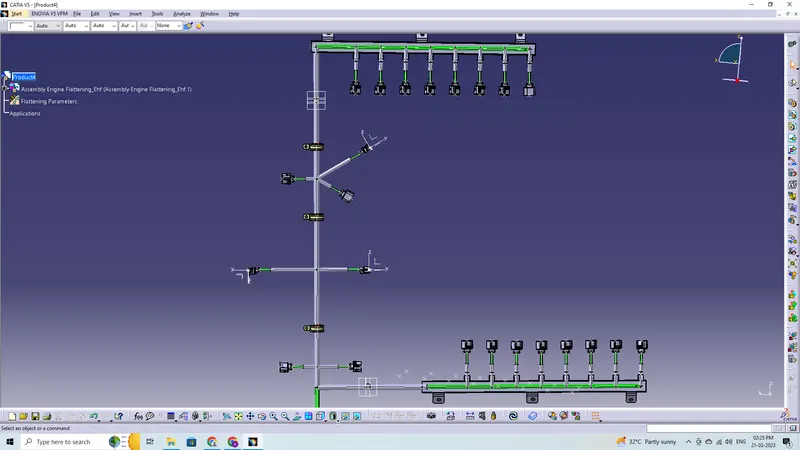
In this step, for creating flatten view we have to work in Electrical Harness Flattening Workbench of Catia V5. We should also make sure that the flattening file is saved in the same folder where other files of harness assembly are saved.
- Before creating flatten view, first we have to define flattening parameters. Make sure that selecting Single line for bundle segment and 'Double' line for protective covering.
- We have extracted the bundle assembly into Engine Harness Flattening Product file and Select the flatten command along XY plane and select the all-bundle harness segment
- Then flattened the file along face of interconnection connector
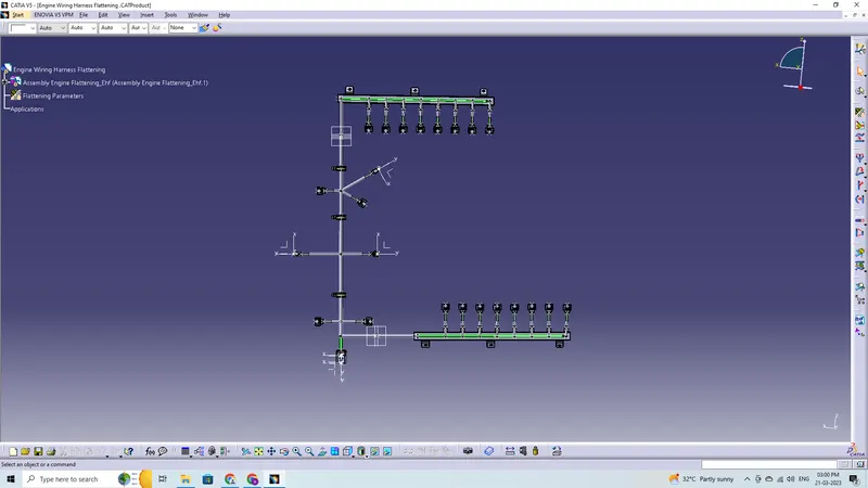
- Through manipulator command like rotate and bend adjust the harness for better representation.
- At this stage, for clarity, we have been hidden the flattening diagram of the plastic guiding channels from the drawing view.
Flatten View Drawing:
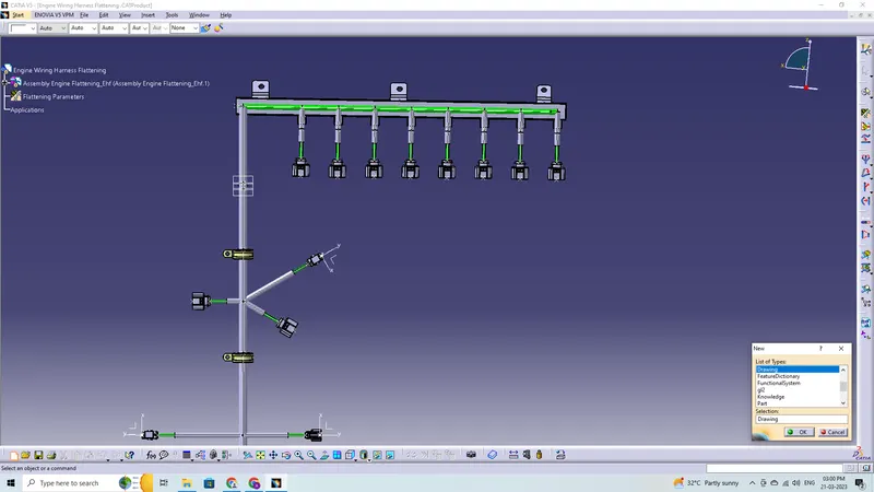
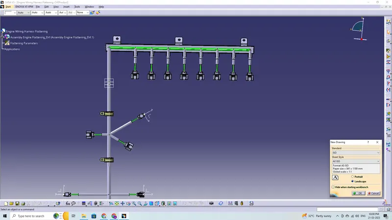
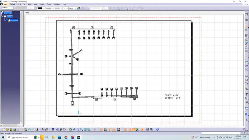
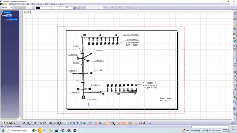
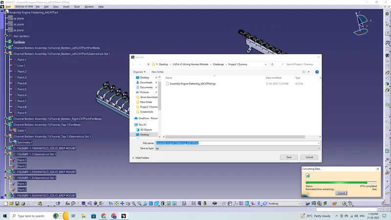
The final step is to convert our file into IGS format
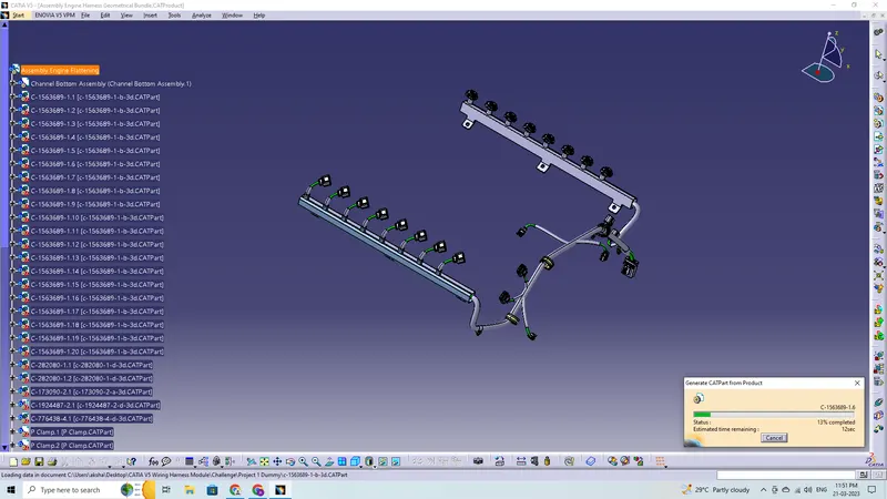
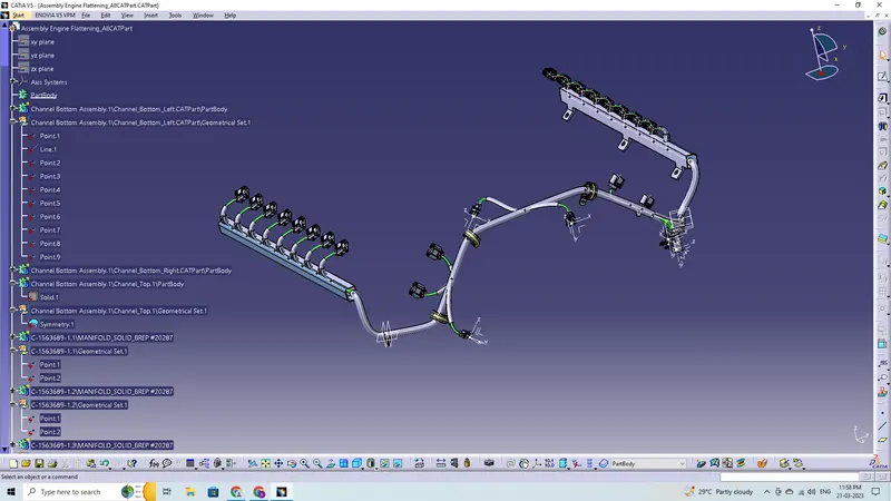
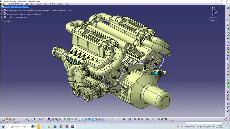
Final Look
Conclusion:
In this project, I was able to route the wire harness for the V16 Engine assembly, and CATIA V5 was used to create the flatten-view drawing. While routing the harness, various packaging regulations and restrictions were taken into account. The connector, clips, P-Clamp, and channel assembly have all the necessary properties applied to them. Bundles were given additional protective covering. The harness assembly was entirely flattened. Positioned the view that had been flattened on the design sheet.