Project 2
Statement of assignment:
Route the Wiring harness on Given car body and Prepare flatten view drawing in CATIA V5. Application of all Packaging rules, Industry best practices studied in this course shall be demonstrated in design. Apply Protection coverings as required.
Available connector 3D data can be used, or you can download the connectors from www.te.com
Prepare & Submit all necessary reports like clearance, Clipping/Clamping selection, Harness fixing requirements, Harness continuity, Assumptions if any along with CATIA 3D data.
Objective:
The objective of the project is to route the wiring harness on given Bugatti V16 Engine and prepare flatten view drawing in CATIA V5. All types of packaging rules have to be considered while routing the harness. Also, industry best practices should be demonstrated in design. All the necessary details like clearance, clipping/clamping selection, harness fixing requirements, harness continuity should be provided in order to design wiring harness.
- We are using an 4-pole electrical connector for the two tail lights and an 2-pole electrical connector for the two number plate lights.
- Also, we are using an 2-pole electrical connector for the defogging the rear windshield and another 2-pole electrical connector for the viper motor.
- Finally we are using a 4-pole electrical connector for the boot opening.
- Moreover, a car body has an interconnection connector that joins the wiring of the tailboard of the car body to the vehicle's main harness.
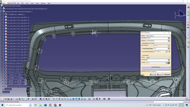
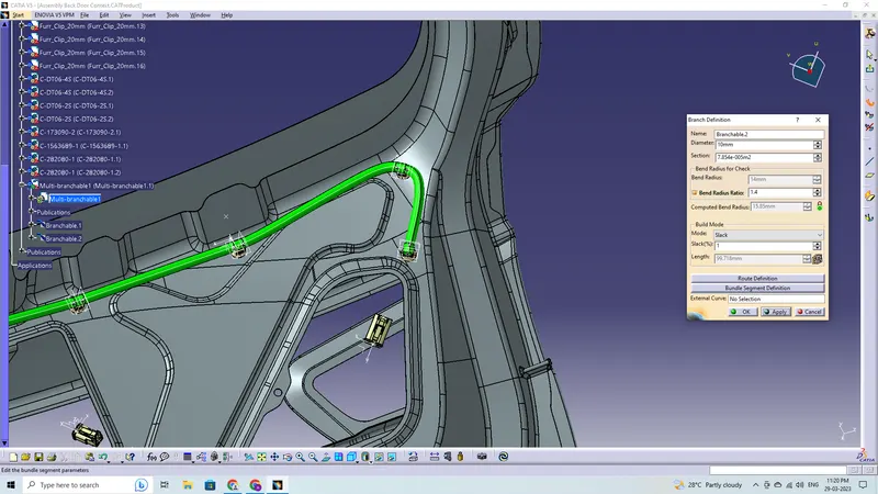
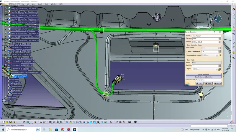
- All bundle segments are thought to have a bend ratio of 1.4.
Assumptions:
- It is important to route the wiring harness so that it is simple to assemble and access.
- When constructing the wire harness, easy manufacturing, installation, removal, and maintenance must be taken into account.
- Wiring Harness should not be exposed to harsh environments such as corners, edges, etc.
- While assembling or servicing a harness, avoid routing and clipping in regions that are difficult to access or in blind spots.
- In accordance with the surrounding conditions and the harness's bending requirements, add more slack if necessary. The envelope dimensions during door opening and shutting should be taken into consideration to allow slack if the harness is going through the closures/doors or tail gates. To prevent having too much slack, compare the required harness slack under both open and closed situations.
- Avoid passing through tiny structural apertures and holes to reduce handling and chaffing while installing the wiring harness.
- When designing the wiring harness in the CAD environment, it is important to ensure that there are no instances of fouling. To prevent fouling, additional mounting tools like clips or clamps may be employed.
- It is advised to use a rubber grommet if the harness must pass through sheet metal panels. For instance, a firewall, a path to a door, a tail gate, etc.
- More than 50mm should be present on the branch.
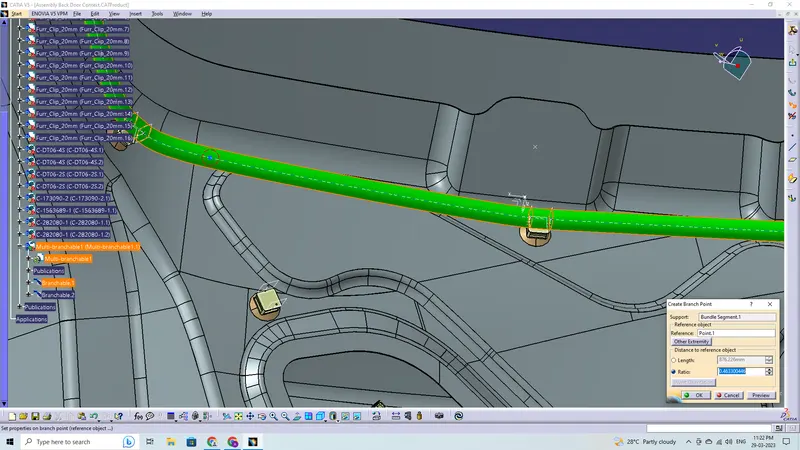
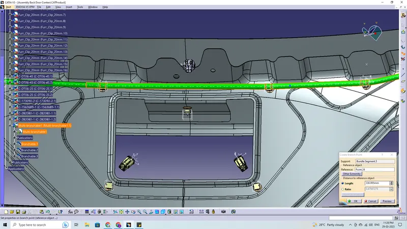
- There should be at least 25mm between the clip and the branch point.
- There should be at least 50mm between the two branch locations as a minimum.
- In order to avoid paying extra for specialised mounting solutions, the clips/clamps used for the wiring harness should be readily available on the market.
Parts used in Back Door Routing:
Connectors:
The given components are as follows:
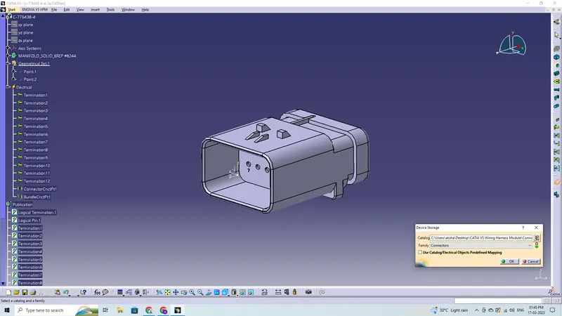
- C-776438-4-D-3D : Interconnection Connector
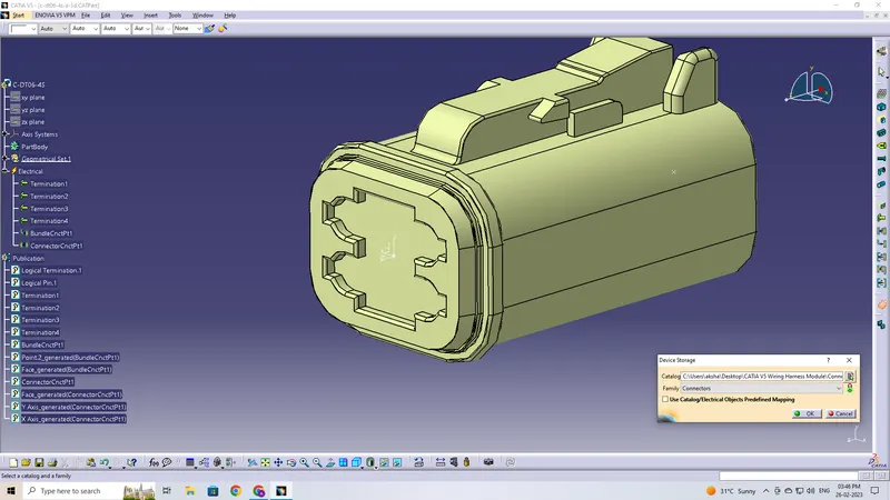
- C-DT06-4S-3D : Tail Lights
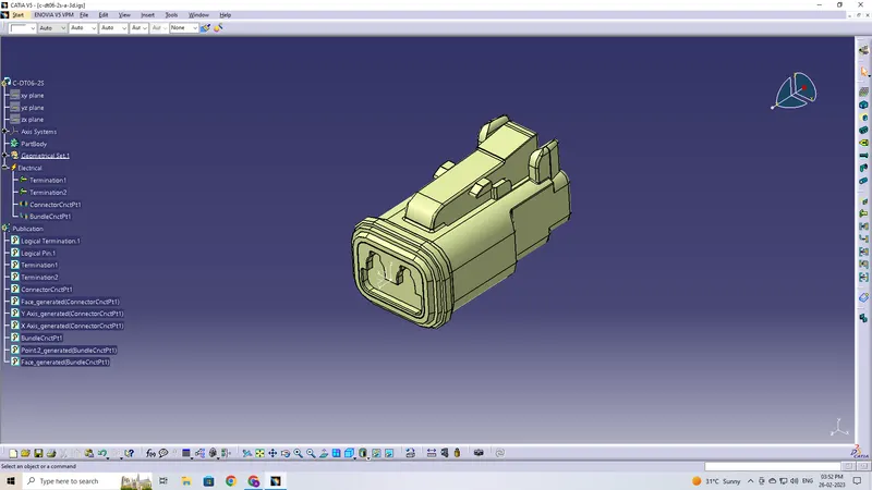
- C-DT06-2S-3D : Number Plate Lights
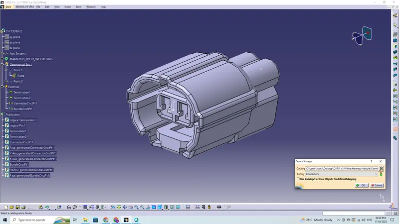
- C-173090-2-A-3D : Viper Motor
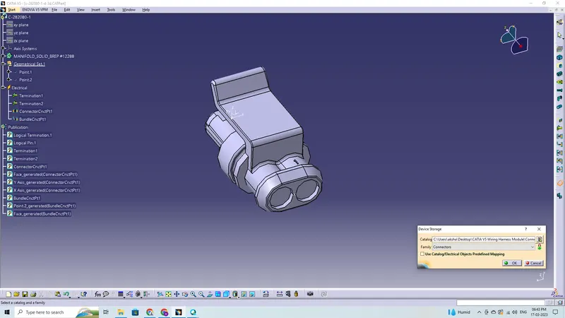
- C-282080-1-D-3D : Defogger
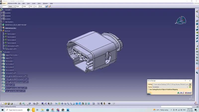
- C-1563689-1-B-3D : Boot Opening
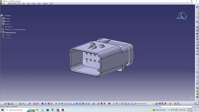
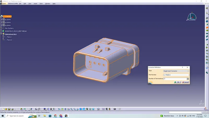
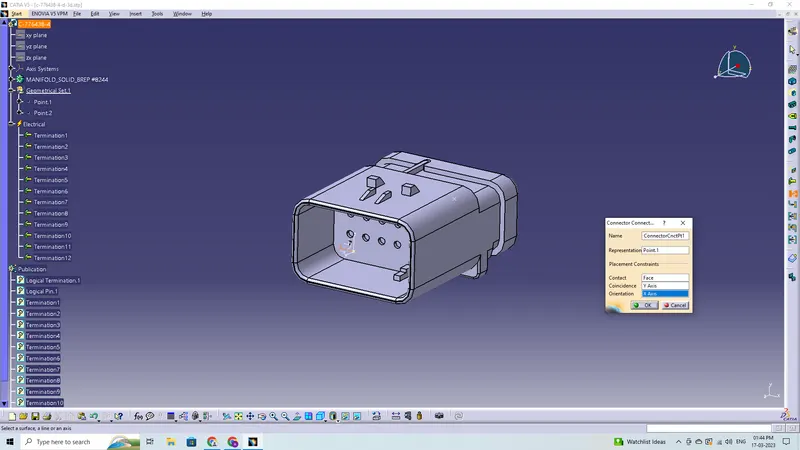
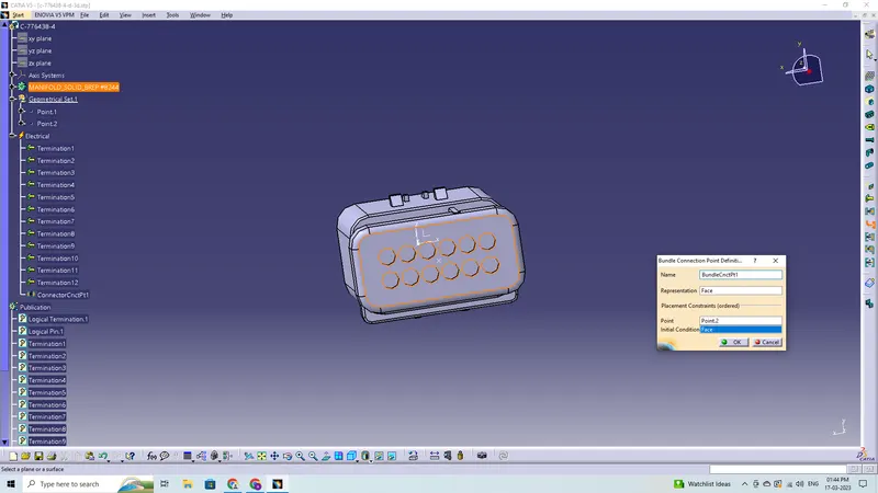
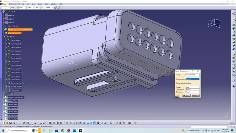
C-776438-4-D-3D
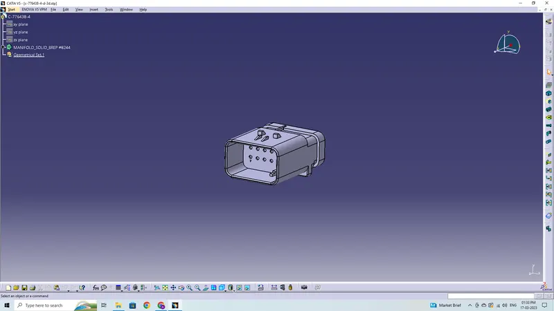
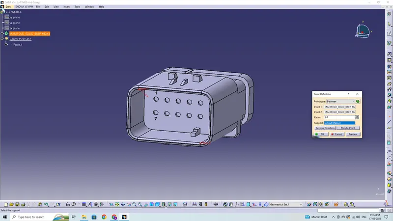
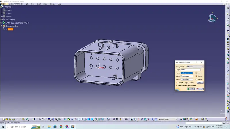
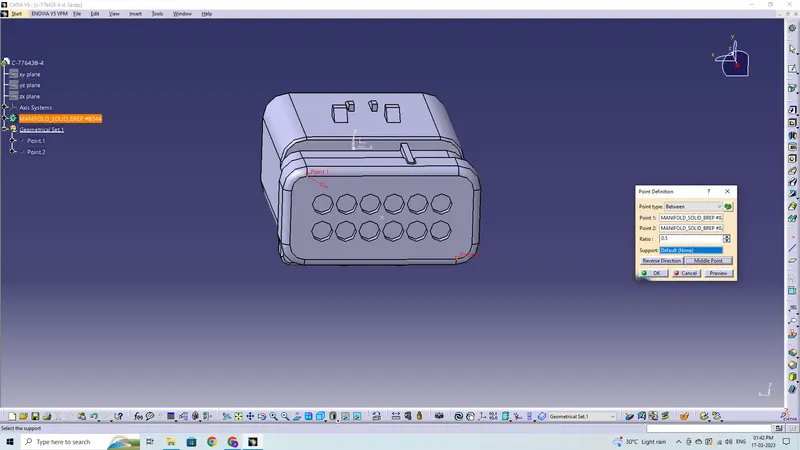
C-DT06-4S-3D
C-DT06-2S-3D
C-173090-2-A-3D
C-282080-1-D-3D
C-1563689-1-B-3D
These are the steps required to do in this project for connector definition-
- Create the required geometrical parameters for connector
- Create a bundle entry point
- If connector accommodates clip then define a geometrical parameter for the clip
- Define part as a connector or mounting equipment
- Create bundle connection point
- Create a connector connection point
- Create a cavity connection point if there is a clip
Clips and Clamps (Support Components):
The given component is as follows:
- Fir Tree Clip
Fir Tree Clip
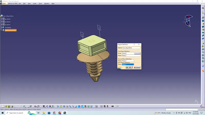
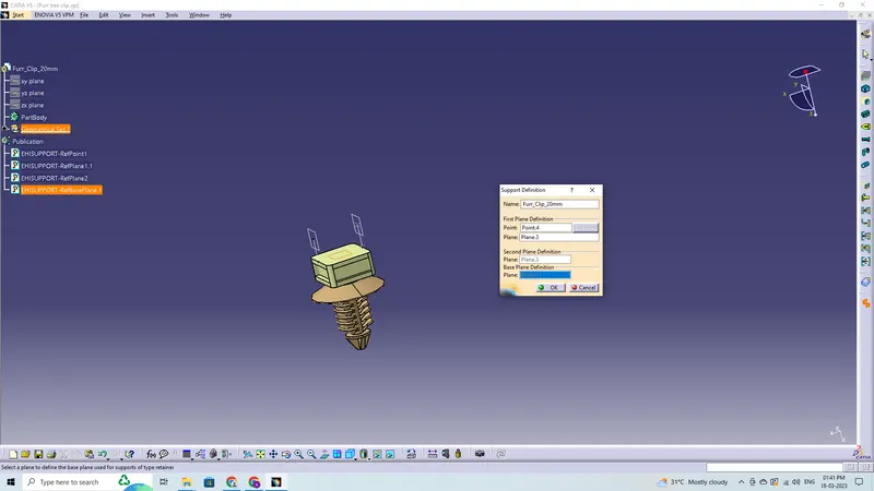
These are the steps required to do in this project for clips and clamps definition-
- Create the required geometrical parameters for the part
- Create entry point and entry plane
- Create exit plane and base plane
- Define part as electrical support
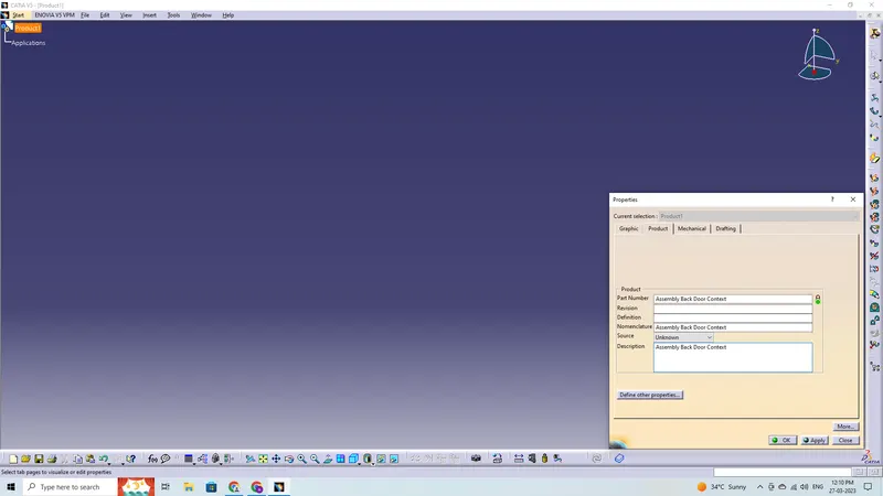
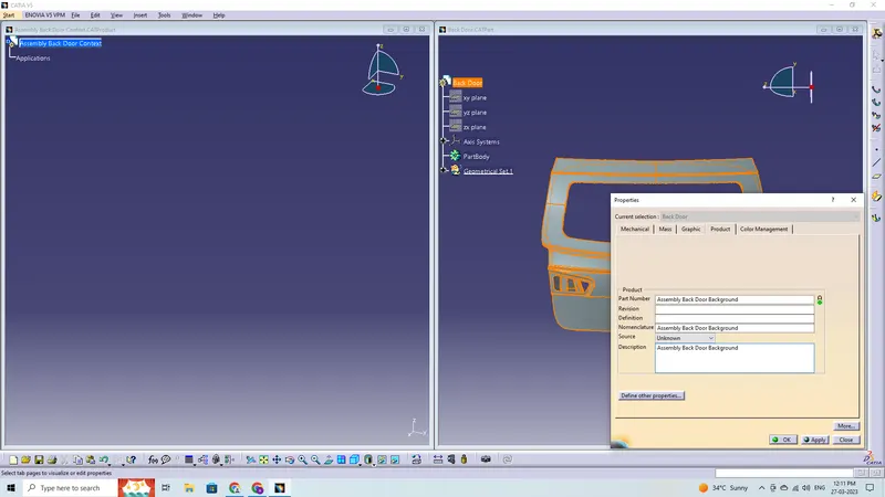
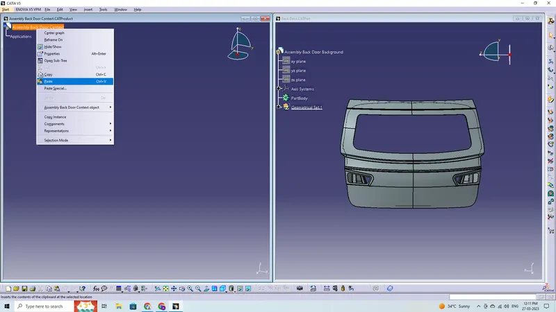
Context Assembly with Geometrical Bundle
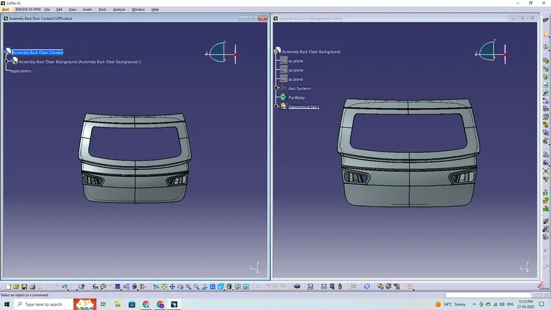
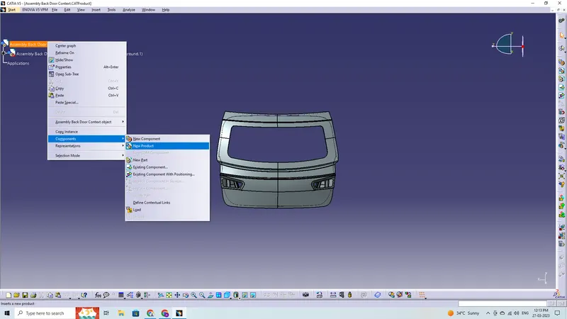
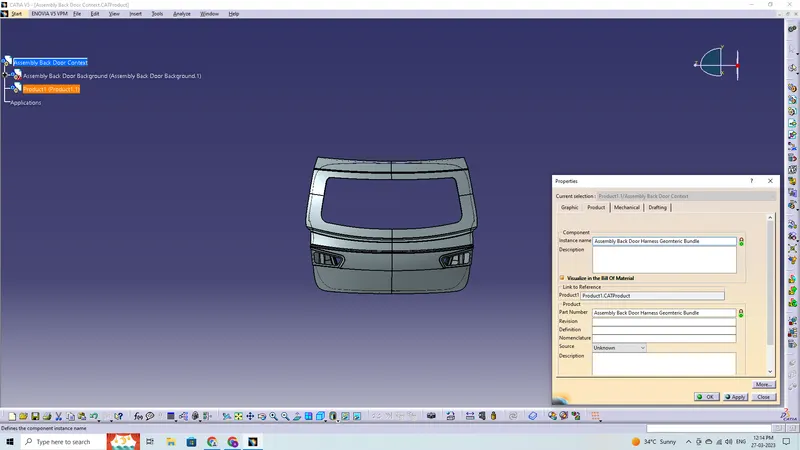
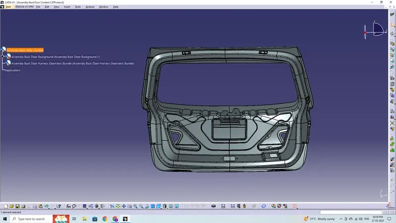
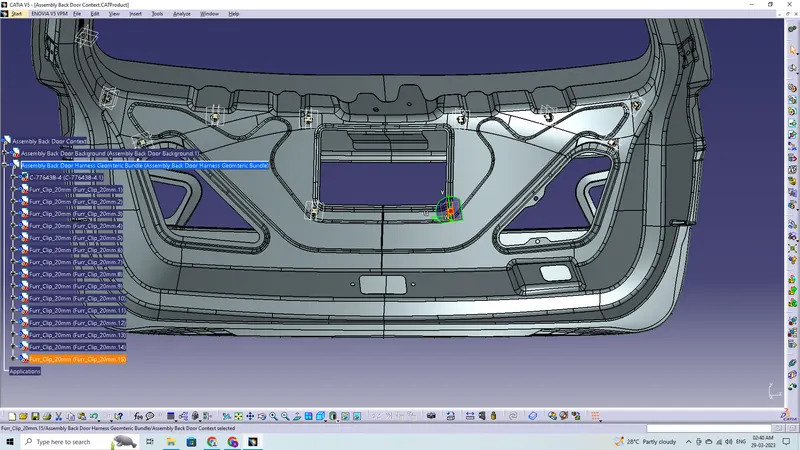
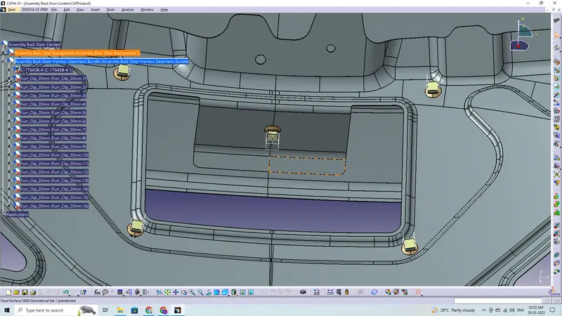
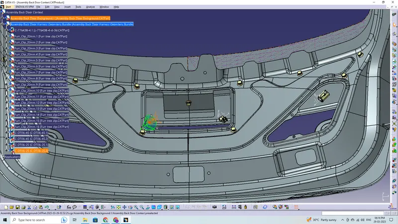
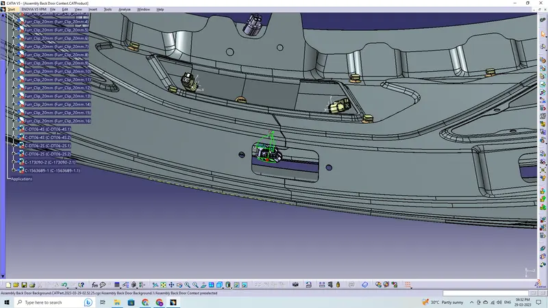
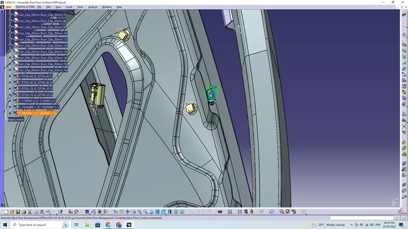
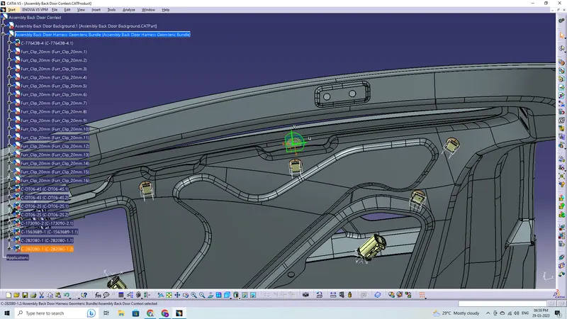
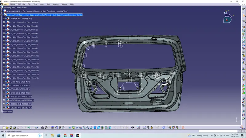
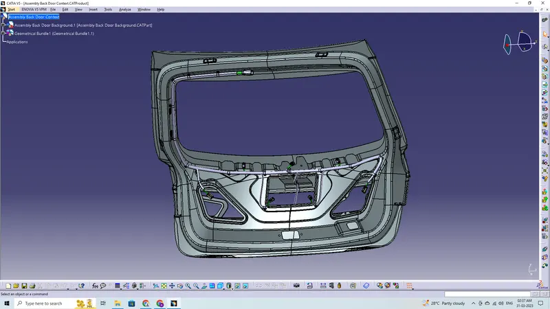
Context assembly is nothing more than the product file including the geometric bundle for the back door harness and the back door 3D-CAD data. All of the connectors, additional mounting tools, clips, and clamps that are electrically defined for the assembly are included in this geometrical bundle offering. Then we must go to the electrical harness assembly workbench, and before adding any parts, the Geometrical bundle product file needs to be electrically configured using the Define Geometrical bundle option.
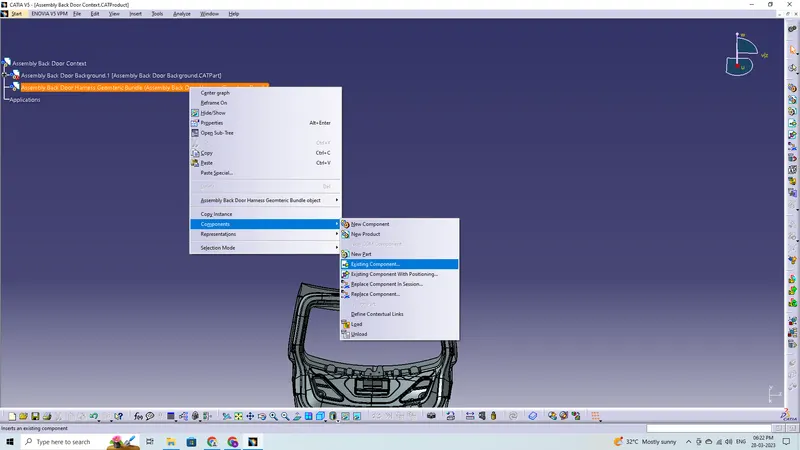
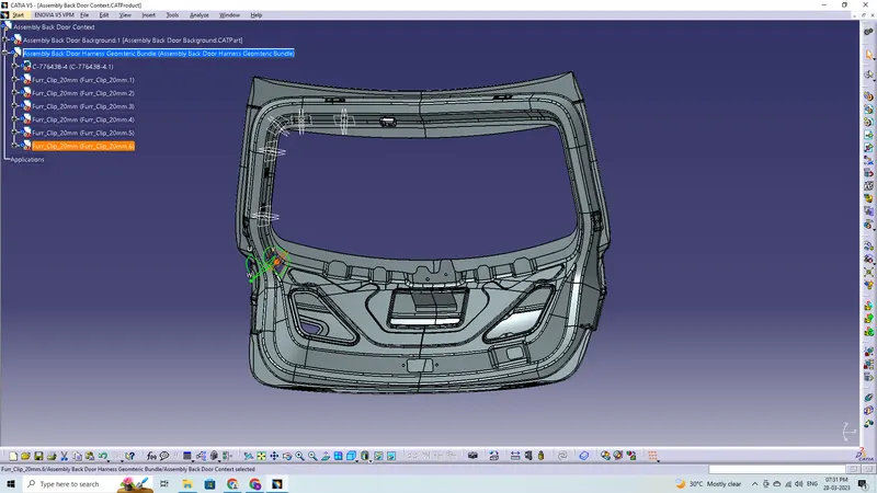
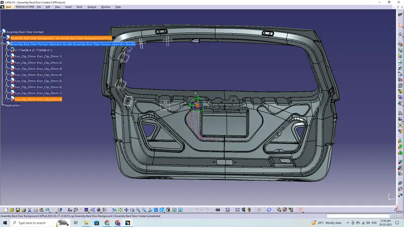
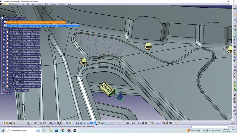
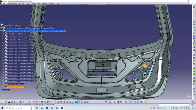
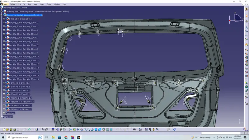
Adding 12-pole interconnection connector which will be connected to the main harness connection. Connectors can be added again by copy pasting the 1st imported connector. Place the connectors on all the respective desired location as decided; using the manipulation tools like move, smart move, snap tool and also using the compass. Adding all the other connectors like rear windshield defogger, tail lights, number plate lights, viper motor and boot opening according to their desired location.
Adding Support Components
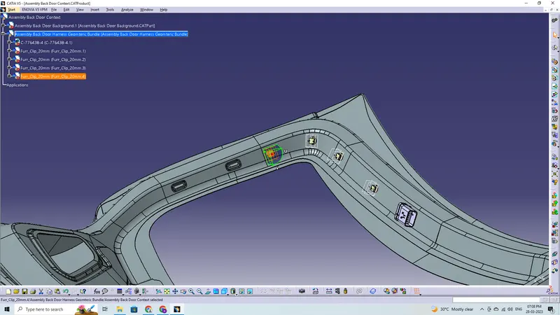
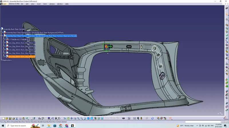
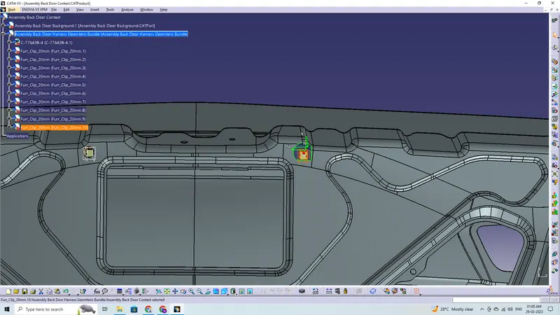
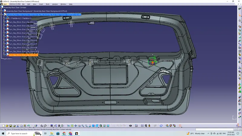
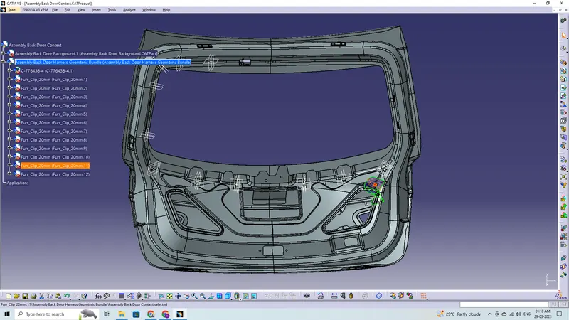
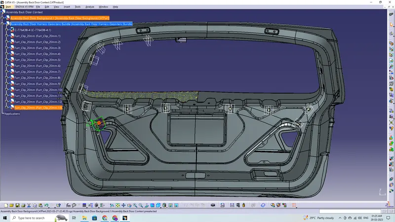
Adding supporting components like P-Clamps and Fir-Tree Clips can help the harness bundle provide proper routing and also help to prevent the harness bundles fouling from unwanted mechanical components.
- The Fir-Tree Clip can be placed at required locations to ensure best possible routing for the harness bundles.
- The Fir-Tree Clips are positioned according to the requirement during the wire harness routing.
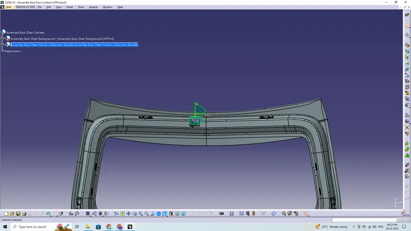
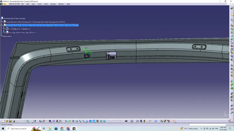
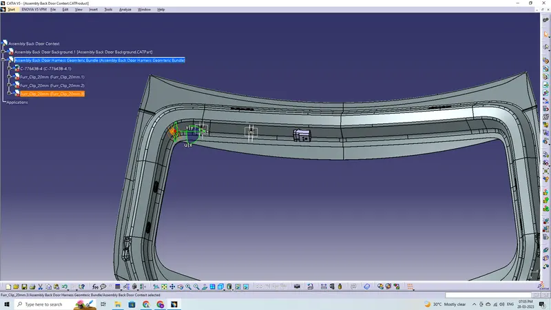
Adding and Placing the Connectors
Routing the Wiring Harness to the Connectors:
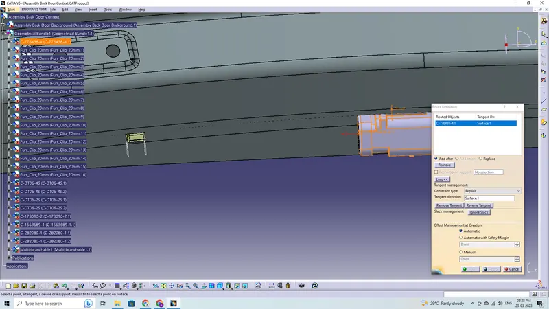
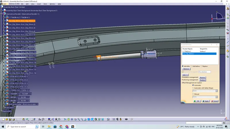
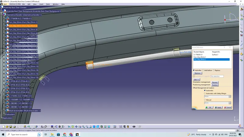
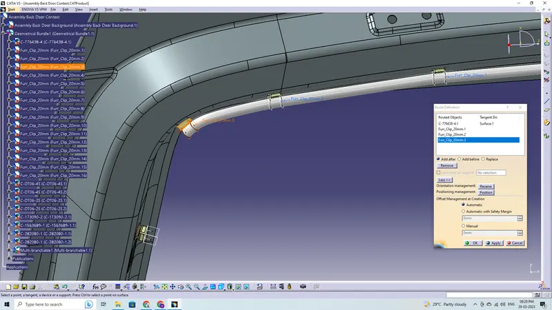
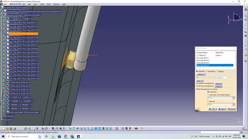
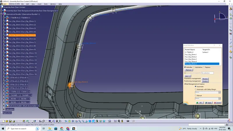
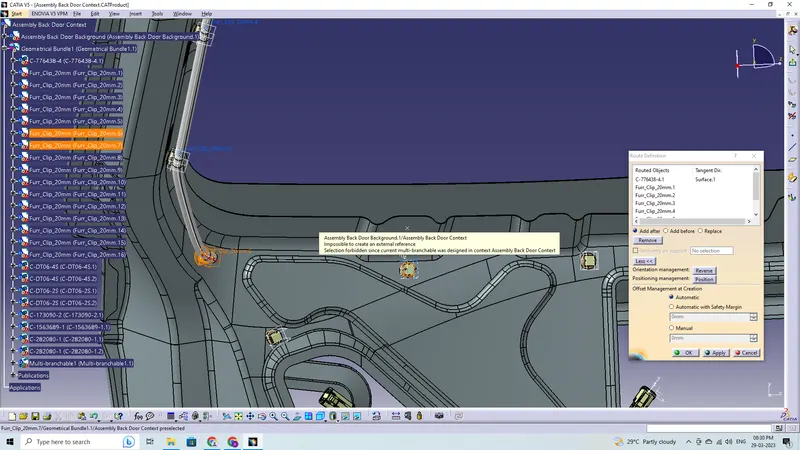
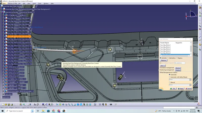
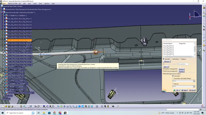
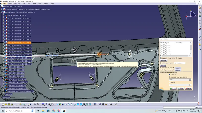
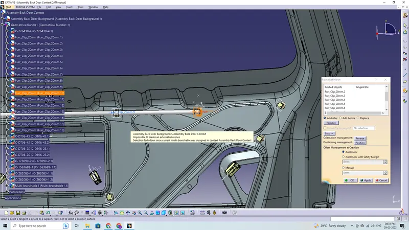
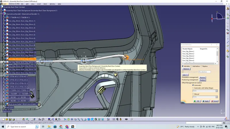
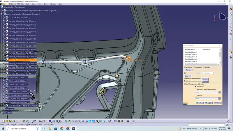
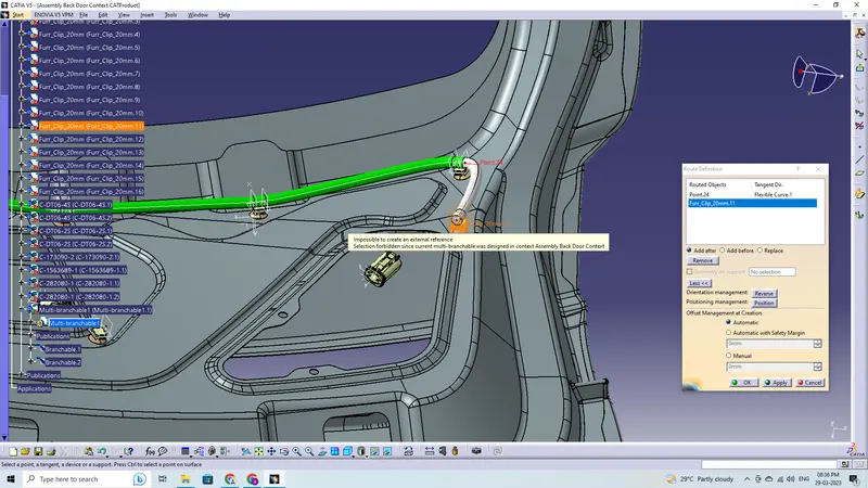
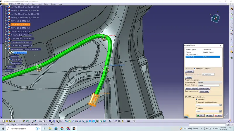
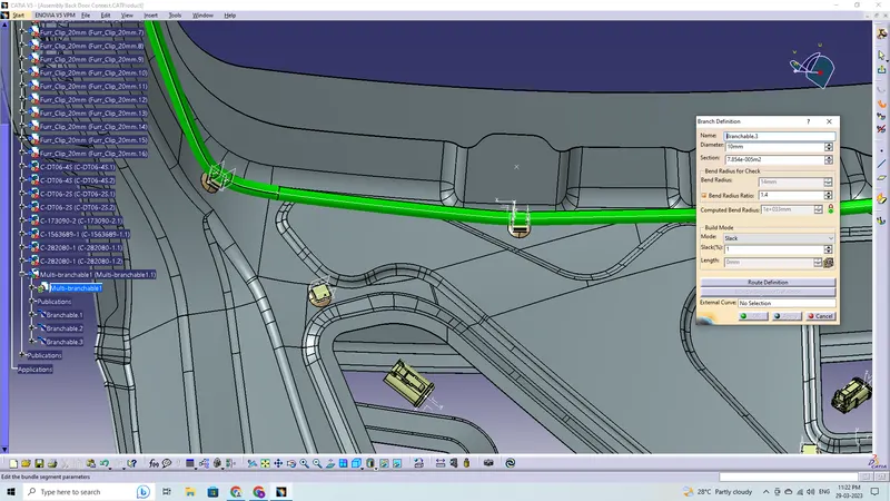
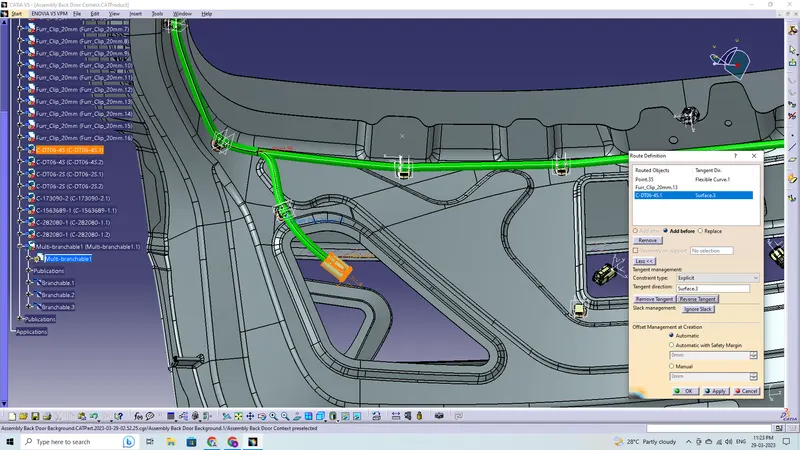
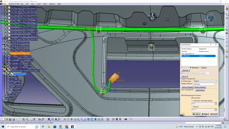
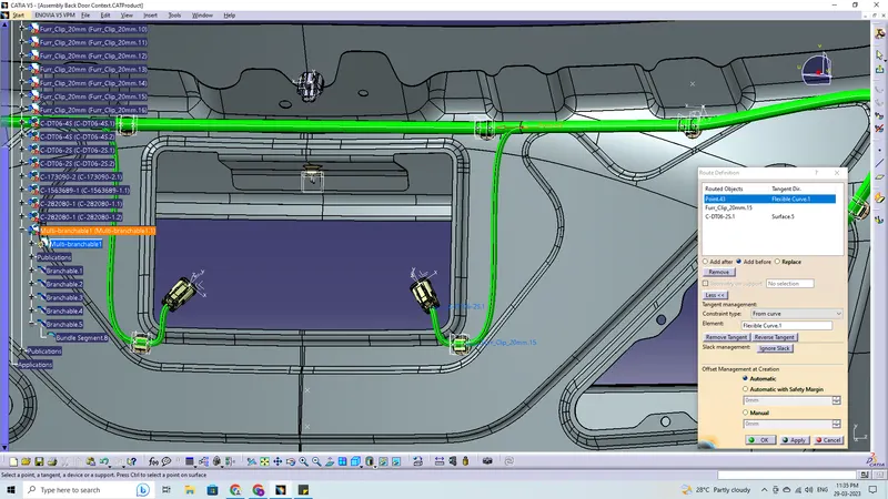
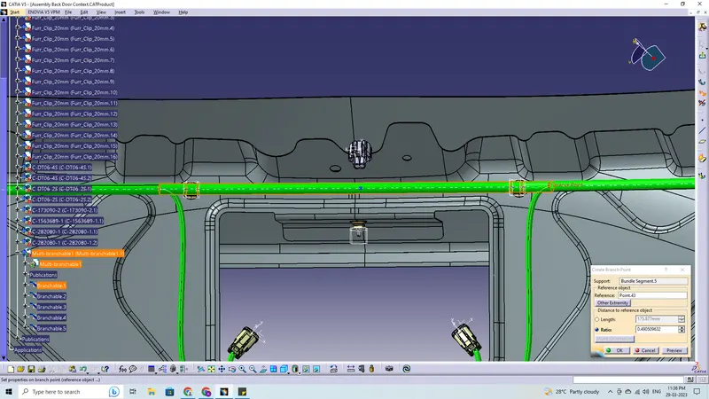
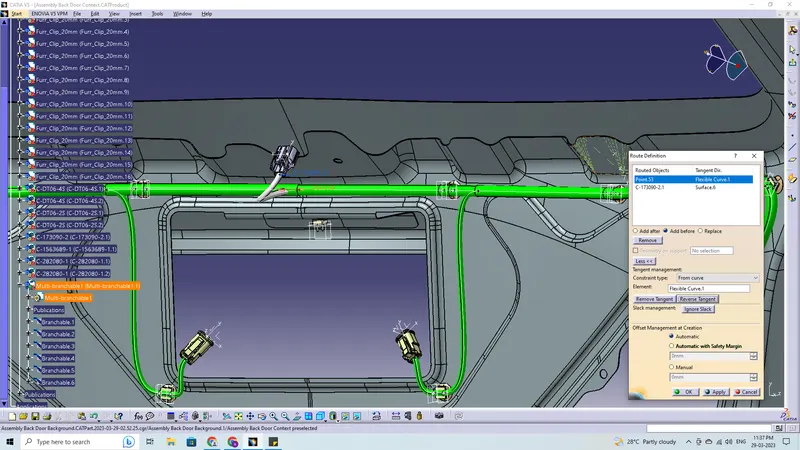
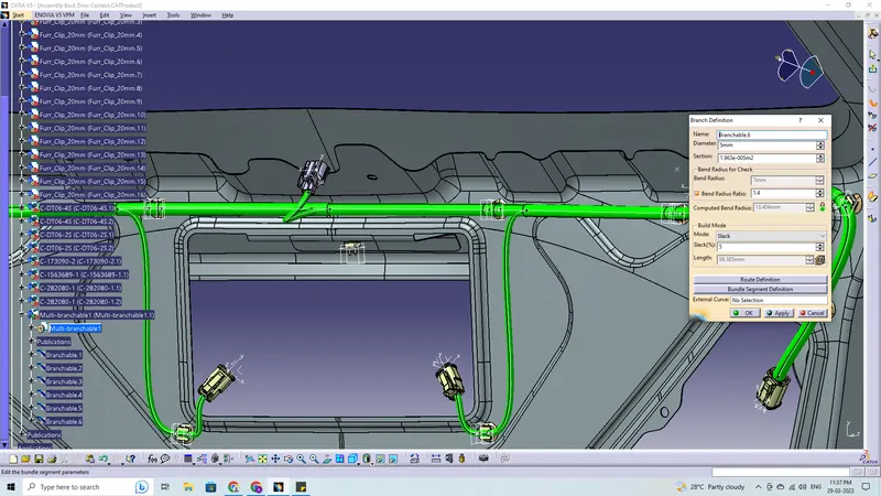
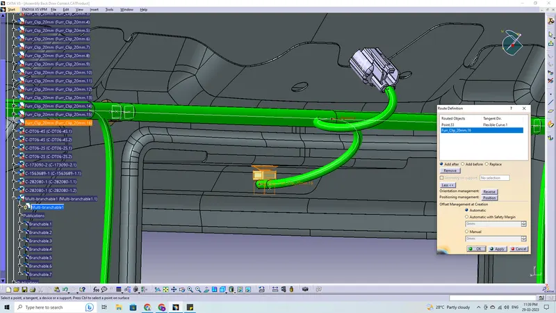
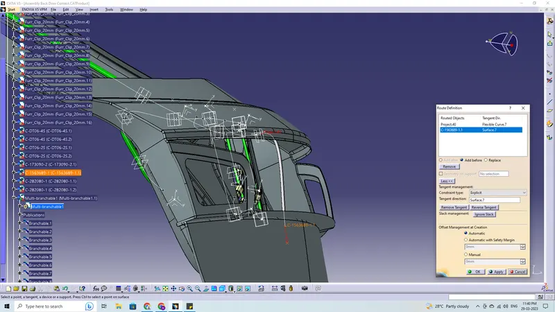
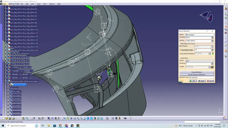
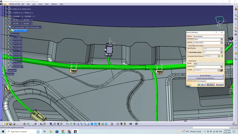
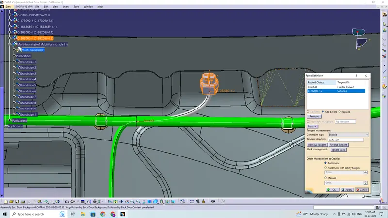
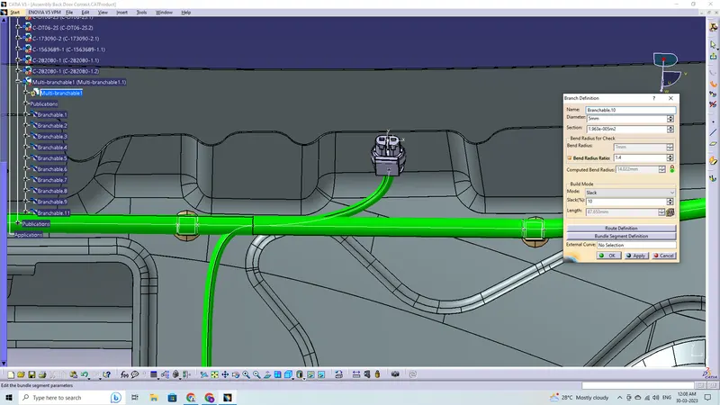
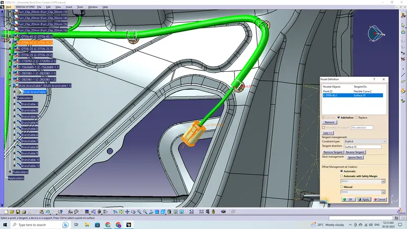
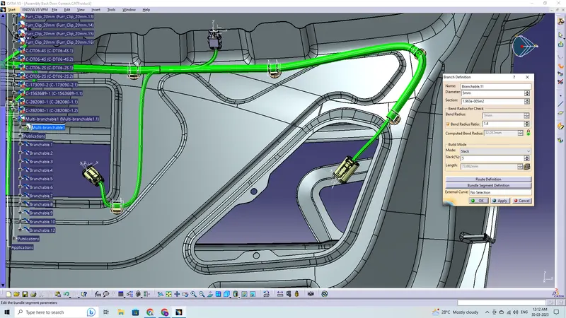
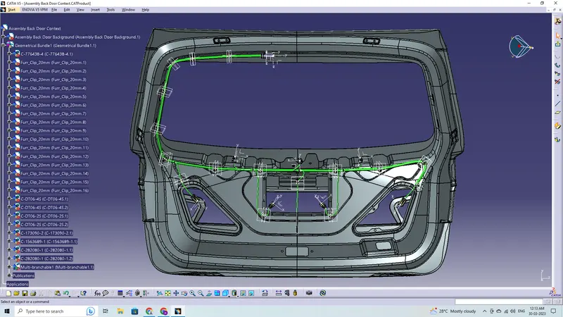
Choose the geometrical bundle in the model tree by going to the electrical harness assembly workbench and using the geometrical bundle command. To begin the bundle routing, choose the multibranchable command, and then navigate to route definition.
- The bundle routing starts from interconnection connector and then to the Fir-Tree clips and to the last connector which is right tail light.
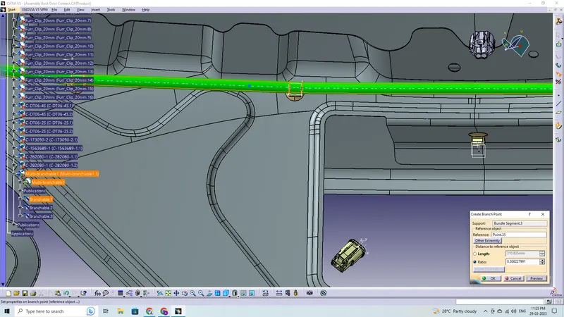
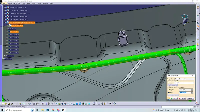
- Add branch points wherever necessary using add branch point command
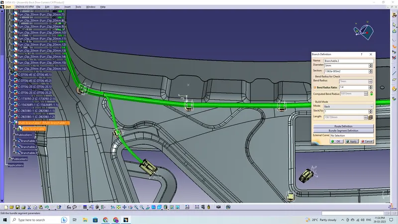
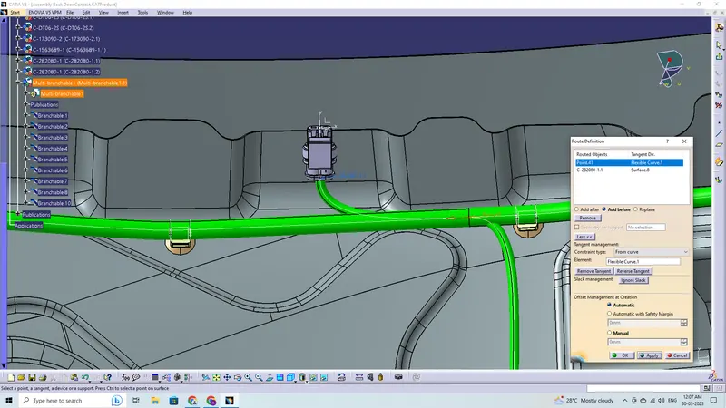
- Adding branches wherever necessary to connect the various connectors to the main branch and routing to it
- Add branching points to the wiring bundle and add branches to connect the wiring to the connectors
Checking Bundle Continuity:
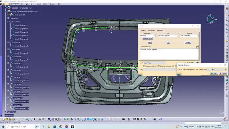
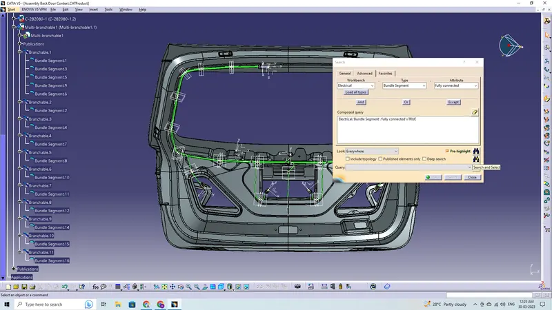
In this step, first we have to make sure that multi-branchable is selected then we have to go in Edit>Search>Advanced>
- By selecting 'True' option will show all the connected bundle segments while selecting 'False' option will show all the non-connected bundle segments.
- Here, we have selected for the 'True' option and search and select for results. All the bundle segments are found and selected showing that all the bundle segments are electrically connected.
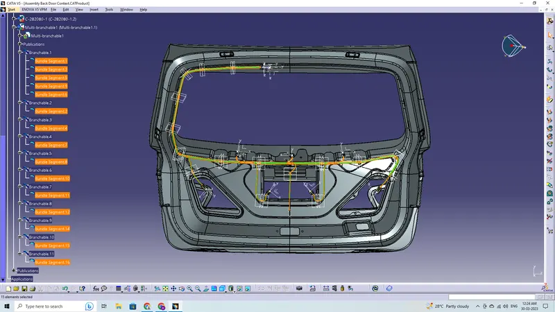
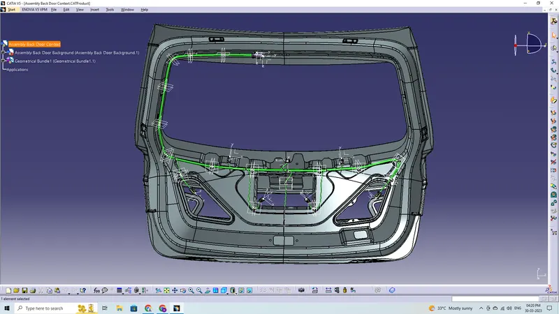
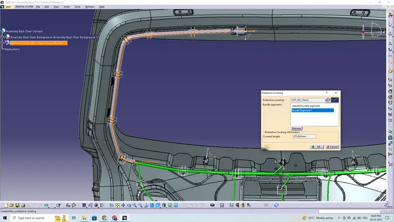
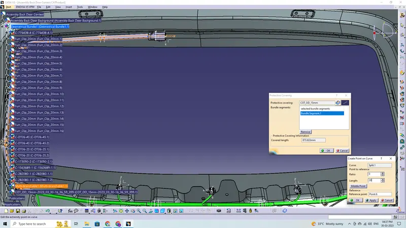
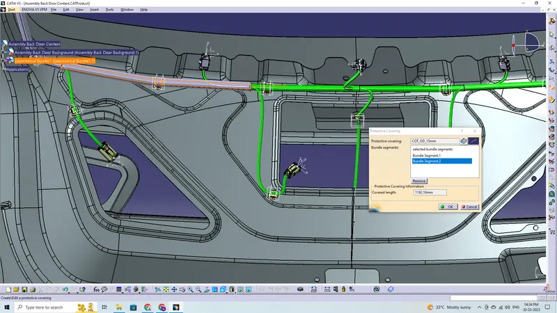
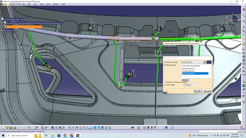
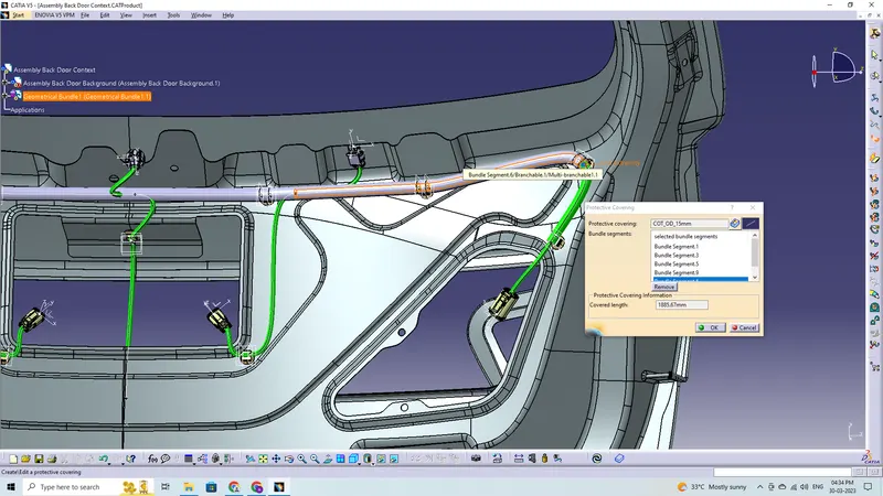
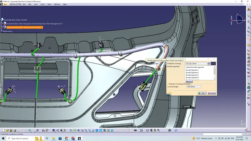
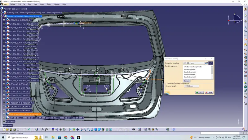
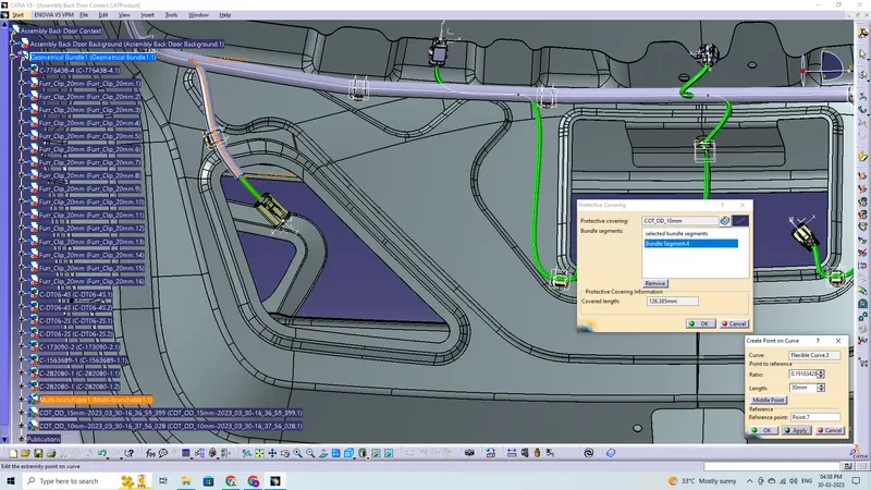
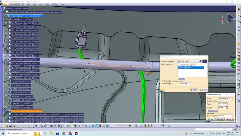
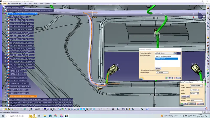
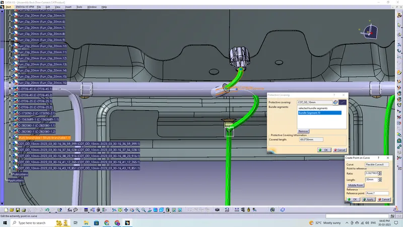
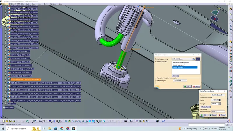
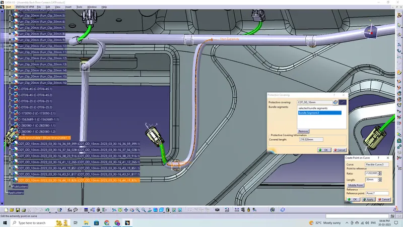
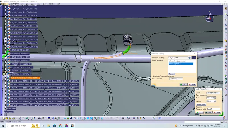
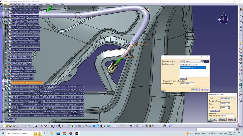
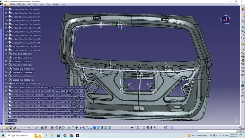
Corrugated Tube Protective Covering is applied
Now add the protective cover to the harness bundle by protective covering command in Electical Harness Assembly Workbench.
Flattening Harness:
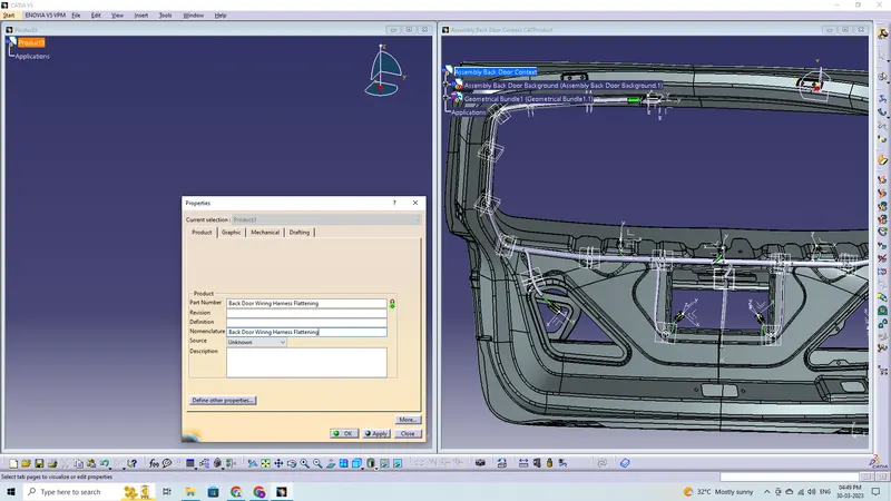
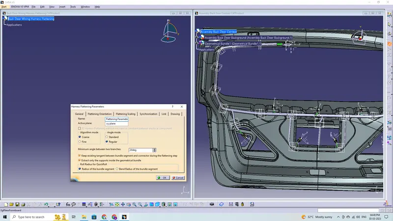
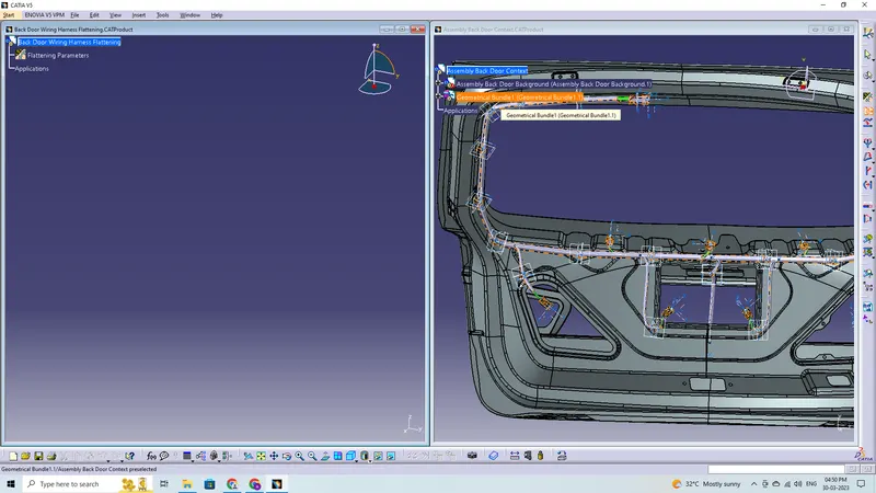
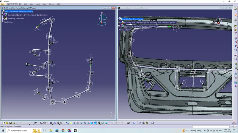
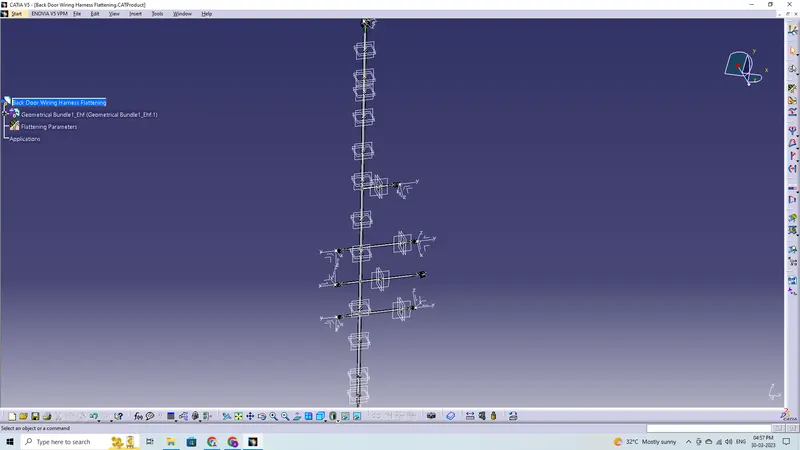
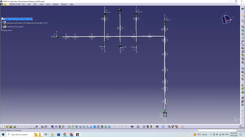
In this step, for creating flatten view we have to work in Electrical Harness Flattening Workbench of Catia V5. We should also make sure that the flattening file is saved in the same folder where other files of harness assembly are saved.
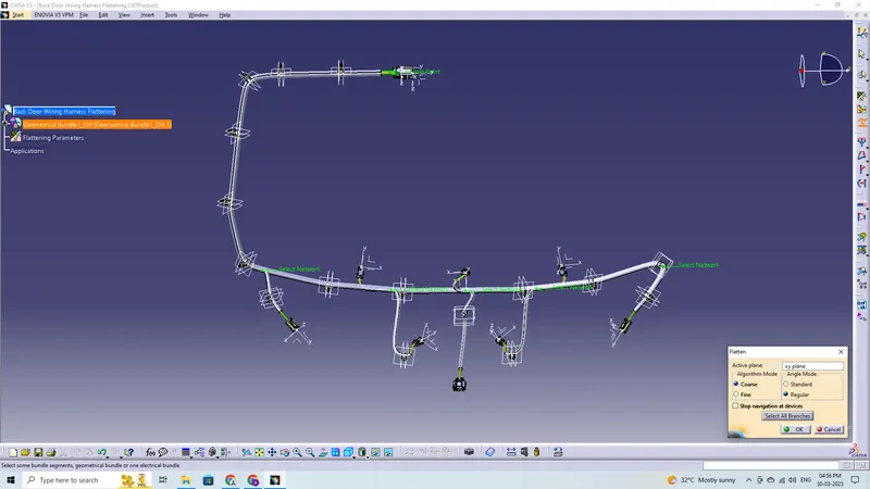
- Before creating flatten view, first we have to define flattening parameters. Make sure that selecting Single line for bundle segment and 'Double' line for protective covering.
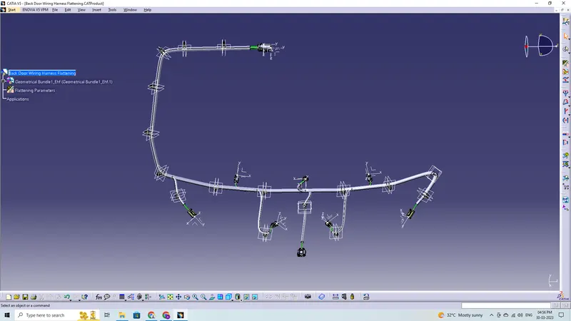
- We have extracted the bundle assembly into Engine Harness Flattening Product file and Select the flatten command along XY plane and select the all-bundle harness segment
- Then flattened the file along face of interconnection connector
- Through manipulator command like rotate and bend adjust the harness for better representation.
Flatten View Drawing:
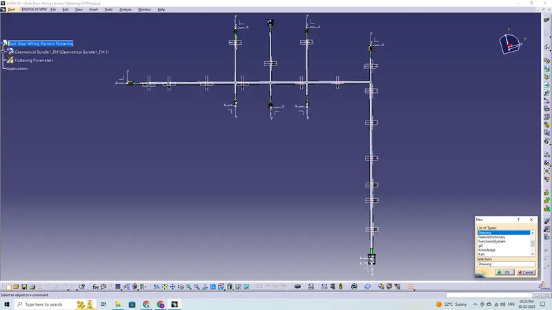
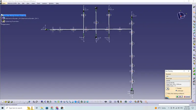
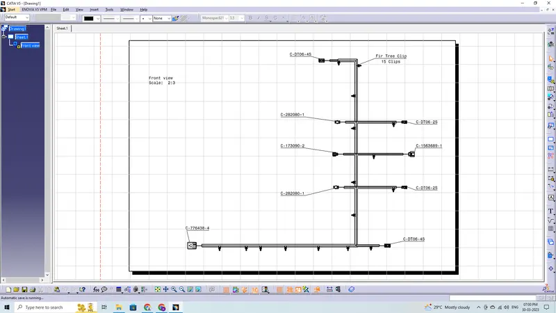
The final step is to convert our file into IGS format
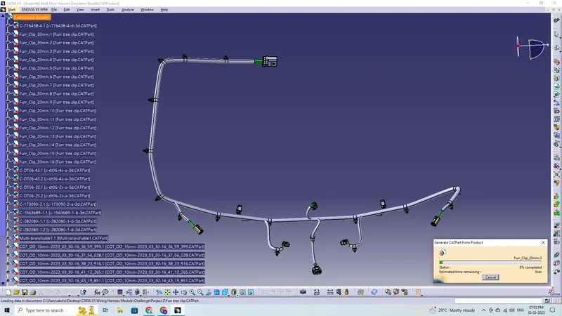
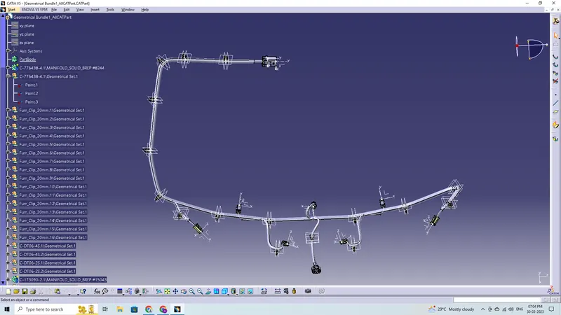
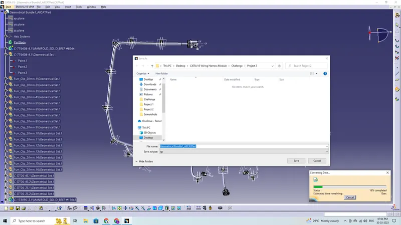
Final Look
Conclusion:
In this project, I was able to route the wire harness for the Back Door assembly, and CATIA V5 was used to create the flatten-view drawing. While routing the harness, various packaging regulations and restrictions were taken into account. The connector and clips, have all the necessary properties applied to them. Bundles were given additional protective covering. The harness assembly was entirely flattened. Positioned the view that had been flattened on the design sheet.