Project - Analysis of a practical automotive wiring circuit
Project - Analysis of a Practical Automotive Wiring Circuit
Aim: To analyse a practical automotive wiring circuit.
Objective:
1. Identify each of the major elements in the above automotive wiring diagram.
2. Explain the purpose and working of any three elements briefly.
3. If the total load is 10A from battery, what should be the fuse rating?
4. If 500W is the load, what is the voltage and capacity of battery you recommend?
5. Identify any two elements which are connected parallel to each other. Why they are connected in parallel?
6. Identify any two elements which are connected in series. Why they are connected in series?
Diagram:
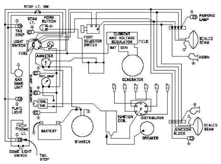
1. Identify each of the major elements in the above automotive wiring diagram.
The major elements in the above automotive wiring diagram are:
- Battery
- Starter
- Generator
- Ammeter
- Fuse
- Distributor
- Breaker
- Current and Voltage Regulator
- Ignition Coil
- Ground
- Junction Block
- Horns
- Lamps
- Lights
- Beams
- Horn Button
- Switches
- Gas Tank Unit
2. Explain the purpose and working of any three elements briefly.
The purpose and working of the three elements are briefly explained as follows:
a.) Battery: A battery is a device that is able to store electrical energy in the form of chemical energy, and converts that energy into electricity.
Working Principle: It works on the electrochemical oxidation-reduction reaction. This reaction involves the transfer of electrons from material (electrode) to another via an chemical material called an electrolyte.
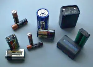
There are three main components of a battery: two terminals made of different chemicals (typically metals), the anode and the cathode; and the electrolyte, which separates these terminals. The electrolyte is a chemical medium that allows the flow of electrical charge between the cathode and anode. When a device is connected to a battery — a light bulb or a electric circuit — chemical reactions occur on the electrodes that create a flow of electrical energy to the device.
b.) Generator: An electric generator is a device that converts mechanical energy obtained from an external source into electrical energy as the output.
Working Principle: It works on the principle of electromagnetic induction. A conductor coil (a copper coil tightly wound onto a metal core) is rotated rapidly between the poles of a horseshoe type magnet. The conductor coil along with its core is known as an armature. The armature is connected to a shaft of a mechanical energy source such as a motor and rotated. The mechanical energy required can be provided by engines operating on fuels such as diesel, petrol, natural gas, etc. or via renewable energy sources such as a wind turbine, water turbine, solar-powered turbine, etc. When the coil rotates, it cuts the magnetic field which lies between the two poles of the magnet. The magnetic field will interfere with the electrons in the conductor to induce a flow of electric current inside it.
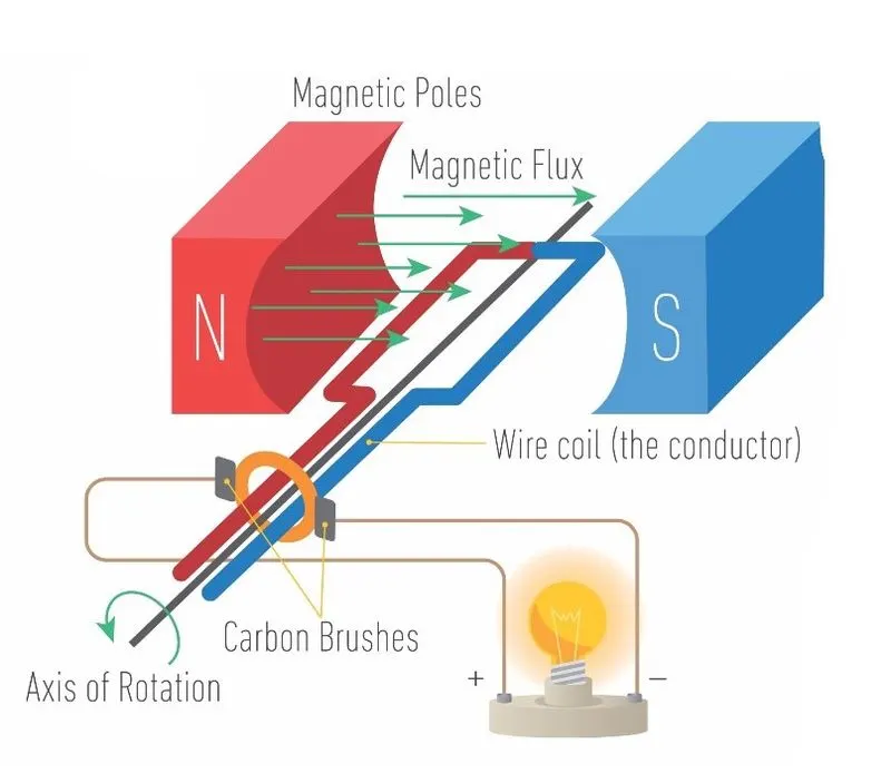
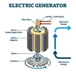
The main components of a overall electric generator are: Engine, Alternator, Fuel System, Voltage Regulator, Cooling and Exhaust Systems, Lubrication Systems, Battery Charger, Control Panel, Main Assembly/Frame.
3. If the total load is 10A from battery, what should be the fuse rating?
Fuse: A fuse is made up of thin strip or strand of metal, whenever the heavy amount of current or an excessive current flow is there in an electrical circuit, the fuse melts and it opens the circuit and disconnects it from the power supply. Fuses are the protectors, these are the safety devices which are used to protect the home appliances like televisions, refrigerators, computers .etc with damage by high voltage.
Fuse rating:
Fuse rating will be calculated based on the Power and Voltage the load works.
Power(watts) = Voltage(v) x Current(A)
Here the total load uses 10 A, generally fuse rating will more than the maximum current used by the load
So, we take the fuse rating as 13-15A fuse.
4. If 500W is the load, what is the voltage and capacity of battery you recommend?
Given: Power =500W, Battery Voltage to be taken as 12V
Assuming the given load is required to run the system for 3 hours at 12V, then
Energy, E = Power x Time
= 500 x 3
= 1500Wh
Using Ohm's law, we know that P=VI
Now, Energy (E)= Power x Time
= V x I x t
Therefore, amp hours are measure of electric charge Q.
So, Energy (E)= V x Q
Q= E/V
Now inserting the values of E & V, we get
Q= 1500/12
= 125Ah
Battery capacity need for this operation is 125Ah and we have a standard battery of 150Ah
So, the recommended voltage and battery capacity is 12V 150Ah.
5. Identify any two elements which are connected parallel to each other. Why they are connected in parallel?
The two elements which are connected parallel to each other are: Horn button with Horns & Light switches with Lights.
Horn button with Horns & Light switches with Lights are connected in parallel because they recieve the same voltages but in different current values.
6. Identify any two elements which are connected in series. Why they are connected in series?
The two elements which are connected series to each other are: Battery and Ammeter & Battery and Starter.
Battery and Ammeter & Battery and Starter are connected in series because ammeter measures the current flowing from the battery, whereas starter need direct current from the battery, since generally current is same in series.
Conclusion:
The Practical Automotive Wiring Circuit Diagram is studied and analyzed.