week-11 Joint creation and Demonstration
AIM:
The objective of the report is to create spherical, revolute, translational and cylindrical types of joints between two rigid bodies and two deformable bodies in Ls-Dyna.
MECHANICAL JOINTS:
A mechanical joint is used to connect one or more mechanical parts(links) to another. Most mechanical joints are used to allow relative movement between the connected parts(links) by constraining some movements.
Types of mechanical joints -
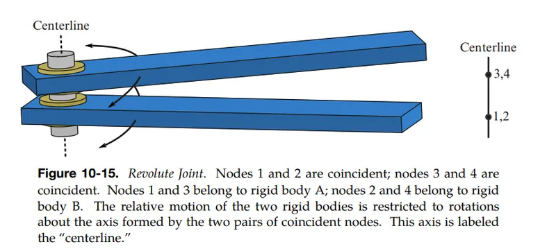
1) Revolute joint -
A revolute joint is a 1 DOF kinematic pair. It constrains the motion of two bodies to pure rotation along a common axis. The joint doesn't allow translation, or sliding linear motion.
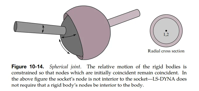
2) Spherical joint -
A Spherical joint is also called as ball-socket joint. It is a 3 DOF kinematic pair allowing rotation along 3 axes.
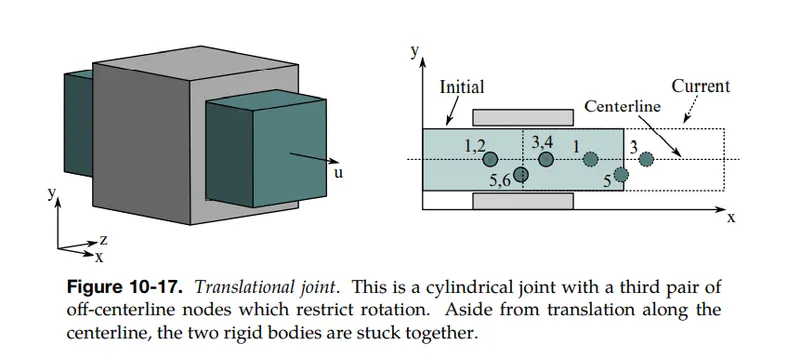
3) Translational joint -
A translational joint is also called as prismatic joint. It is a 1 DOF kinematic pair. It allows translation along the common axis.
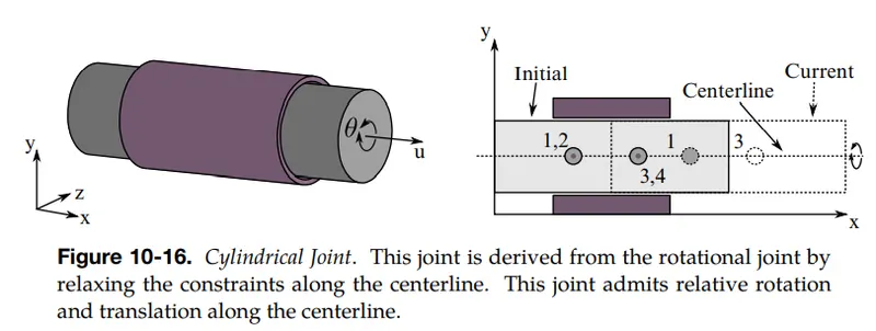
4) Cylindrical joint -
A cylindrical joint is a 2 DOF kinematic pair. Cylindrical joints provide single-axis sliding function as well as a single axis rotation, providing a way for two rigid bodies to translate and rotate freely.
5) Knuckle joint -
A Knuckle joint is a 1 DOF kinematic pair. A knuckle joint is used to connect the two rods which are under tensile load when there is a requirement of a small amount of flexibility or when angular movement is necessary. There is always axial or linear line of action of load.
6) Screw joint -
A Screw joint is a 1 DOF kinematic pair. Screw joints provide single-axis translation by utilizing the threads of the threaded rod to provide such translation. This type of joint is used primarily on most types of linear actuators and certain types of cartesian robots.
7) Universal joint -
A Universal joint is a 2 DOF kinematic pair. A universal joint is a connection between two objects, typically shafts, that allows relative rotation in two axes.
PROCEDURE:
In Ls-Dyna, different types of joints are modeled. In this report, joints are made between two rigid bodies and two deformable bodies.
1) Revolute joint (Rigid body) -
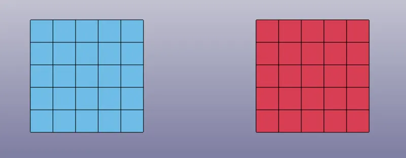
Create two plates of dimension (20x20)as shown in the fig
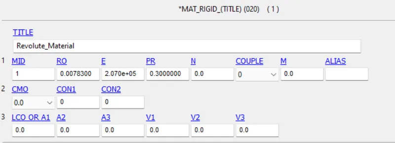
Create rigid material card
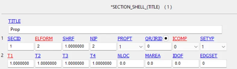
Section shell keycard, of plate thickness 1mm
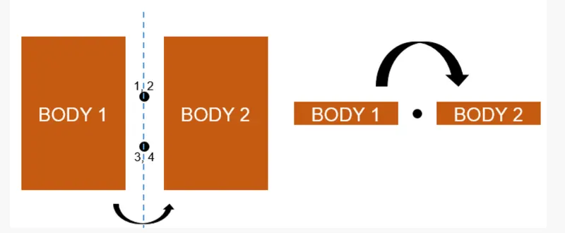
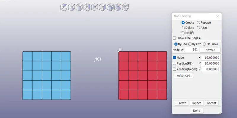
To create revolute joint, for each body two nodes are created. In the following fig, nodes 1,3 represents nodes for body 1 and nodes 2,4 represents nodes for body2. Node 1 coincides with node 2 and node 3 coincides with node 4. The line passing trough these 4 nodes represents axis of rotation.
Create nodes by ELEMENT TOOLS -> NODE EDITING as shown in the fig. Similary create 3 more nodes.
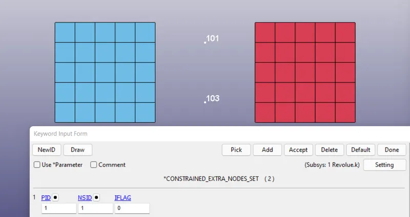
Include the created nodes 101, 103 in PID 1 and nodes 102, 104 in PID 2 by using CONSTRAINED_EXTRA_NODE_SET keycard
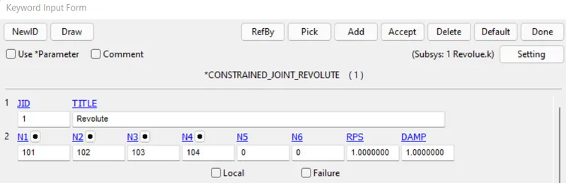
A CONSTRAINED_JOINT_REVOLUTE keycard is used to create a revolute joint.
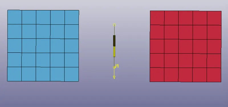
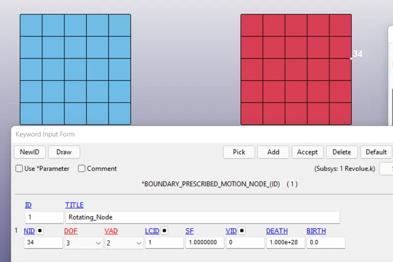
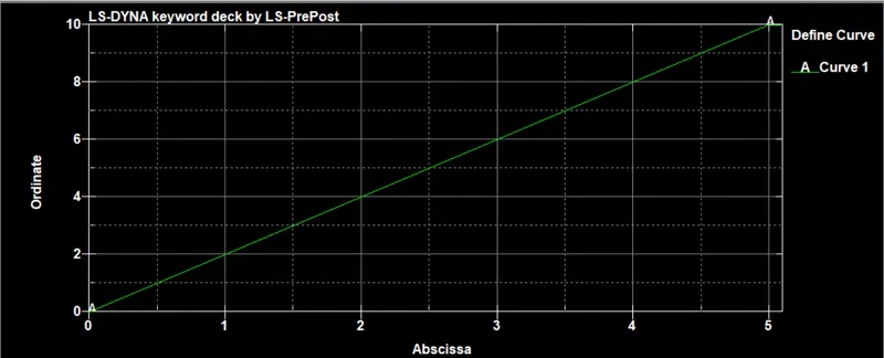
Initial conditions are given to node 34 in the form of displacement curve as shown in the fig.
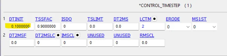
Initial time step is given as 0.1
Simulation -
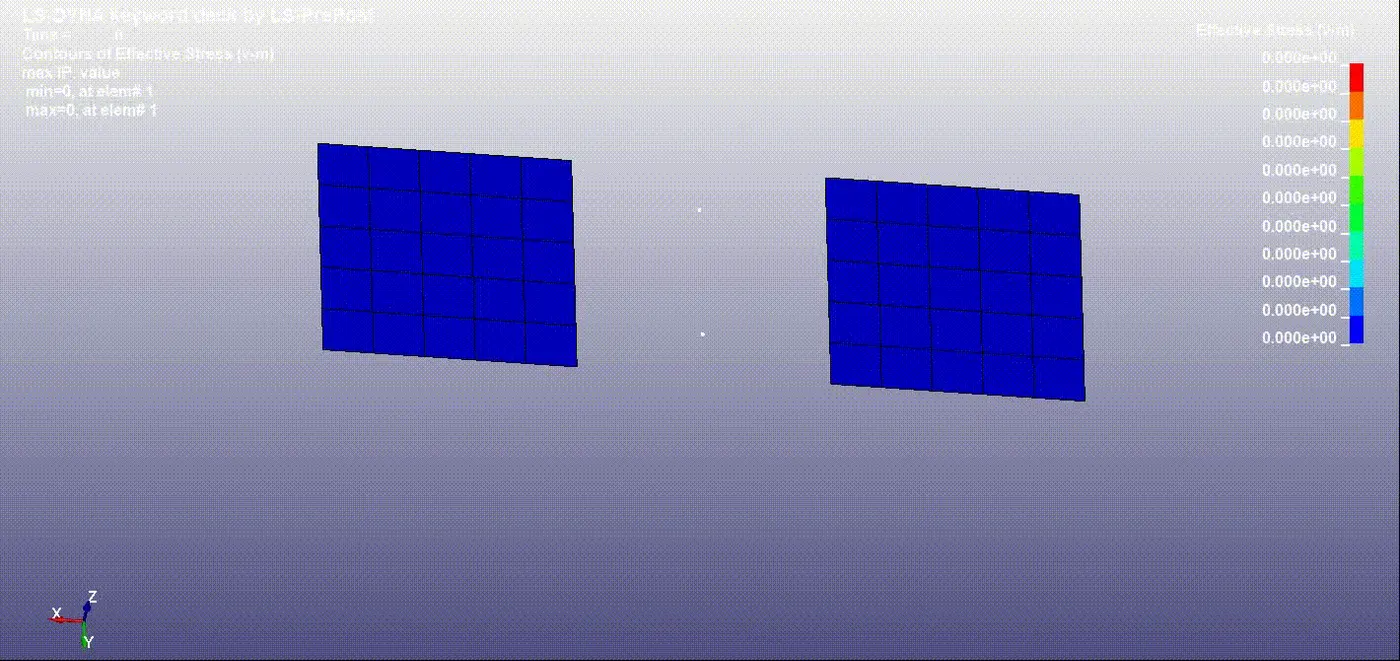
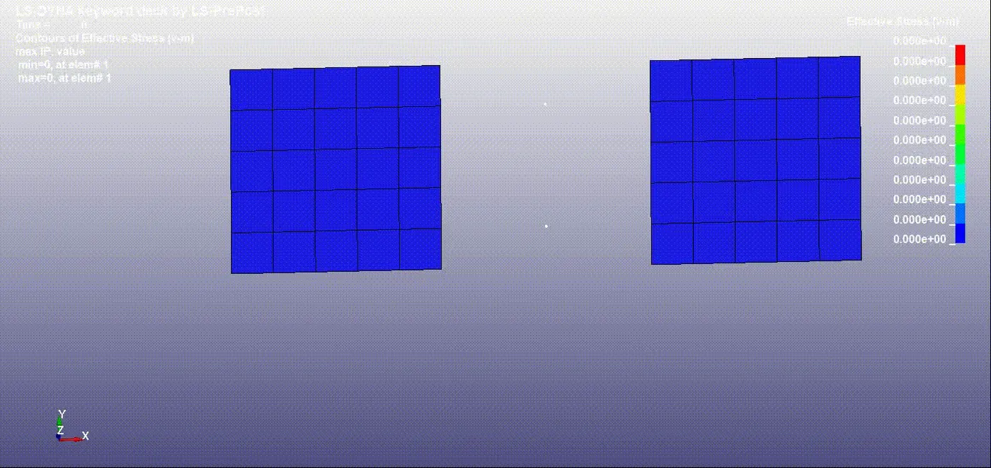
Since, rigid materials are defined, no effective stress is generated.
2) Revolute joint (Deformable-body) -
Create two plates of dimension (20x20)as shown in the fig
Create Elastic material card
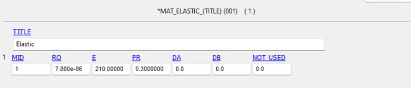
Section shell keycard, of plate thickness 1mm
To create revolute joint, for each body two nodes are created. In the following fig, nodes 1,3 represents nodes for body 1 and nodes 2,4 represents nodes for body2. Node 1 coincides with node 2 and node 3 coincides with node 4. The line passing trough these 4 nodes represents axis of rotation.
Create nodes by ELEMENT TOOLS -> NODE EDITING as shown in the fig. Similary create 3 more nodes.
Create master nodes using CONSTRAINED_NODAL_RIGID_BODY keycard.
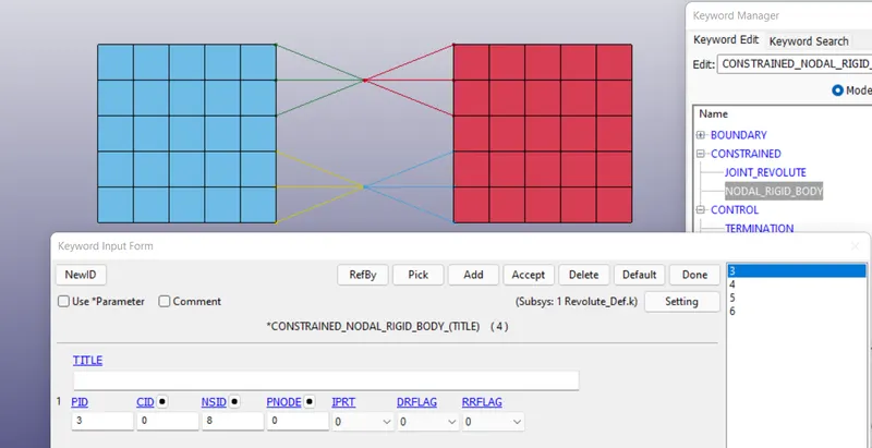
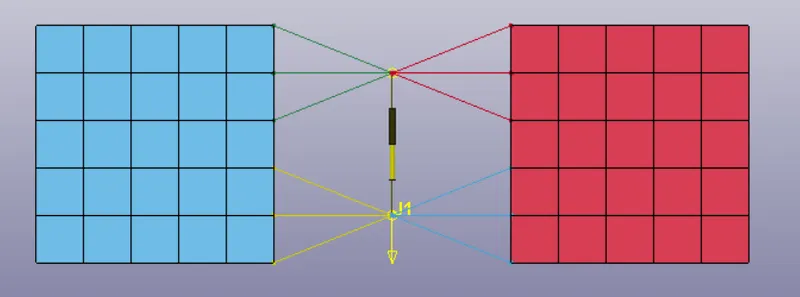
A CONSTRAINED_JOINT_REVOLUTE keycard is used to create a revolute joint.
Initial conditions are given to node 34 in the form of displacement curve as shown in the fig.
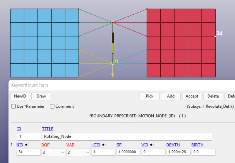
Initial time step is given as 0.1
Simulation -
Since, elastic materials are defined, effective stress is generated.
3) Spherical joint (Rigid body) -
In spherical joint, one node is created for each part at the center of the sphere
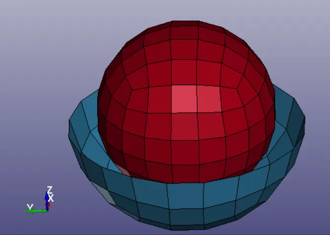
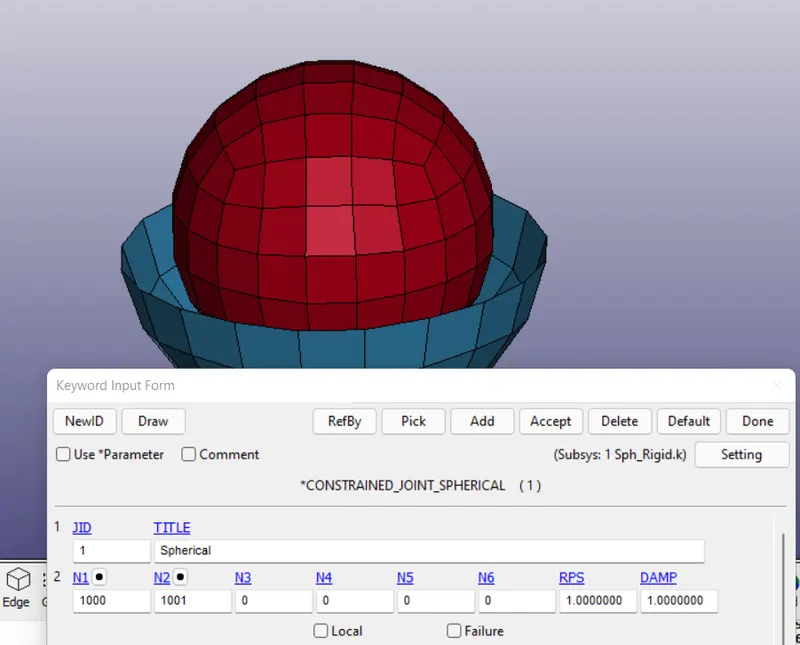
CONSTRAINED_JOINT_SPHERICAL keycard is used to create a spherical joint.
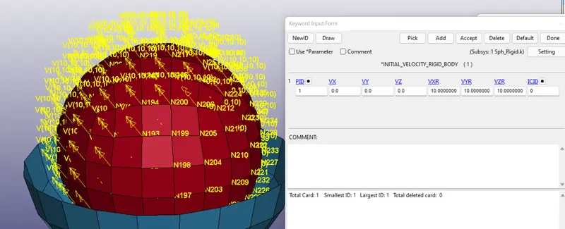
Initial conditions are given as rotational velocity to PID - 1
Simulation -
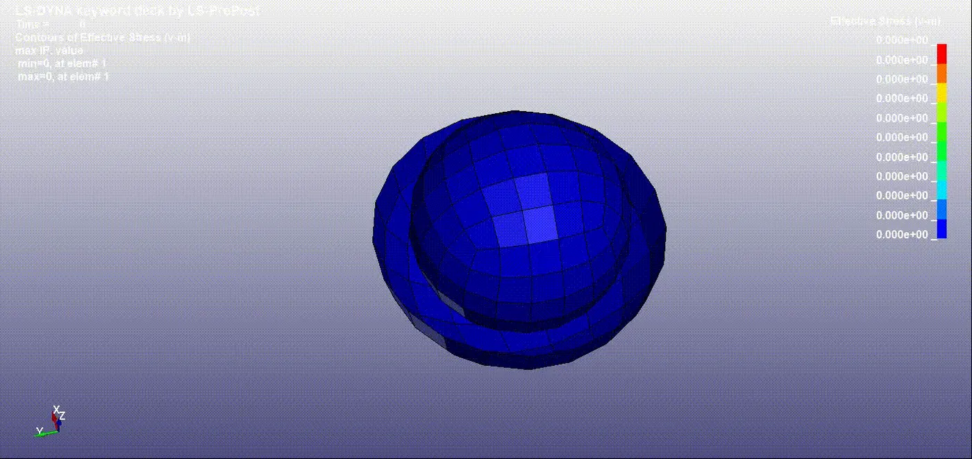
4) Spherical joint (Deformable body) -
Create master nodes using CONSTRAINED_NODAL_RIGID_BODY keycard.
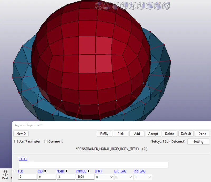
A CONSTRAINED_JOINT_SPHERICAL keycard is used to create a spherical joint.
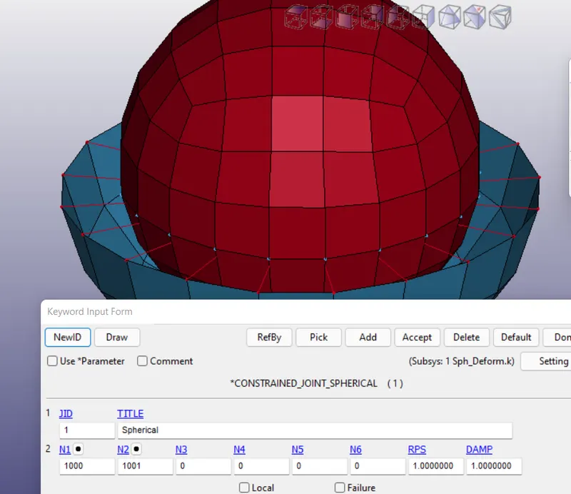
Initial conditions are given as rotational velocity to PID - 1
Simulation -
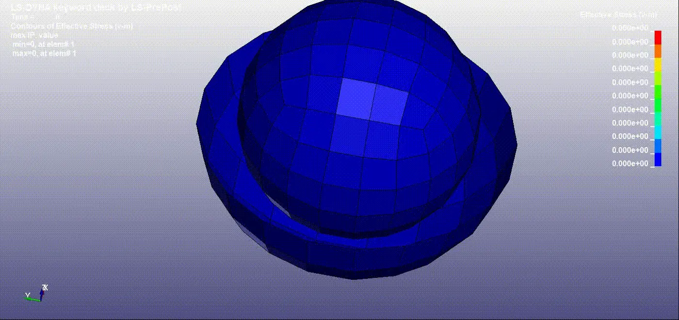
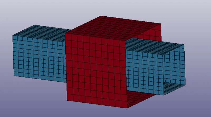
5) Translational joint (Rigid body) -
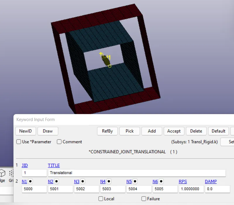
In translational joint, 3 nodes are created for each part
CONSTRAINED_JOINT_TRANSLATIONAL keycard is used to create a translational joint.
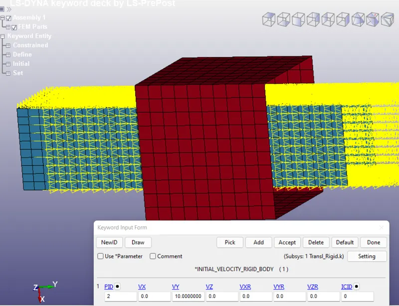
Initial conditions are given as translational velocity to PID - 2
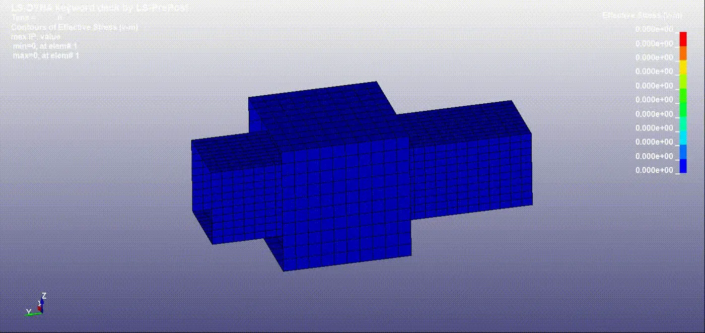
Simulation -
6) Translational joint (Deformable body) -
Create master nodes using CONSTRAINED_NODAL_RIGID_BODY keycard.
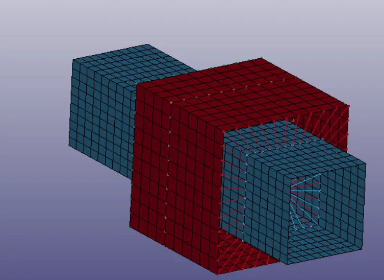
A CONSTRAINED_JOINT_TRANSLATIONAL keycard is used to create a translational joint.
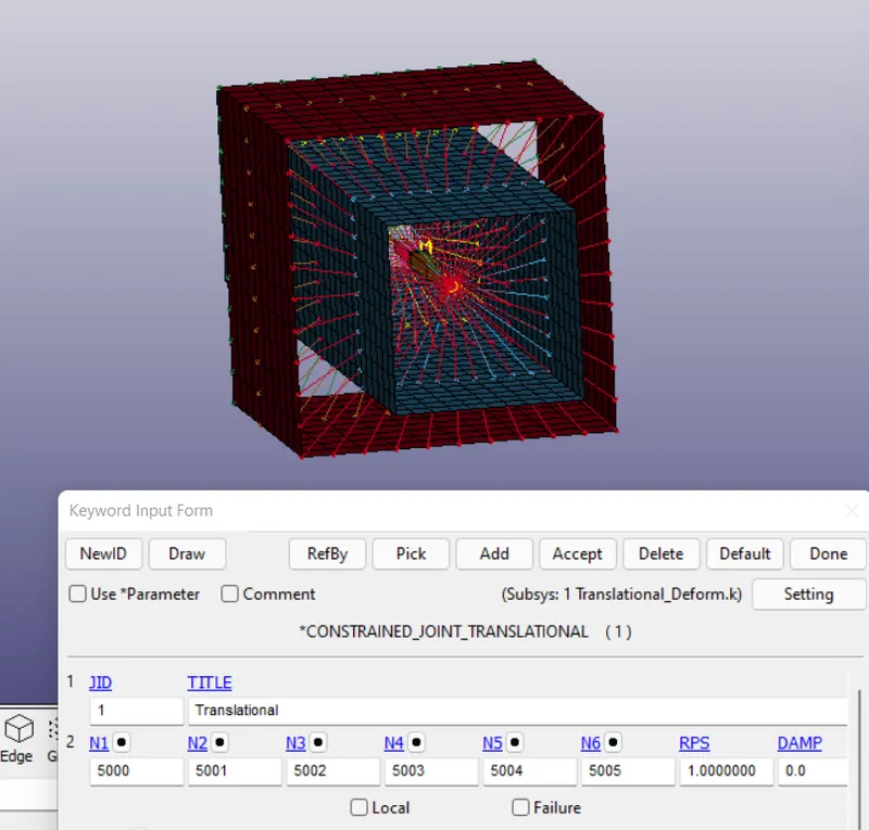
Simulation -
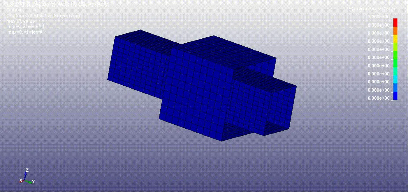
7) Cylindrical joint (Rigid body) -
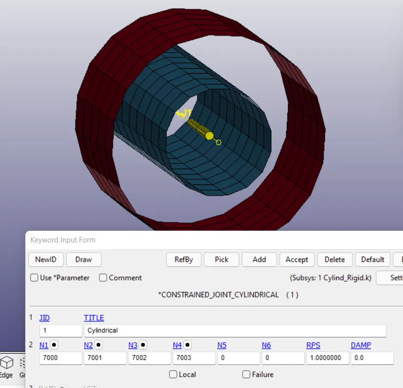
In cylindrical joint, 2 nodes are created for each part
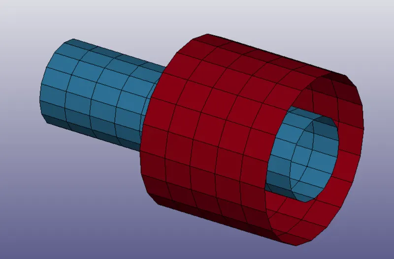
CONSTRAINED_JOINT_CYLINDRICAL keycard is used to create a cylindrical joint.
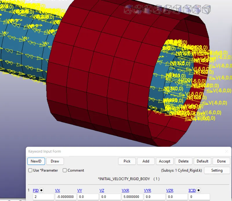
Initial conditions are given as translational,rotational velocity to PID - 2
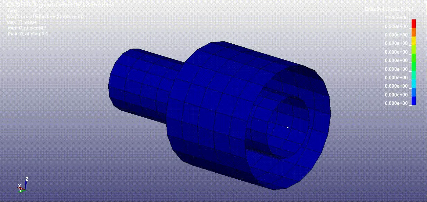
Simulation -
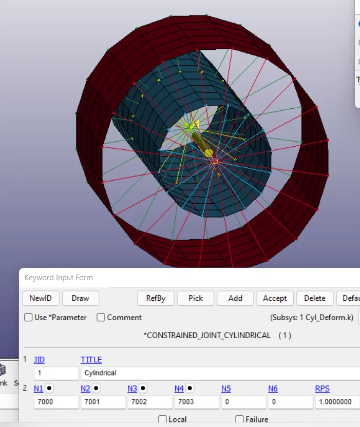
8) Cylindrical joint (Deformable body) -
Create master nodes using CONSTRAINED_NODAL_RIGID_BODY keycard.
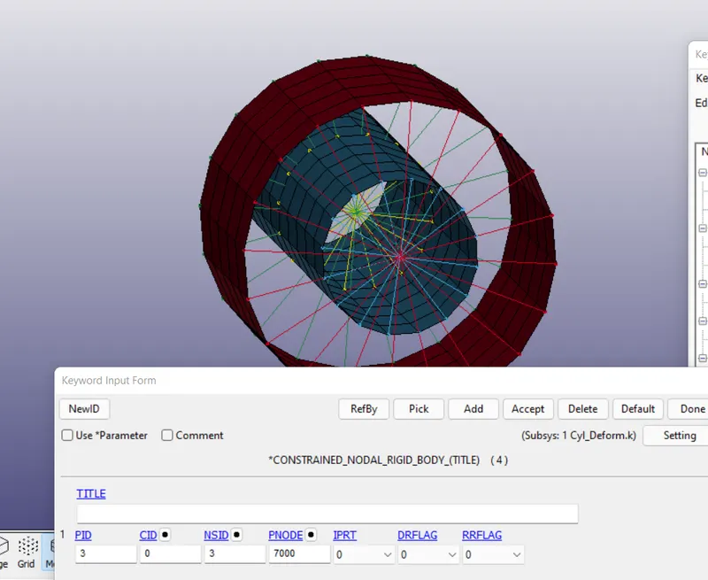
A CONSTRAINED_JOINT_CYLINDRICAL keycard is used to create a cylindrical joint.
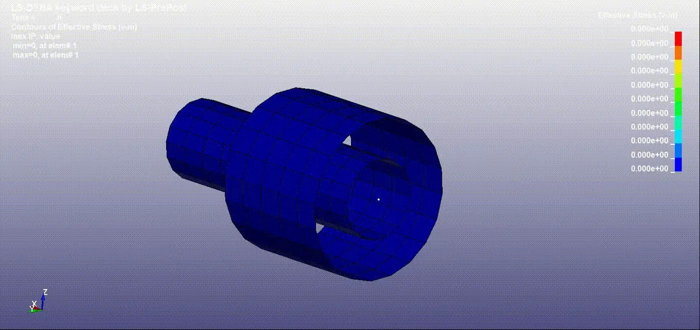
Simulation -
CONCLUSION:
Different types of joints like spherical, revolute, translational and cylindrical types of joints between two rigid bodies and two deformable bodies are demonstrated using Ls-Dyna.