Bird Strike - Project - 2
AIM:
The objective of the report is to simulation of bird strike in aero engine model in LS-DYNA and validate the results. The bird strike model is a classic nonlinear transient dynamics problem similar to car crash and mobile drop. While accurate modeling of the problem requires advanced techniques such as SPH, this problem can be solved using generic explicit solver.
ABSTRACT:
Bird strike to aero-engine can lead to severe damage of air crafts. The bird may strike different parts of the air crafts such as windshield, engine blades, wings etc and it leads to catastrophic failure of components results in emergency landing of air crafts. In olden days, physical modelling are done by using real birds and aircraft components which is expensive. So, in order to minimize the cost and to make modelling easier, several Computational modelling methods have been implemented to perform structural analysis by using FEA. So, by validating the results, design changes are made to aircraft. In this model, the simulation is done for the bird strike to the aero-engine in LS-DYNA.
Requirements to large models simulation -
- The bird, casing, and the blades should be in different input files and there should be one main file referencing all the input files.
- The main file should contain only references. Control cards and boundary conditions should be there in another separate file. The reference include path should be such that the folder can be copied anywhere and it is able to correctly reference all the file and run the simulation.
-
Follow a consistent numbering approach 100000+ for nodes, 500000+ for elements, and 1000+ for the parts. All other keywords should be numbered within 10000-19999 while following a range for each one.
-
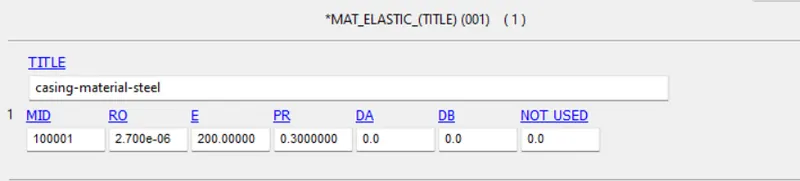
The blades should rotate at a constant velocity but the casing should remain stationary. The cylindrical bird model should travel along its own axis and hit the blades. Use elastic material for the bird(2000MPa) and the casing(200GPa). The material model for the blades is attached. The velocity of the engine blades and the birds can be chosen so that blade failure can be seen within a short span of time.
PROCEDURE:
Different parts have to be made in seperate input files.
NOTE - Unit system - Kg-mm-ms
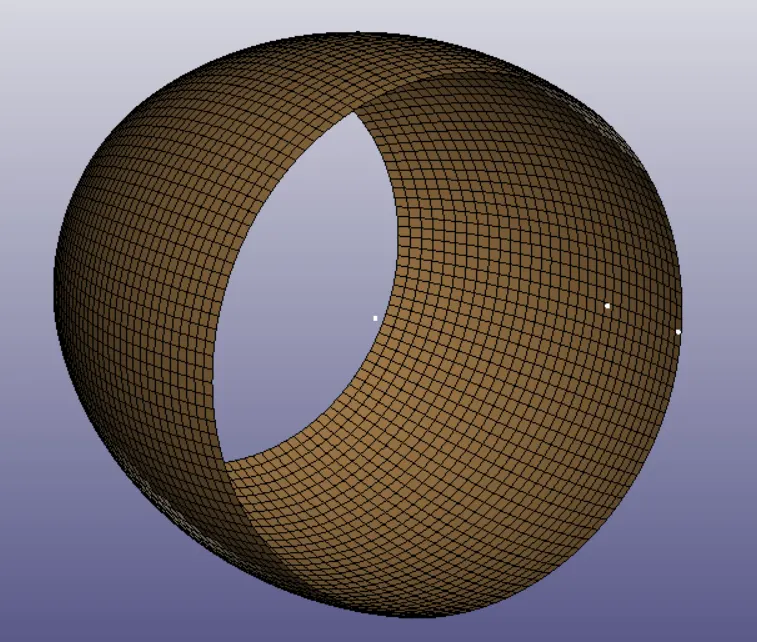
1)Engine casing-
Material card -
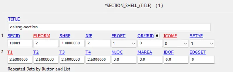
Section card -
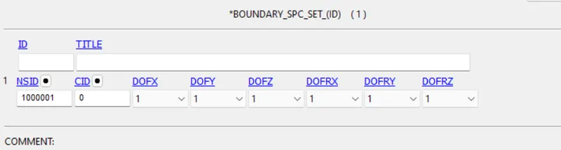
Boundary card -
Since, the engine casing is fixed, it should be constrained in all directions.
2)Engine blades-
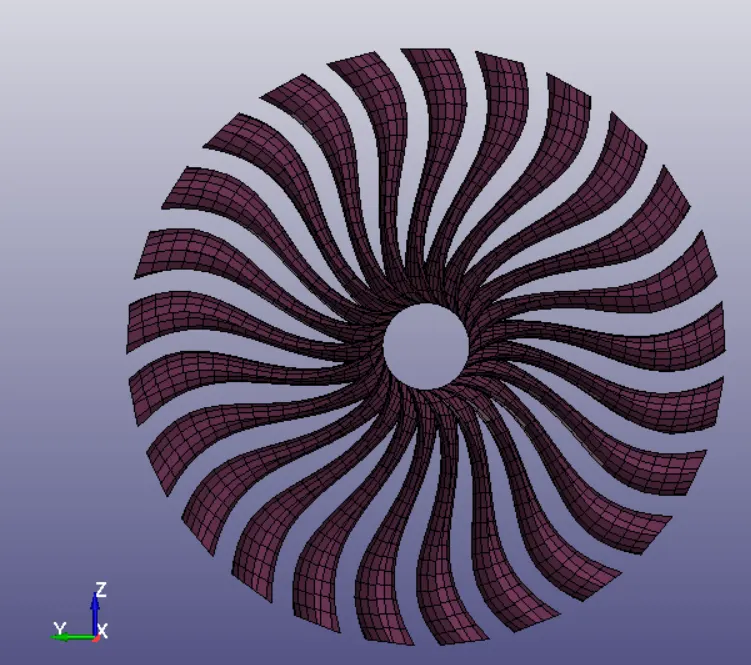
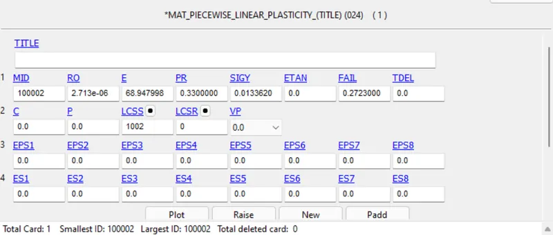
Material Card -
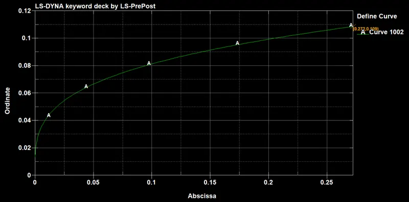
The engine blades material card is to be modelled with the following curve
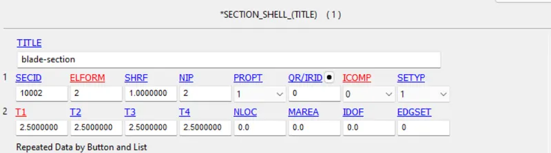
Section card -
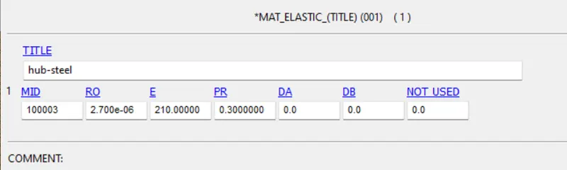
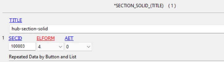
3)Hub -
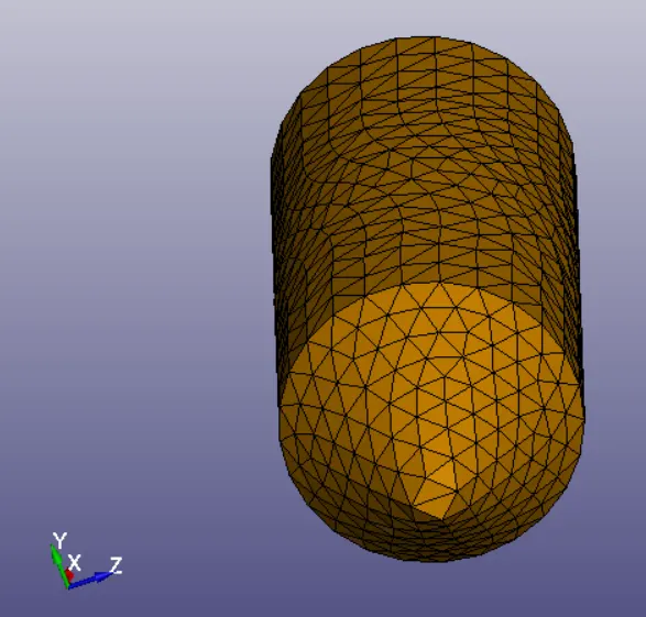
Material card -
Section card -
4)Bird -
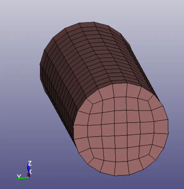
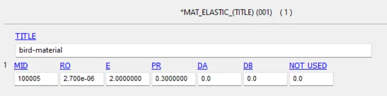
Material card -
Section card -
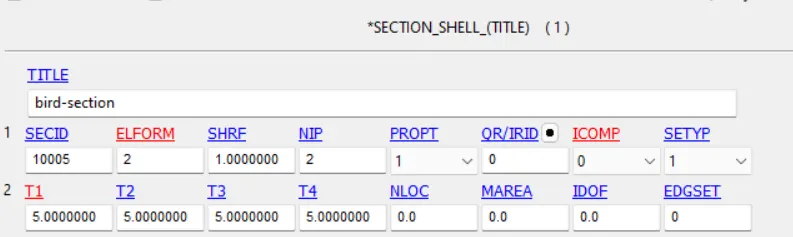
Similarly, create all the necessary keycards in another input file and include all these file in a main file.
Contact card -
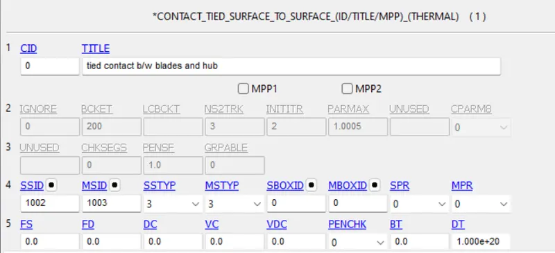
The blades should rotate along with the hub, so tie contact keycard is created by considering hub as master and blades as slave.
The bird after striking the blades, the bird should not penetrate the blades and engine casing, the blades should not penetrate engine casing. So, three automatic surface to surface contact keycards are created.
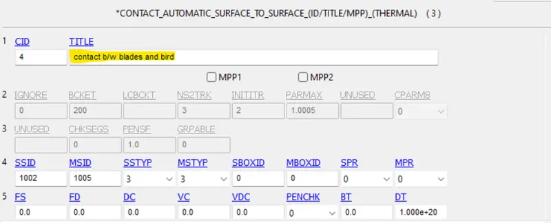
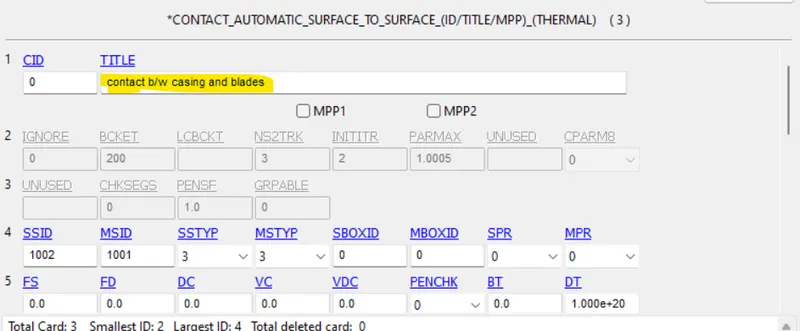
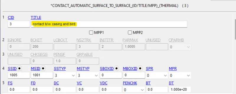
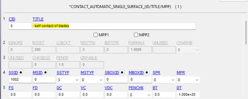
The blades sholud not penetrate to each other. So, single contact surface is created for blades.
Initial conditions -
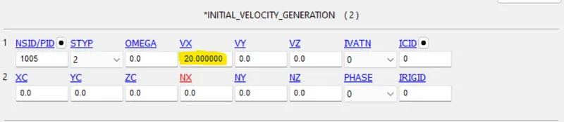
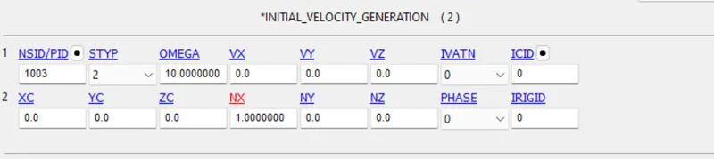
The bird is moving with a velocity of 20mm/ms along x-axis and hits the engine blades.
The Hub is rotaing along its axis
Database keycard-
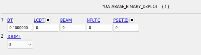
The time step dt is set as 0.1ms
Control keycard -
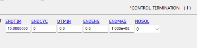
The total termination time is set around 10ms.
Post-Processing -
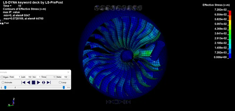
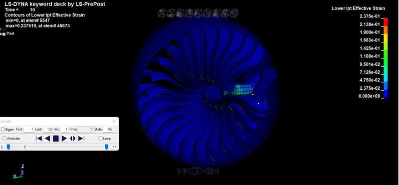
The simulation has been done and the results are validated in the post-processing unit.
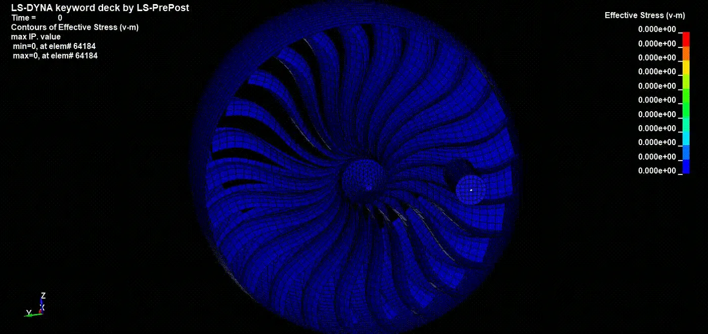
Max-effective stress = 0.0762 Kg/mm-ms2 at t = 10ms
Max-effective strain = 0.2375 mm/mm at t = 10ms
Energy plot
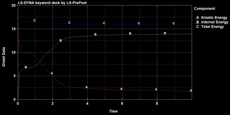
It is observed from the plot, the total energy is constant, which indicates the system is stable. Due to collision, the kinetic energy of the system decreases and internal energy increases.
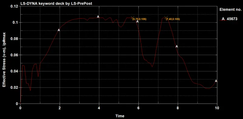
The following fig shows the Effective stress for the element 45673 which is on the blade. The max effective stress is 0.106 Kg/mm-ms2. The stress induced before the collision is due to circumferential stress. From the plot, it is observed that contact occurs between blades and bird till 5.7ms.
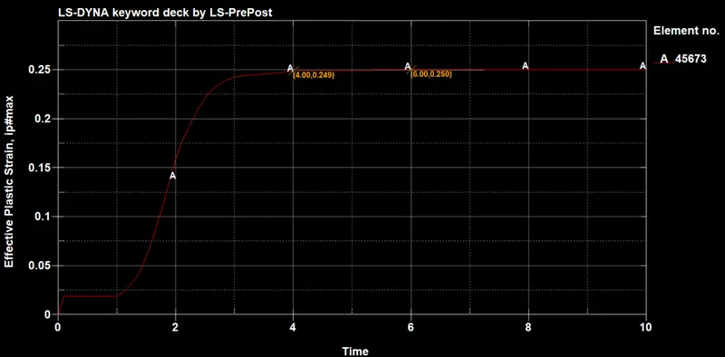
The following fig shows the effective plastic strain for the element 45673 which is on the blade. The max effective plastic strain is 0.25 mm/mm.
CONCLUSION:
The simulation is performed and structural analysis on engine blades is done. The maximum effective stress induced in the blades is less than the failure stress. Since the blades undergo plastic deformation, there will be failure in the air craft engine.