Week 3 - 2D meshing for sheet metal
AIM :
To mesh the given hood cad model by following these quality criteria.
S.NO Quality Criteria Value
1 Target length 5
2 Minimum length 2
3 Maximum length 7
4 Aspect 3
5 Warpage 15
6 Skewness 45
7 Jacobian 0.7
8 Minimum Quad Angle 45
9 Maximum Quad Angle 135
10 Minimum Tria Angle 30
11 Maximum Tria Angle 120
12 Tria Percentage 15
PROCEDURE :
In order to mesh the given hood cad model, certain steps should be followed So that better quality mesh is achieved.
First import the cad geometry in the ANSA or any pre-processing software. After importing the geometry there may be a chance of occurring new topological errors, So topo function is to be performed after importing the geometry. This was performed by FACES > TOPO. Next, the cad model orientation issues must be checked by FACES > ORIENT. The entire cad model will be represented in grey and yellow colors in ENT mode.
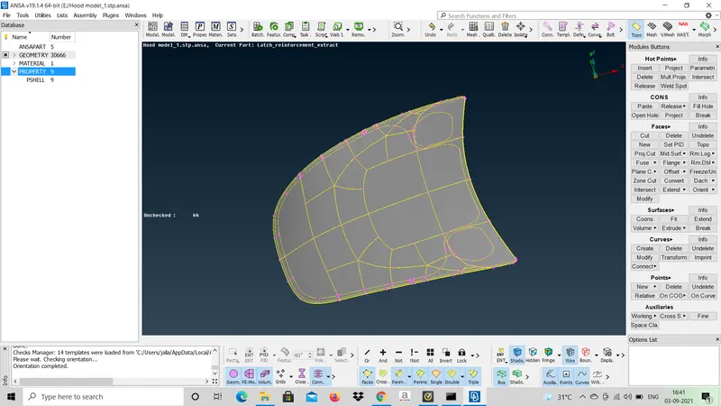
FIG 1 - Orientation of cad model
After this topological errors must be checked before performing meshing so that accurate results were obtained. This was done by CHECKS MANAGER > GEOMETRY > EXECUTE. The checks manager will show the errors that were present in the cad model. ANSA will provide the option of solving these errors either manually or automatically.
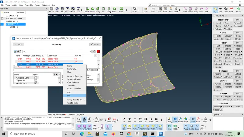
FIG 2 - Topological errors of cad model
In the fig2 by selecting the fix option, the topological errors were automatically fixed. Some of these errors cannot be automatically fixed, they have to be performed manually. The meshing can be performed in 2D as well as in 3D. 3D meshing is time consuming process as it takes lot of of time to compute the model where as 2D meshing is performed for those models where thickness of components is less than 5mm. For 2D meshing mid surface must be extracted for the cad model and meshing is performed which gives similar result as of 3D meshing. Next the thickness of the cad model is measured by MEASURE command, as the thickness of model components are 0.75mm and 1.2mm midsurface extraction is done to perform 2D meshing. In ANSA the mid surface extraction can be done either manually or automatically. Manual mid surface extraction was done by FACES > OFFSET command and faces must be selected and offset distance must be given and after extracting the surface new property ID must be assigned to the surface by FACES > SET PID.
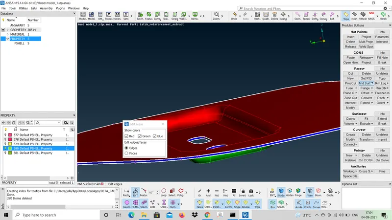
FIG 3 - Mid surface extraction
In the fig 3, automatic midsurface extraction is performed. This was performed by FACES > MID SURFACE > SKIN and entire geometry to be selected and next faces of the geometry were shown in red and green color and thickness in blue color and by pressing the middle mouse button mid surface is extracted and ANSA will automatically set a new property ID to the extracted surface. But the parent geometry is deleted in this process, the parent model can be recovered by FACES > UNDELETE. Next after extracting mid surfaces, swift to the mesh module from the topo module to create mesh elements. In mesh module all the cons are shown in green color, hot points in white dots and pink dots indicate perimeter elemental structures. The distance between the perimeter elemental to be assigned to 5mm, this was done by PERIMETERS > LENGTH and select the entire geometry and assign the value of 5mm. Due to presence of complexities in the geometry, flexibility must be given to the mesh elements which is called criteria range. Next open the quality criteria index by F11 key and assign the criteria ranges to the mesh elements as shown in the fig 4.
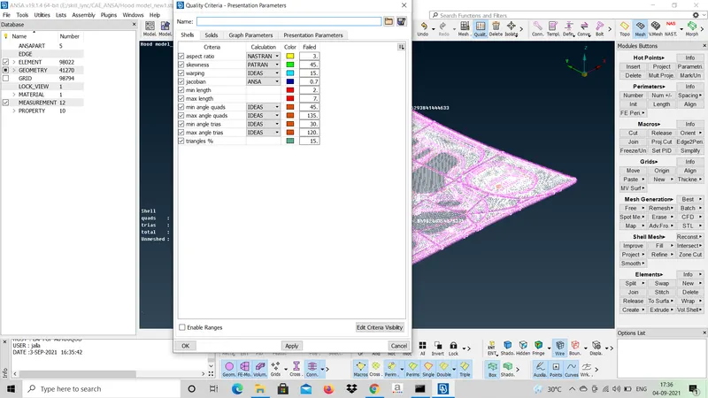
FIG 4 - Quality criteria index
After defining the ranges for the quality aspects, select PRESENTATION PARAMETERS and enable ELEMENTS % and select DETAILS ON DEMAND EFFECT to ALL DETAILS.
Before meshing the cad model, check the element perimeter length by using MEASURE command. Check for the areas where element length may try to fail the given criteria like fillets, sharp curves and corners etc and defeaturing to be done for those areas.
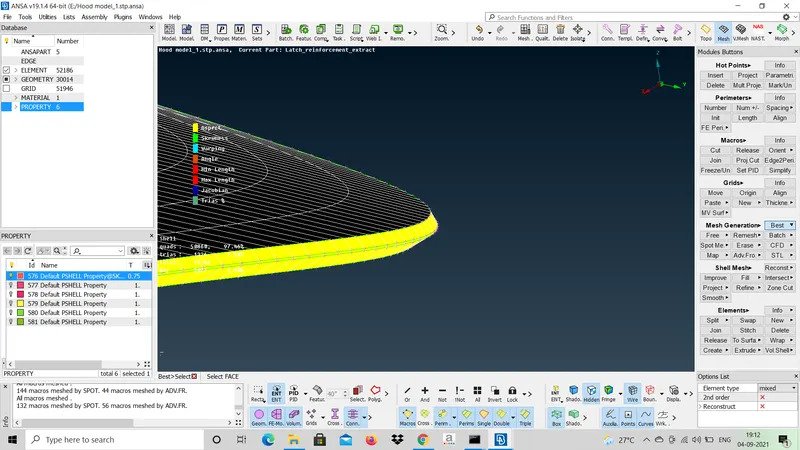
FIG 5 - Before defeaturing the geometry
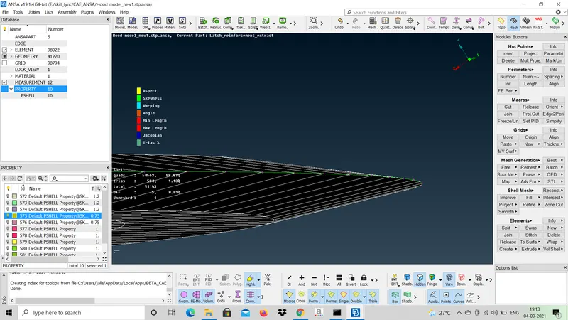
FIG 6 - After defeaturing the geometry
Defeaturing means compromising on one of the feature to save another feature. Fig 5 shows the area where elements will not satisfy quality criteria, So the top and bottom double cons are suppressed so that the elements satisfy quality criteria which is shown in Fig 6. Next keep the number of edges as even on the perimeter of the holes and align the edges of holes parallel to the surround entities by PERIMETERS > SLIDE command and mark the hot points by HOT POINTS > MARK. Next mesh the cad model by MESH GENERATION > BEST and select the surfaces that needs to be meshed. After mesh is generated go to hidden mode to identify the elements that fails to satisfy quality criteria. ANSA will try to minimize the number of elements that fails to satisy the quality criteria by rearranging the mesh by SHELL MESH > RECONSTRUCT.
Some of these types of patterns should be avoided so that better mesh flow is generated and accurate results were obtained-
1) Tria elements on the perimeter of the geometry.
2)Back to back trias.
3)Two trias pointing towards each other.
4)Two trias facing opposite to each other.
5)Rotating quads.
The above patterns can be avoided by ELEMENTS > SPLIT, SWAP and JOIN commands.
LEARNING OUTCOMES :
1) Fixing the topological issues manually like triple cons, needle faces, unchecked faces, cracks and collapsed cons.
2) Extracting the midsurface both manually and automatically.
3) Manually rearranging the unnecessary patterns like back to back trias, rotating quads etc.
4) Bring the tria elements away from the curvature to plane surface and try to eliminate them.
5) Creating middle curve between two set of cons and curves.
CONCLUSION :
Pre processing the cad model is one of the important task that needs to be done so that accurate results can be achieved by generating the better mesh flow. So using preprocessing software like ANSA, HYPER MESH etc and by following certain set of guide lines better mesh flow is achieved which gives better results.