Week 6 - Creating connection for Rear door
AIM:
To create suitable connections for the given rear door cad model.
PROCEDURE:
After performing meshing for the cad model, the next step is to make all the available connections. Depends on the type of application, the suitable deck to be selected and connections to be made. For durability analysis Abacus solver deck is to be selected, for NVH analysis Nastran solver deck is to be selected, for safety analysis LS Dyna solver deck is to be selected. The given cad model is rear door model and NVH analysis has to be done to the model, so connections to be made based on the Nastran solver deck.
The PID's should be allocated to the respective parts. The rigid bolt connection can be captured either manually or automatically. The manual connection has to be made with ELEMENTS > RBE2 > MANY NODES and select all the nodes of the rigid joint. For automated bolt connection, first COG for the respective hole has to be made by TOPO MODULE > POINTS > ON COG. Next covert this 3D point to bolt by ASSEMBLY >CONVERT > 3D POINT and connection has to be made by ASSEMBLY > CONNECTION MANAGER . Fig 1 shows the bolt connection.
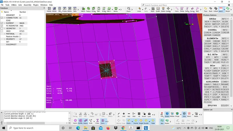
FIG 1: BOLT CONNECTION
Next for door hinge connection the rigid connection has to be done, as the door rotates along the hinge the DOF should not be constrained along z - direction. This was done done by ELEMENTS > INFO and select the stem of the joint and input 12345 in CM, fig 2 shows the RBE2 card of the rigid joint.
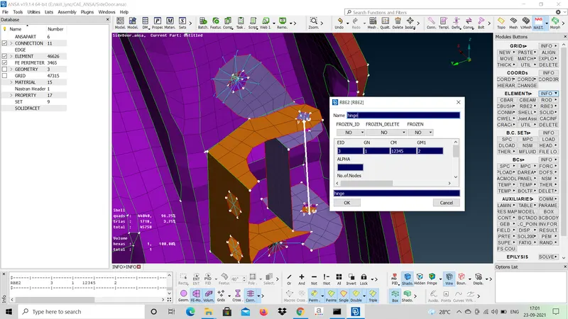
FIG 2: HINGE JOINT OF DOOR
Next the door handle of the car door is captured by its COM. Fig 2 shows the capturing of the car handle, first make RBE2 connections for the holes and create a master node in between these holes. The COM is applied by ELEMENTS > CONMi > CONM2 > NODES and select the master node which is present in between two RBE2 joints and the mass of the handle has to be input in metric tonne units.
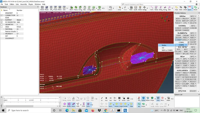
FIG 3: CAR DOOR HANDLE
Next for rail mechanism in door spot weld connection has to be made. This was done by creating a 3D point on the part shown in the fig 4 and convert this 3D point to spot weld point and in the connection manager RBE3 HEXA RBE3 representation has to be made.
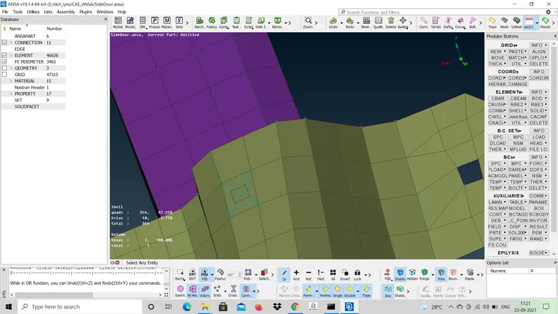
FIG 4: SPOT WELD CONNECTION
The glass present in the door is surrounded by rubber strips which acts as springs and dampers, so these are captured by using CBUSH connection. So first create a curve around the glass by MESH MODULE > PERIMETERS > FEAT2CURVE and next convert this curve to SPOT LINE and in the connection manager RBE3-CBUSH-RBE3 has to be selected and in the bush Property ID 6 stiffness coefficients values have to be input for the bush as shown in fig5
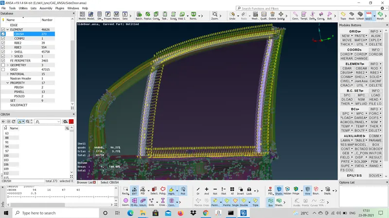
FIG 5: CBUSH CONNECTION
Next after CBush connection is made make sure that the orientation of all the CBush connections must be alligned with the global co-ordinate system so that better results were obtained. This was done by opening the CBUSH card as shown in fig 6 and change the ORIENT to WITH CORD and CID to 0 so that global co-ordinate system orientation is assigned to the CBUSH connection.
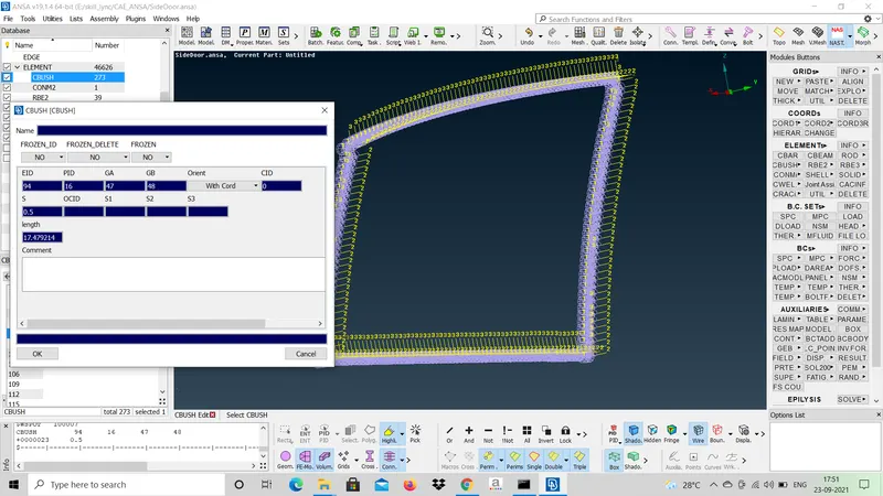
FIG 6: CBUSH CARD
LEARNING OUTCOMES:
- Connection of rigid bolt joint.
- Connection of weld joint.
- Connection of spot weld joint.
- Connection of CBUSH joint.
- Mass model Representation of handle.
CONCLUSION:
The connections were made for the cad model and next simulation has to be performed by applying boundary conditions.