Week- 5 - Solid meshing
AIM:
To perform unstructured solid mesh for the given rearview mirror cad model. For 2D meshing, the given quality criteria should be followed.
S.NO Quality Criteria Value
1 Target length 1
2 Minimum length 0.5
3 Maximum length 2
For 3D meshing, the mentioned quality criteria should be followed.
S.NO Quality Criteria Value
1 Tet collapse 0.2
PROCEDURE:
Solid meshing should be performed to those components whose thickness is greater than 5mm or for those where thickness cannot be measured. In solid meshing there are two types of mesh are followed - 1)Structured mesh 2)Unstructured mesh. For the given cad model unstructured mesh is performed. Among these two patterns structured mesh gives accurate results but the computational time is very high.
In order to mesh the given Rearview mirror cad model, certain steps should be followed So that better quality mesh is achieved.
First import the cad geometry in the ANSA or any pre-processing software. After importing the geometry there may be a chance of occurring new topological errors, So topo function is to be performed after importing the geometry. This was performed by FACES > TOPO. Next, the cad model orientation issues must be checked by FACES > ORIENT. The entire cad model will be represented in grey and yellow colors in ENT mode.
Fig 1 shows that cross-sectional view of the cad model, as the cad geometry don't have any definite thickness solid meshing is performed to this model.
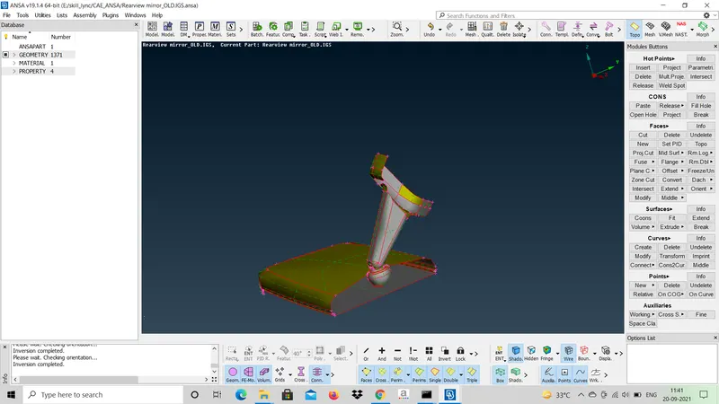
FIG 1 - CROSS-SECTIONAL VIEW OF MODEL
After this topological errors must be checked before performing mesh so that accurate results were obtained. This was done by CHECKS MANAGER > GEOMETRY > EXECUTE. The checks manager will show the errors that were present in the cad model. ANSA will provide the option of solving these errors either manually or automatically.
Next after geometric cleanup, measurement values should be taken so that defeaturing can be performed before meshing. To measure the length go to UTILITIES module > MEASURE.
Fig 2 shows the measured features length don't meet the minimum length criteria, So defeaturing should be done. Fig 3 shows the cuts which are defeatured in order to meet quality criteria.
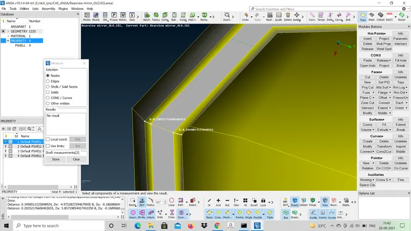
FIG 2 - BEFORE DEFEATURING
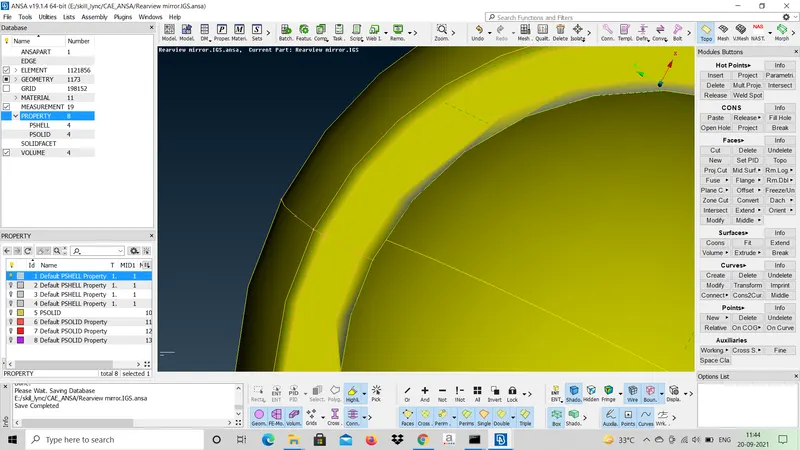
FIG 3 - AFTER DEFEATURING
Next to perform solid meshing, there is no need of extracting the mid surface. Go to the Mesh module and assign the perimeter and macro length to the model. In order to do unstructured meshing, first, mesh the surface of the geometry with tria and ortho tria elements. Trai elements should be meshed on the flat surfaces and for the curved surfaces ortho tria elements should be meshed so that featured are captured perfectly without distortion of the curved surface. In quality criteria dash board, input the quality ranges for both shell and solid models. Next change the element type to either tria or ortho tria elements before performing the spot mesh. After meshing the curved surfaces with ortho tria and flat surfaces with tria elements, next go to VOLUME MESH Module. So in order to perform 3D mesh first define the entire volume as closed volume by VOLUMES > DEFINE > MANUAL and select the entities to assign closed volume. As this closed volume has no definite thickness in PID MODULE no need of assigning the thickness. Next mesh the elements by UNSTRUCTURED MESH > TETRA FEM. The status of meshing can be checked in volumes list as shown in fig 4.
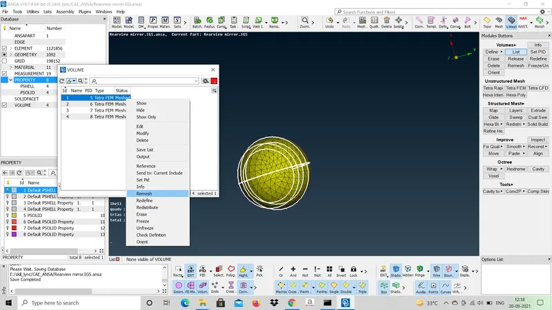
FIG 4 - VOLUME LIST
The volume bounds can be checked by switching off the GEOMETRY and FE - MODE and switching on the BOUNDS.
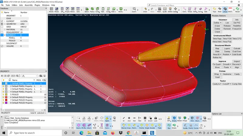
FIG 5 - VOLUME BOUNDS
The computational time for solid mesh is higher when compared to shell mesh as in the fig 6 it is clearly shown that the elements in the 3D mesh is 10 times more compared to shell mesh elements.
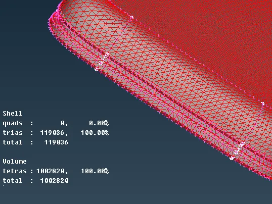
FIG 6 - TOTAL N0.OF ELEMENTS IN SHELL AND SOLID MESH
Next, the volume elements can be released by VOLUMES > RELEASE.
LEARNING OUTCOMES:
- To perform solid mesh.
- Clearing the quality errors in solid mesh elements.
CONCLUSION:
The meshing of the model is done with a total of 1,19,306 shell elements and 10,02,820 solid elements.