Project - 2 - Meshing on the suspension Assembly
AIM:
To perform mesh on the suspension assembly cad model by following quality criteria and apply suitable connections.
PROCEDURE:
In order to mesh the suspension assembly cad model, certain steps should be followed So that better quality mesh is achieved.
First import the cad geometry in the ANSA or any pre-processing software. After importing the cad geometry, the orientation issues must be checked by FACES > ORIENT. The entire cad model will be represented in grey and yellow colors in ENT model as shown in fig 1. Dont use TOPO function unnecessarily as this cad model comprised of many parts and the tolerance of TOPO function is less, unnecessary TRIPLE cons will be formed.
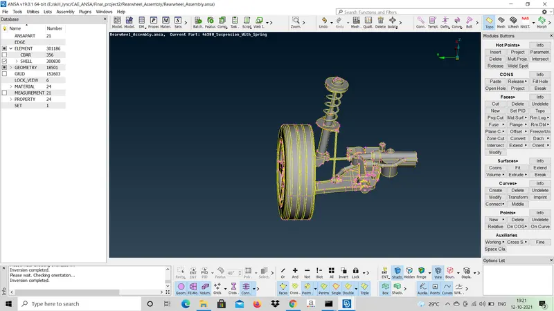
FIG 1 - Orientation of cad model
After this topological errors must be checked before performing meshing so that accurate results were obtained. This was done by CHECKS MANAGER > GEOMETRY > EXECUTE. The checks manager will show the errors that were present in the cad model. ANSA will provide the option of solving these errors either manually or automatically.
Next isolate each part by using INOT > PID REGION, and assign PID to each party by FACES > SET PID.
Next, this cad model comprised of parts which have less than 5mm thickness and greater than 5mm thickness. So 3D mesh is to be performed for parts which have thickness greater than 5mm and 2D mesh is performed for parts which have less than 5mm thickness and extract mid surface by FACES > OFFSET as shown in fig2
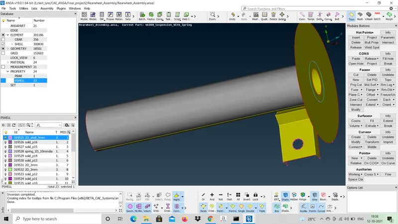
FIG 2 - Mid surface for shell components
Next perform meshing a per the quality criteria for the different components as follows
| S.NO | QUALITY CRITERIA | VALUE |
| 1 | Target length | 4 |
| 2 | Minimum length | 2 |
| 3 | Maximum length | 6 |
| 4 | Aspect | 3 |
| 5 | Warpage | 15 |
| 6 | Skewness | 45 |
| 7 | Jacobian | 0.7 |
| 8 | Min Quad angle | 45 |
| 9 | Max Quad angle | 135 |
| 10 | Min Tria angle | 30 |
| 11 | Miax Tria angle | 120 |
TABLE 1: Quality criteria for thickness less than 5mm
| S.NO | QUALITY CRITERIA | VALUE |
| 1 | Target length | 4 |
| 2 | Minimum length | 2 |
| 3 | Maximum length | 6 |
| 4 | Skewness | 45 |
TABLE 2: Quality criteria for non uniform thickness components
| S.NO | QUALITY CRITERIA | VALUE |
| 1 | Target length | 6.5 |
| 2 | Minimum length | 5 |
| 3 | Maximum length | 10 |
| 4 | Skewness | 45 |
TABLE 3: Quality criteria for Tyre and Rim
| S.NO | QUALITY CRITERIA | VALUE |
| 1 | Tet-collapse | 0.2 |
TABLE 4: Quality criteria for volume meshing
Next after extracting the mid surface for the component, mixed element mesh should be constructed following Table 1 criteria on the surface as shown in fig 3.
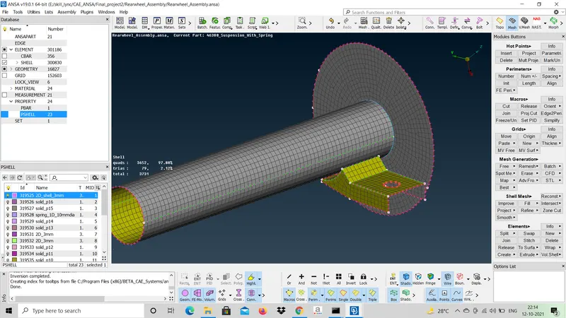
FIG 3 - 2D Mesh
Next for the solid components, mesh should be constructed by following Table 2 quality criteria on the surface as shown in the fig 4.
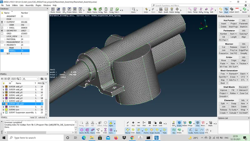
FIG 3 - surface Mesh constructed on the closed volume components of thickness greater than 5mm
It should be noted that for flat surface tria elements should be constructed and for curved faces ortho tria should be constructed so that curved features are captured properly without distortion of the faces.
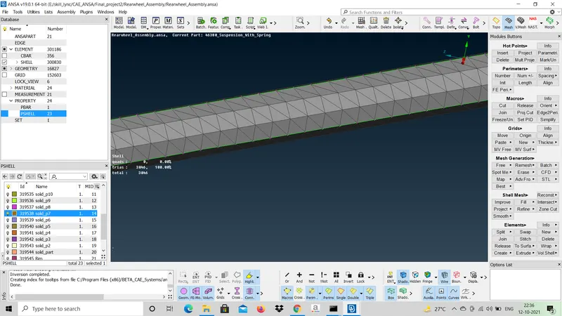
FIG 4 - Ortho tria elements constructed on curved surfaces
Next for the Tyre and Rim solid components, mesh should be constructed by following Table 3 quality criteria on the surface. It is not mandatory to completely remove the off elements. For some narrow features as shown in fig 5, distance between the features is 4mm so the elements in these type of regions will fail that can be ignored as shown in fig 6.
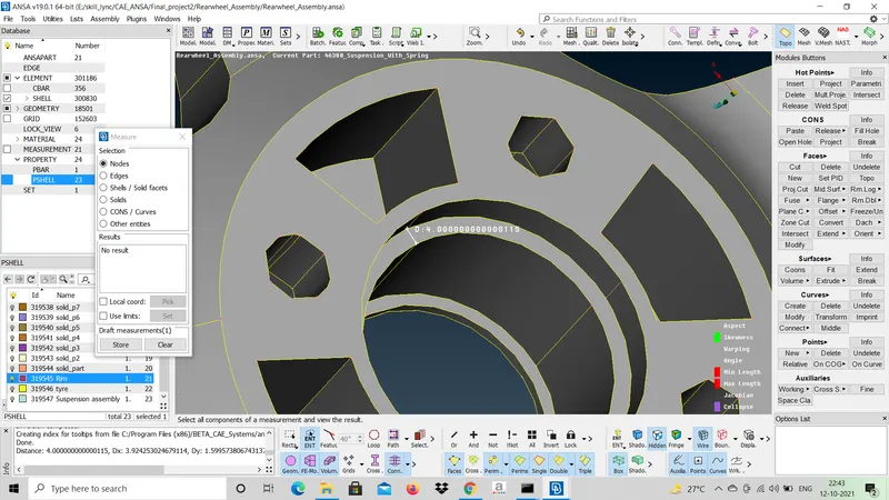
FIG 5 - Narrow features on the Rim part
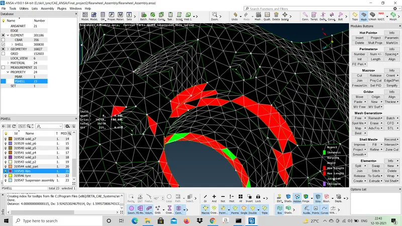
FIG 6 - Elements failing due to narrow feature
It should be noted that for fillet areas, defeaturing can be done in order to satisfy quality criteria as shown in fig 7.
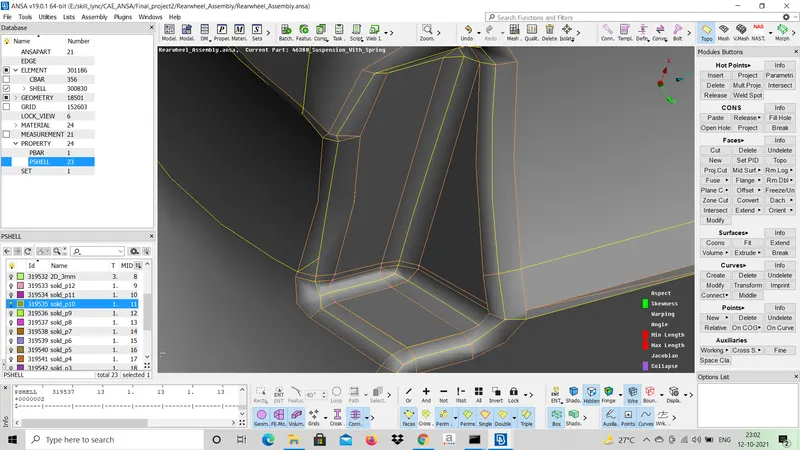
FIG 7 - Defeaturing in fillet area
Next after constructing the surface mesh, volume has to be assigned to the elements in order to convert them into 3D elements. In surface mesh, tria elements are used to capture so tetra elements are formed in solid mesh. Go to VOLUME MESH Module. So in order to perform 3D mesh first define the entire volume as closed volume by VOLUMES > DEFINE > MANUAL and select the entities to assign closed volume. As this closed volume has no definite thickness in PID MODULE no need of assigning the thickness. Next mesh the elements by UNSTRUCTURED MESH > TETRA FEM. The status of meshing can be checked in volumes list as shown in fig 8.
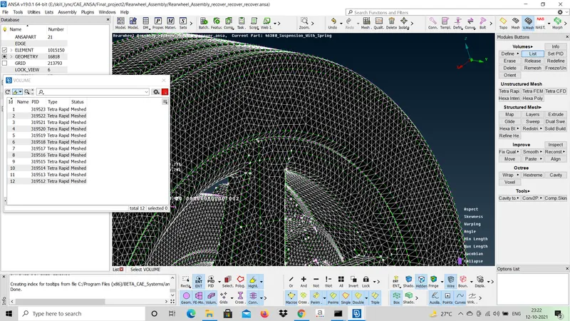
FIG 8 - Volume list
The computational time for solid mesh is higher when compared to shell mesh as in the fig 9 it is clearly shown that the elements in the 3D mesh is 2 times more compared to shell mesh elements.
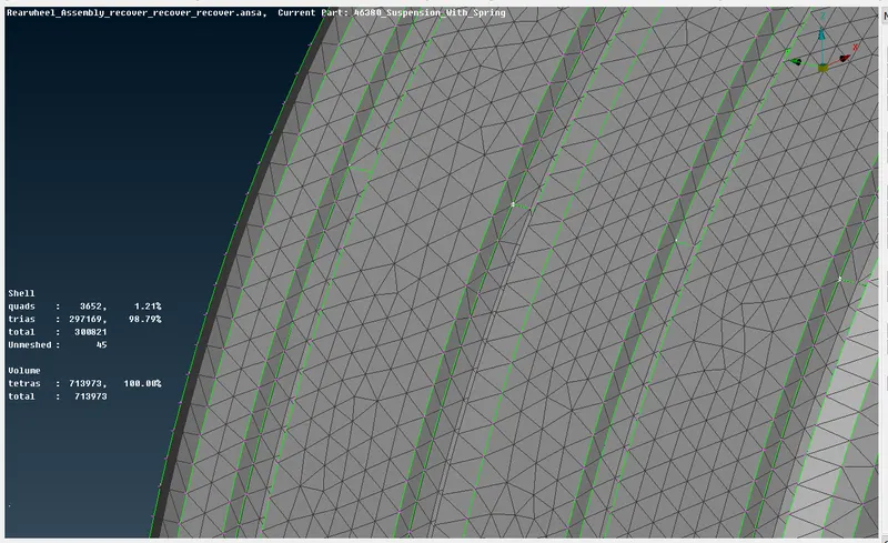
FIG 9 - Total no.of elements in shell and solid mesh
Table 4 indicates the quality parameters that to be considered in solid mesh. The elements failing the Tet-collapse are rectified by VOLUME MESH MODULE > IMPROVE > FIX QUALITY.
After performing meshing for the cad model, the next step is to make all the available connections. In order to make the connections, the mesh elements have to be released, so that the elements have no assositivity with the geometry. Depends on the type of application, the suitable deck to be selected and connections to be made. For durability analysis Abacus solver deck is to be selected, for NVH analysis Nastran solver deck is to be selected, for safety analysis LS Dyna solver deck is to be selected. The given cad model is rear suspension model and NVH analysis has to be done to the model, so connections to be made based on the Nastran solver deck.
The Bolt connection has to be made with ELEMENTS > RBE2 > MANY NODES and create two spider web which forms two master nodes and connect these two master nodes by ELEMENTS > RBE2 > TWO NODES as shown in fig 10.
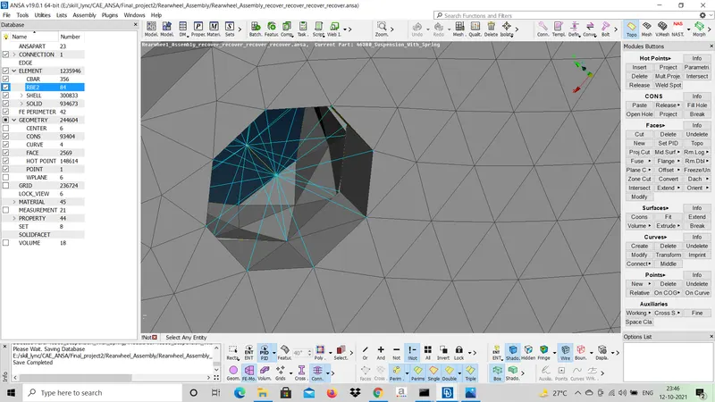
FIG 10 - Nut and bolt connection
Next for the connection as shown in the fig 11, due to the presence of suspension the connection allows transational moment in z directionthe so the DOF should not be constrained along z - direction. This was done done by ELEMENTS > INFO and select the stem of the joint and input 12456 in CM.
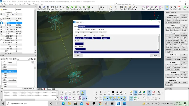
FIG 11 - Bolt connection allowing z translational motion
The cylindrical surfaces are connected by using seam weld connection. Fig 12 shows the weld connection for the cylindrical surface, as the parts are parallel to each other overlap shell connection was made.
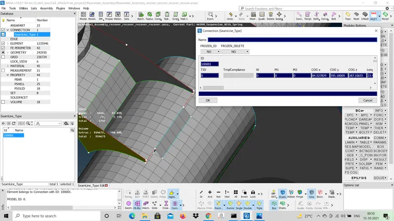
FIG 12 - Seam weld connection
For the elements as shown in the fig 13, two node RBE2 connection was done which are represented in yellow lines.
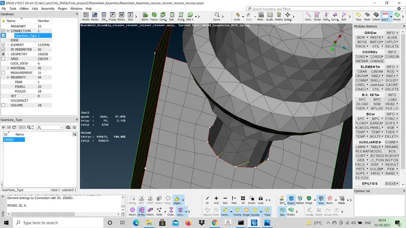
FIG 13 - Two node RBE2 connection
Spring elements are represented as CBAR type elements as shown in fig 14. This was done by creating a curve along the perimeter of the spring converting the curve to CBAR by ELEMENTS > CBAR.
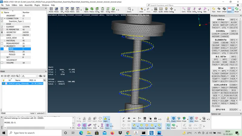
FIG 14 - Spring representation
Next after creating all the necessary connections, symmetry transform was performed by using TRANSFORM > COPY so that mirror image of the entity created as shown in the fig 15.
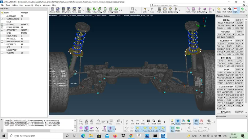
FIG 15 - Final model
LEARNING OUTCOMES:
- Fixing Topological errors
- Perform shell mehing
- perform solid meshing
- Perform symmetry operation
- CBAR representation of spring
- Assigning proper connections such as Bolt, seam weld connections
CONCLUSION:
As per the requirements all the necessary connections and good mesh flow was made on the given cad model. After Pre processing the cad model, solving and Post processing has to be done