Week-7 Head Impact
AIM:
The objective of the report is to perform HEAD IMPACT SIMULATION and calculate HIC value for various models and validate the results.
PROCEDURE:
Pedestrian protection CAE is one of the field of vehicle safety engineering from crash perspective. In pedestrian protection, conditions are examined such that imparting minimum injury to head, upper leg (thigh), and lower leg (including knee) in case of an accident with a human subject as shown in fig 1.
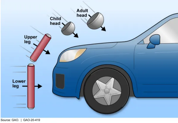
FIG 1 - HEAD IMPACT SIMULATION
From the experiments, these tests are usually done at a lower velocity from 20-40 kmph beacuse in general at time of collision, brakes are applied to the vehicle which leads to decrease in velocity.
In order to quantify the head injury, a term called HEAD INJURY CRITERION(HIC) is defined.

HIC is the maximum value over the critical time period t1 to t2 for the above expression.
CONDITIONS FOR MAXIMUM HEAD INJURY -
1) Peak acceleration value lasts 3ms, then severe head injury happens.
2) Longer deceleration times do not increase the injury risk.
So, for calculating HIC, t2 - t1 < 36ms (or) t2 - t1 < 15ms is considered.
At a HIC of 1000, there is an 18% probability of a severe head injury, a 55% probability of a serious injury and a 90% probability of a moderate head injury to the average adult.
AIS - Abbreviated injury scale is used to describe the severity of the injuries based on HIC values as shown in fig 2.
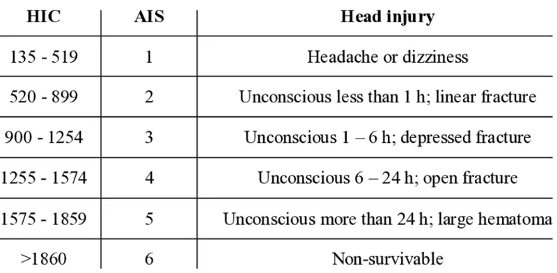
FIG 2 - AIS SCALE
PROBLEM STATEMENT -
In this report, three cases are considered to perform virtual simulations. Initially, a simple model is considered and in next cases complexity is added.
You are supposed to replicate a scenario where this headform will impact on a car bonnet. The bonnet should be considered as a rigidwall for the 1st case and while using the meshed hood model a elasto-plastic material card has to be used. From the simulation, the head impact coefficient must be calculated manually and with the help of LS-PrePost.
CASE 1 -
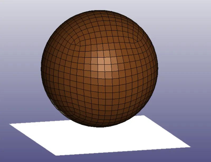
HEAD - HOLLOW SPHERE
CAR BONNET - RIGID WALL
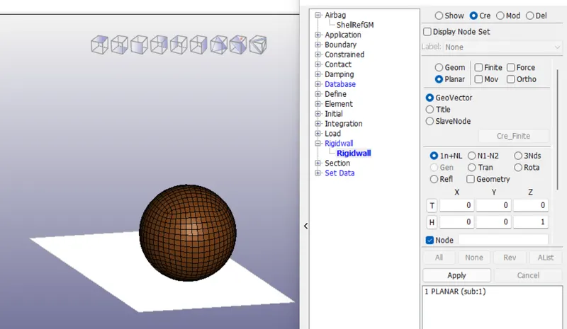
In this case, the head form is replicated by a hollow sphere and car bonnet is replicated by a rigid wall as shown in fig.
The unit system considered is kg-mm-ms.
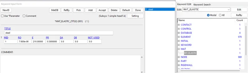
MATERIAL -
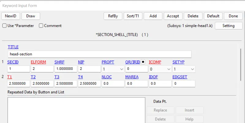
SECTION -
The shell thickness of 2.5mm is considered for head replicate.
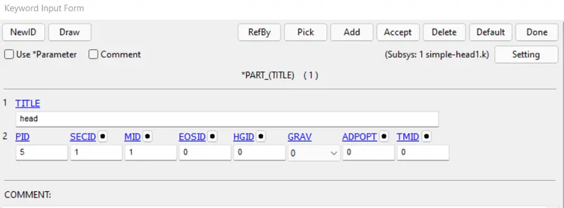
PART -
RIGID WALL -
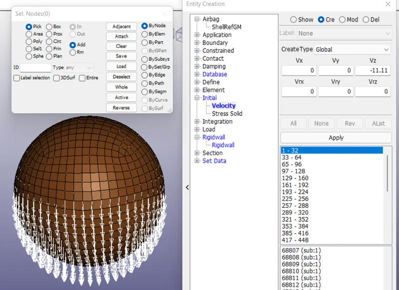
INITIAL -
Head replicate has given an initial velocity of 11.11 mm/ms.
DATABASE - KEYWORDS -
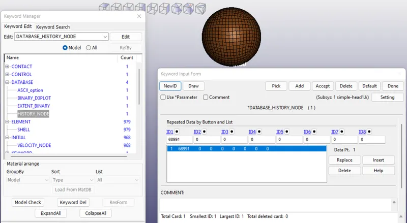
1)HISTORY NODE - In order to compute HIC values, the acceleration analysis of head is to be done at time of impact. So, consider a node at the bottom of the sphere and acceleration analysis has to be done to the node.
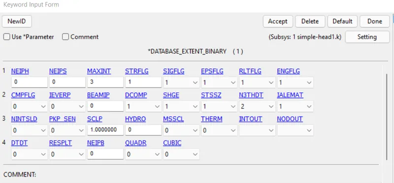
2) EXTENT BINARY - In order to visualize strain contour, set STRFLG to 1.
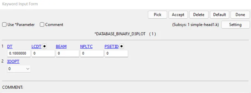
3)BINARY-D3 PLOT - Set dt to 0.01
4)ASCII_OPTION -
In ASCII_PLOTS, enable GLSTAT, NODOUT.
OUTPUT PLOTS -
The termination time is set for 5ms and results of case 1 are validated.
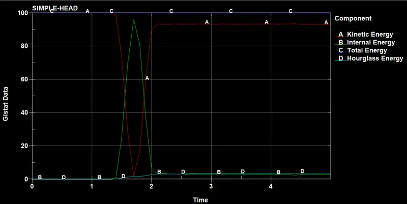
From the above fig, it is observed that in b/w 1 to 2 ms, the collision occurs. At the time of collision, the kinetic energy decreases and internal energy increases. The total energy is constant through out the simulation, which obeys law of conservation of energy. The hour glass energy is negligible compared to total energy.
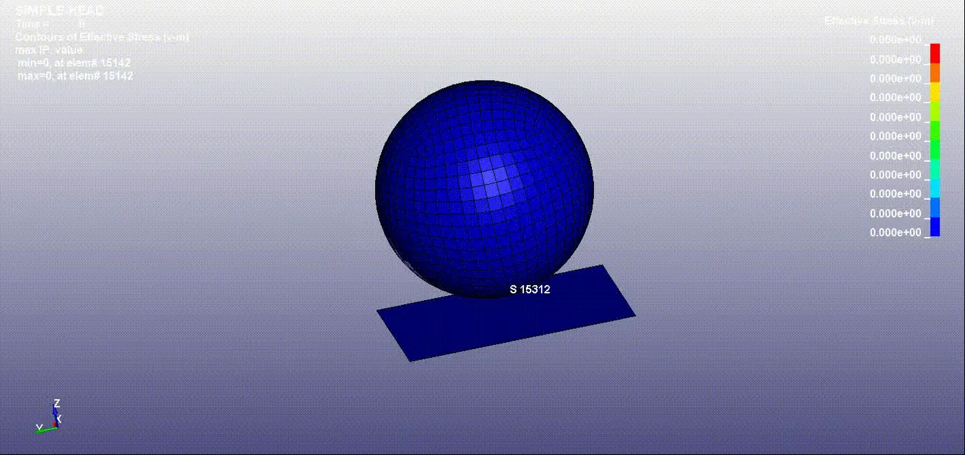
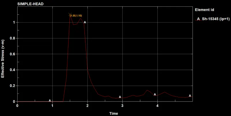
The maximum effective stress developed in the element ID 15345 is 1.50(v-m) at t = 1.10ms
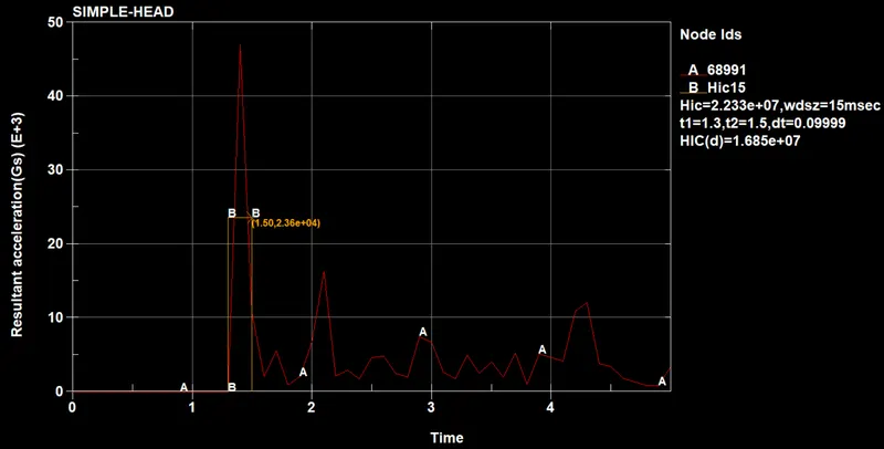
The HIC value obtained is 1.685e7, which indicates AIS level - 6, chances of severe head injury is high.
CALCULATION -
t1 = 1.3ms
t2 = 1.5ms
avg acceleration = 2.36e4
HIC = (1.5-1.3)*(2.36e4)^2.5/1000 = 1.711e7
Since, average acceleration taken is as approximate value, there is a slight difference b/w hand calculated HIC values and software calculated HIC value.
CASE 2 -
HEAD - CHILDERNS HEAD FORM MODEL
CAR BONNET - RIGID WALL
In this case, car bonnet is replicated by a rigid wall and the head is replicated by children's head form model as shown in the fig.
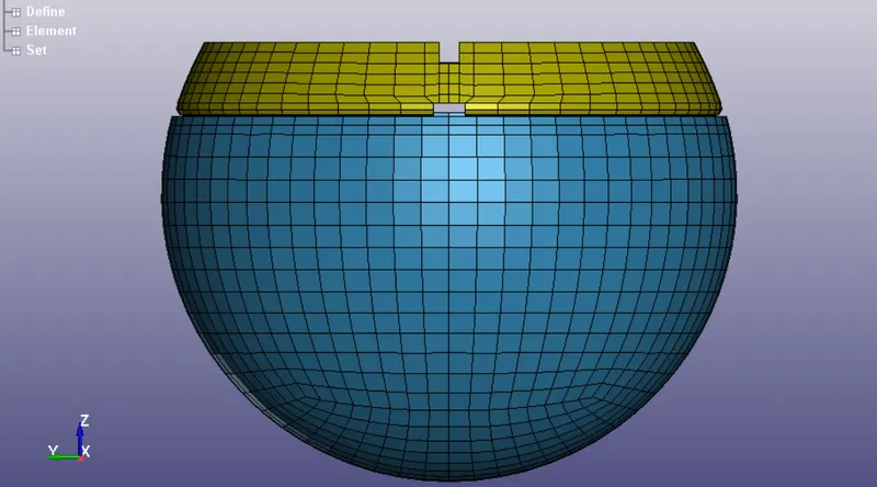
The unit system considered is kg-mm-ms.
INCLUDE -
In the above fig, the pedestrian head is aligned in the z-direction. In real life scenarios, at the time of impact, the head impacts the hood at a different impact angle which varies from 35 to 75 degrees. So, we can include multiples files in the main file with some modifications without changing the original file by using INCLUDE keyword.
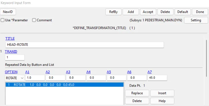
To change the impact angle in the main file, go to DEFINE > TRANSFORMATION as shown in the fig. Impact angel is 45 degrees.
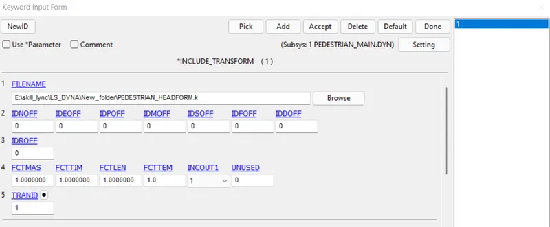
To include the file in the main file, go to INCLUDE > TRANSFORM, this keyword is used to include transformation.
MATERIAL -
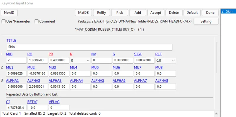
The hyper elastic material is used to define the outer skin.
PART -
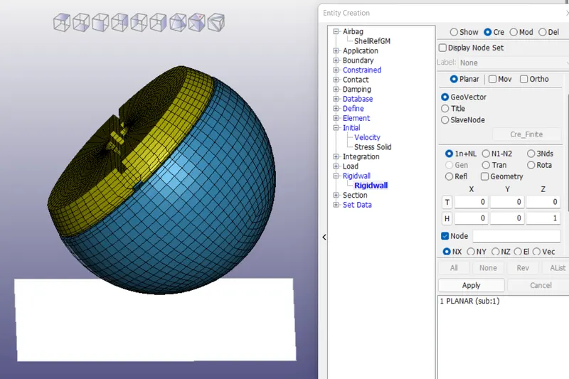
RIGID WALL -
INITIAL -
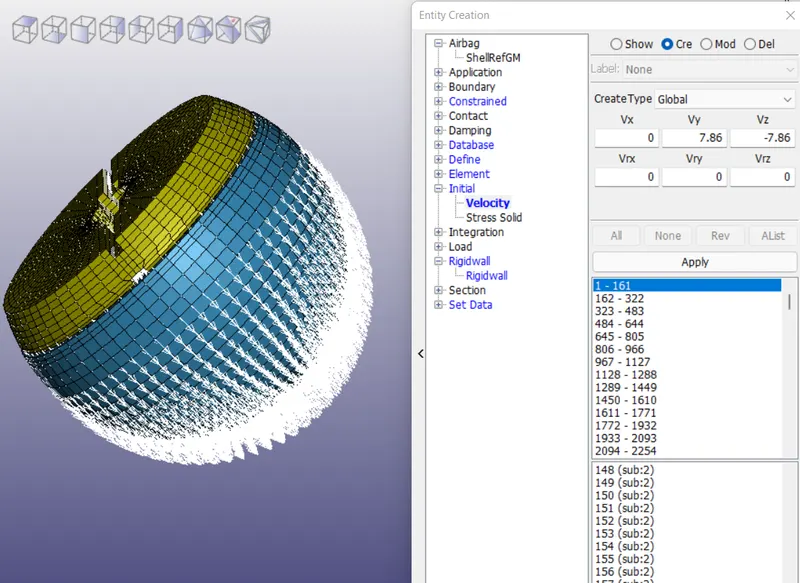
Head replicate has given an initial velocity of 11.11 mm/ms. Since, the impact angel is 45 degrees, Vy = 11.11 cos(45) and Vz = -11.11 sin(45) is given as shown in the fig.
ELEMENT KEYWORD -
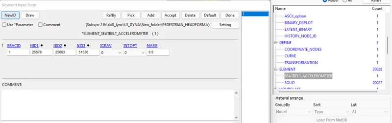
Seat belt accelerometer keyword is defined to plot the accurate value of the acceleration of a particular node.
DATABASE - KEYWORDS -
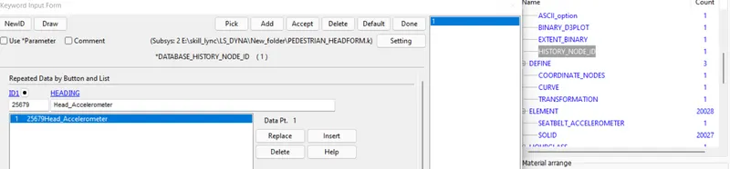
1)HISTORY NODE -
2) EXTENT BINARY - In order to visualize strain contour, set STRFLG to 1.
3)BINARY-D3 PLOT - Set dt to 0.01
4)ASCII_OPTION -
In ASCII_PLOTS, enable GLSTAT, NODOUT.
OUTPUT PLOTS -
The termination time is set for 5ms and results of case 2 are validated.
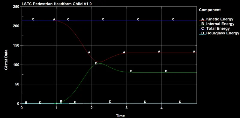
From the above fig, it is observed that the collision occurs after 1ms. At the time of collision, the kinetic energy decreases and internal energy increases. The total energy is constant through out the simulation, which obeys law of conservation of energy. The hour glass energy is negligible compared to total energy.
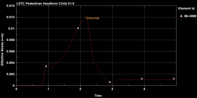
The maximum stress developed is 0.012(v-m)
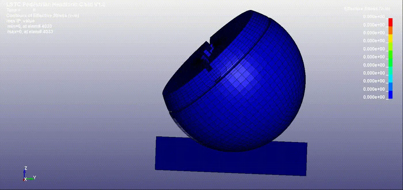
For the element ID - 3889, the maximum von-mises stress developed is 0.012(v-m) at t = 2.2 ms
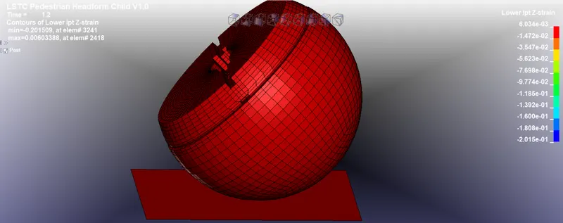
The maximum strain developed in z-direction is 0.00603 for element-2418 at t=1.2ms
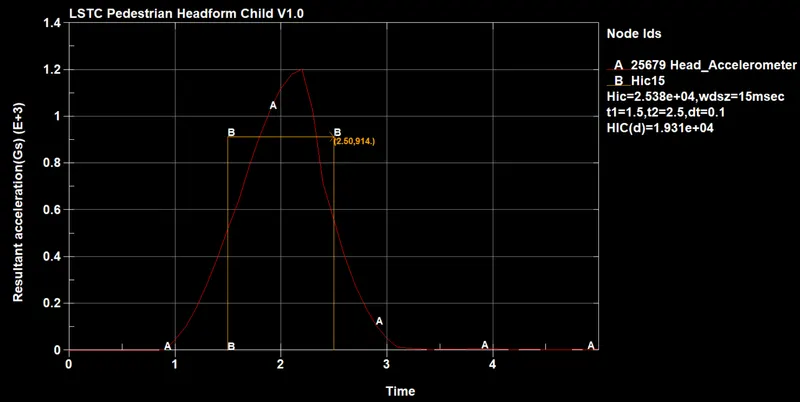
CALCULATION -
t1 = 1.5
t2 = 2.5
avg acceleration = 914
HIC = (2.5-1.5)*(914^2.5)/1000 = 2.5256e4
CASE 3 -
HEAD - CHILDERNS HEAD FORM MODEL
CAR BONNET - MESH HOOD MODEL
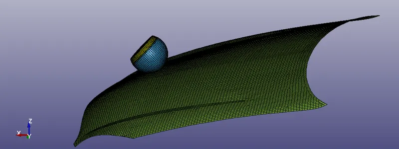
In this case, car bonnet is replicated by a mesh hood model and the head is replicated by children's head form model. The unit system considered is kg-mm-ms.
INCLUDE -
To change the impact angle in the main file, go to DEFINE > TRANSFORMATION as shown in the fig. Impact angel is 45 degrees.
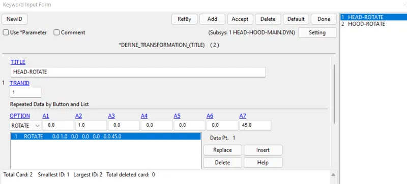
To include the file in the main file, go to INCLUDE > TRANSFORM, this keyword is used to include transformation.
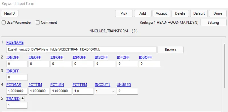
The following fig shows the main file after including the sub system files.
INITIAL -
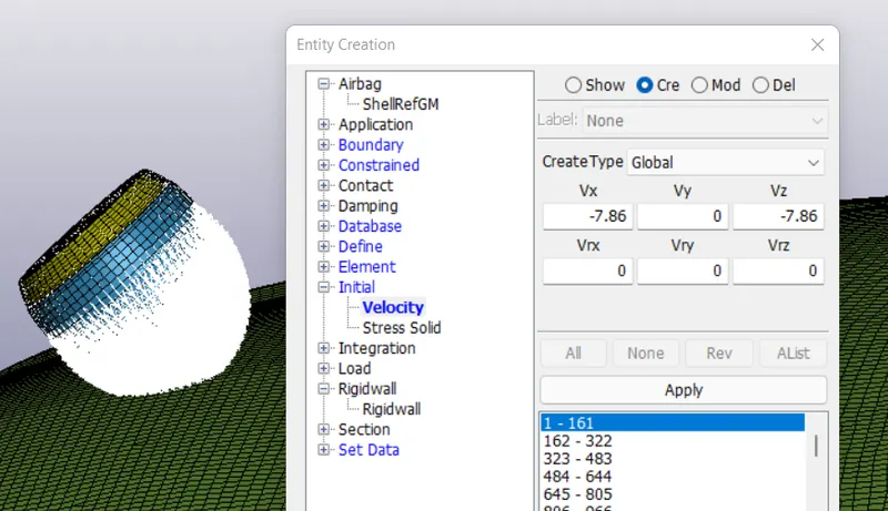
Head replicate has given an initial velocity of 11.11 mm/ms. Since, the impact angel is 45 degrees, Vx = -11.11 cos(45) and Vz = -11.11 sin(45) is given as shown in the fig.
OUTPUT PLOTS -
a) ALUMINIUM FRAME
The termination time is set for 10ms and results of case 3 are validated.
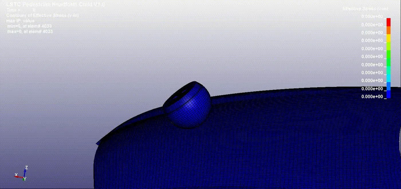
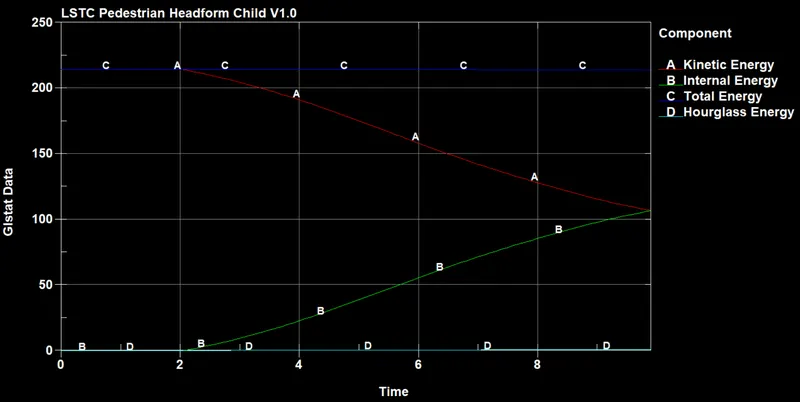
From the above fig, it is observed that the collision occurs after 2ms. At the time of collision, the kinetic energy decreases and internal energy increases. The total energy is constant through out the simulation, which obeys law of conservation of energy. The hour glass energy is negligible compared to total energy.
The maximum effective stress developed for the element - 2953 is 0.00374(v-m)
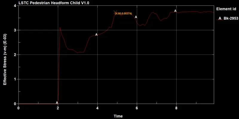
The maximum effective stress in case of hood simulation is 0.00374 , where as in rigid wall is 0.012. So, it is concluded that since rigid wall is more stiffer compared to aluminium hood, the stress generated is more in rigid wall case.
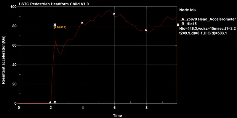
CALCULATION -
t1 = 2.2ms
t2 = 9.9ms
avg acceleration = 80.2
HIC = (9.9 - 2.2)*(80.2)^2.5/1000 = 443.533
b) STEEL FRAME
In this case, Steel material is used as the hood material of the car and the results are plotted.
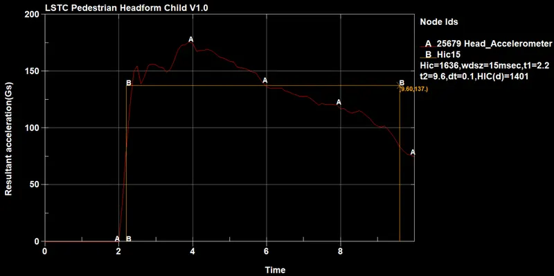
CALCULATION -
t1 = 2.2ms
t2 = 9.6ms
avg acceleration = 137
HIC = (9.6 - 2.2)*(137)^2.5/1000 = 1625.67
It is observed that since Aluminium is less stiffer than the steel, the HIC value obtained in aluminium hood is 503.1 and in steel hood is 1401 which indicates that probability of severe head injury in aluminium hood case is low.
CONCLUSION:
It is concluded that as head foam collides with stiffer object, the HIC value and stress generated is more compared to less stiffer object. So,in order to occur lower propobility of head injury, the hood material should be less stiffer.