Week - 5 - Modelling Spotwelds
AIM:
The objective is to perform simulation for Beam Spotweld and Solid Spotweld and validate the results.
EXPLANATION:
SpotWeld is one of the types of electric resistance welding. Spot welding is used to join metal sheets. In spotwelding, two copper electrodes are used to pass the electric current through the sheets that need to be welded and due to the thermal resistance offered by the sheet metals, heat is generated which leads to melting of the sheets and copper electrodes, apply the pressure on the metal sheets which leads to formation of the weld as shown in fig 1. It is recommended that distance between two spot welds should be a minimum of 10 times the material thickness.
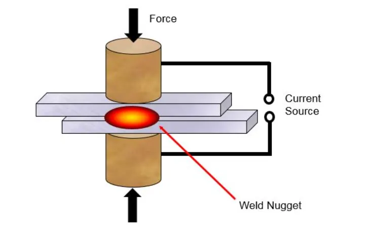
FIG 1- SPOT WELD
PROCEDURE:
In this report, the virtual simulation of Spotweld is performed in LS-DYNA. So first import the file in LS-PRE POST as shown in fig2. LS-DYNA by default do not follow any unit system and has to be defined by the user. So, in this model g-mm-ms unit system is followed.
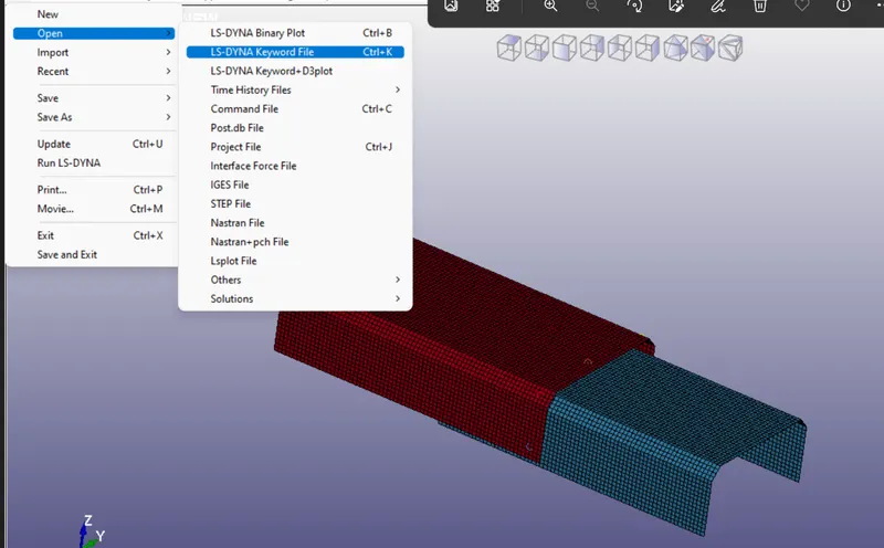
FIG 2- SPOTWELD MODEL
In this report, Beam and Solid spot welds are created.
1. Beam Spot Weld -
Beam Spotweld is a 2D representation of Spotweld and is created by beam-type element. To create Beam spotweld, go to ELEMENT AND MESH > ELEMENT GENERATION > BEAM > BEAM BY_TWO NODE SETS and select two node sets of spotweld element as shown in fig 2.
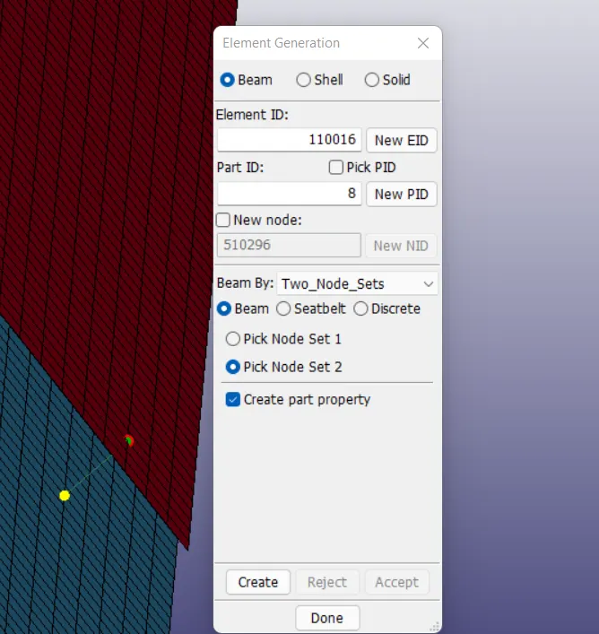
FIG 3- BEAM SPOTWELD
Material -
MAT_001_ELASTIC keyword is assigned to the two plates as per the material properties as shown in Table1.
| Material | Density | Youngs modulus | Poisson ratio |
| Steel | 7800 kg/m3 | 210GPa | 0.3 |
TABLE 1 - MATERIAL PROPERTIES OF PLATES
MAT_100_SPOTWELD keyword is assigned to the beam spotweld as per the material properties as shown in Table2.
| Material | Density | Youngs modulus | Poisson ratio | Yield stress |
| Steel | 7800kg/m3 | 210GPa | 0.3 | 1000Pa |
TABLE 2 - MATERIAL PROPERTIES OF SPOTWELD
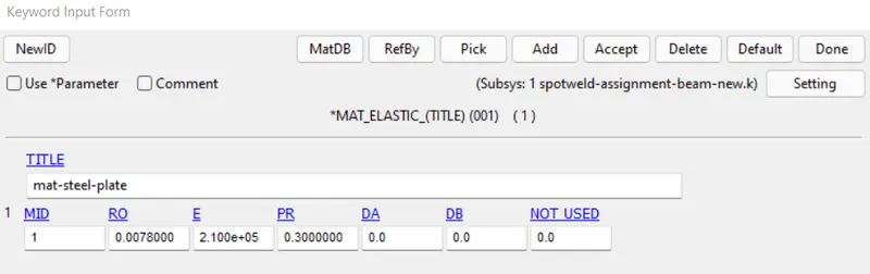
FIG 4- MATERIAL CARD OF PLATE
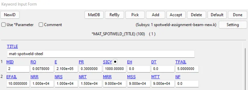
FIG 5- MATERIAL CARD OF SPOT WELD
SECTION -
The Section keyword is assigned to these parts by MODEL AND PART > KEYWRD > SECTION.
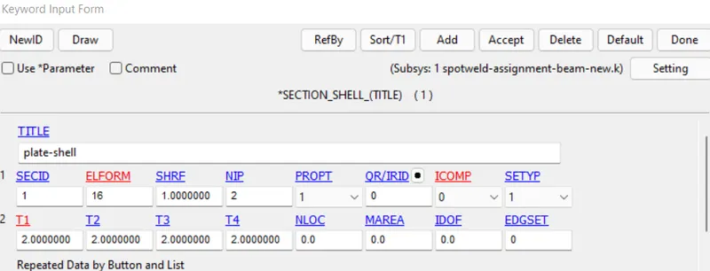
FIG 6- SHELL_SECTION CARD OF PLATE
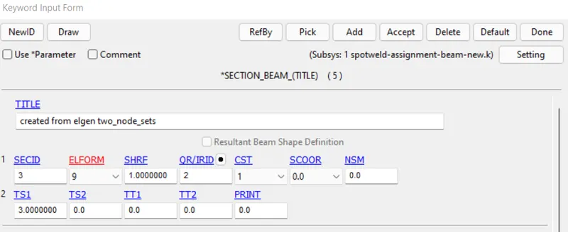
FIG 7- BEAM_SECTION CARD OF WELD
CONTACT -
For Beam-spotweld, Contact keyword as shown in fig -8 is allotted.
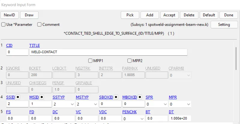
FIG 8- CONTACT_KEYWORD FOR SPOTWELD AND PALTE
BOUNDARY CONDITIONS -
One end of the Bottom plate is constrained in all directions and another end of Top plate is given prescribed motion as shown in fig 9.
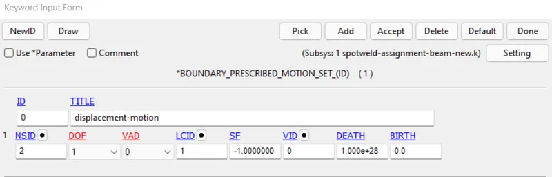
FIG 9- PRESCRIBED_MOTION-KEYWORD
TERMINATION-
Set the termination time as 10ms.
2. Solid Spot Weld -
Solid Spotweld is a 3D representation of Spotweld and is created by solid-type element. To create solid spotweld, go to ELEMENT AND MESH > ELEMENT GENERATION > SOLID > SOLID BY_SHELL DRAG and select the shell element to which spot weld has to be attached and assign the thickness and segment values as shown in fig 10.
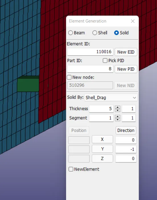
FIG 10 - SOLID_SPOTWELD
If two shell elements are not parallel, then there will be no node associtivity for the solid-spotweld. So inorder to have node associtivity, paste the node elements of the solid spot weld to the shell element of the plate by ELEMENT AND MESH > NODE EDITING > REPLACE and select the node pairs to be pasted.
SECTION -
The Section keyword is assigned to these parts by MODEL AND PART > KEYWRD > SECTION.
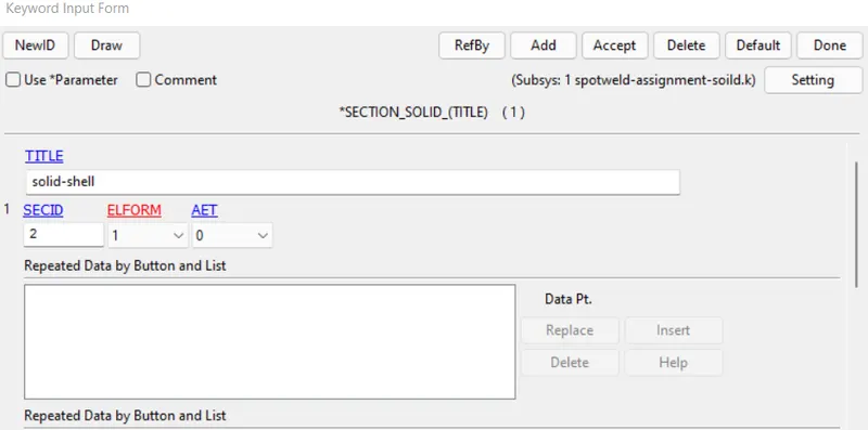
FIG 11 - SOLID_SECTION CARD OF SOLID SPOTWELD
CONTACT -
For Solid-spotweld, Contact keyword as shown in fig -12 is allotted.
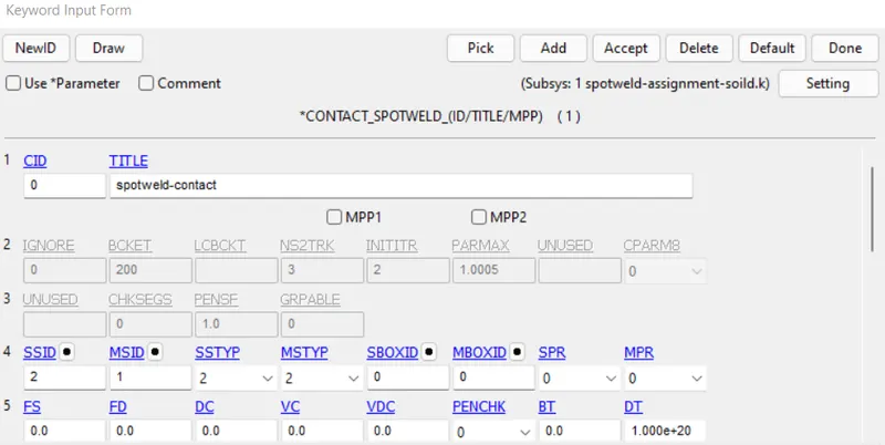
FIG 12- CONTACT_KEYWORD FOR SOLID SPOTWELD AND PLATE
The mentioned above cards differ to model Solid spot weld from Shell spot weld and the remaining steps are same for both.
TERMINATION -
In control keyword, global settings for the entire analysis can be done. Control_Termination keyword is used to assign the time for the simulation. In this model end time of 10ms is given. In fig-13, it is shown that the beam element failed at 5.0004ms.
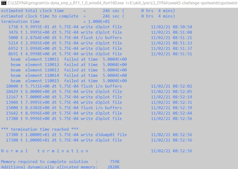
FIG 13- LAUNCH MANAGER
RESULTS:
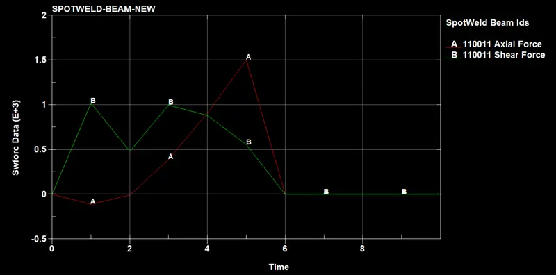
FIG 14 - AXIAL AND SHEAR FORCE DEVELOPED IN BEAM SPOTWELD
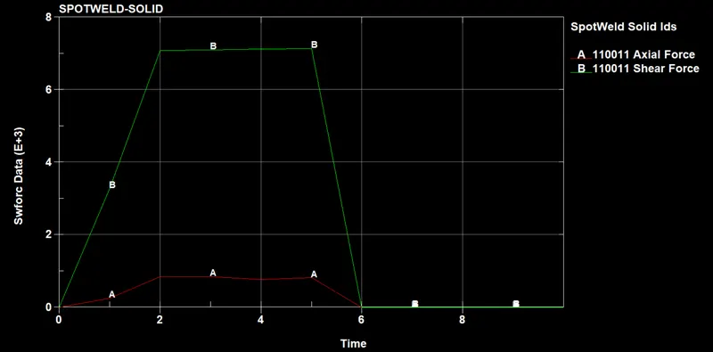
FIG 15 - AXIAL AND SHEAR FORCE DEVELOPED IN SOLID SPOTWELD
Fig 16,17 shows the resultant forces developed in the Spotwelds. It is observed that solid spot weld offers more resistance to deformation compared to Beam spotweld as resultant force developed in the Solid spotweld is more.
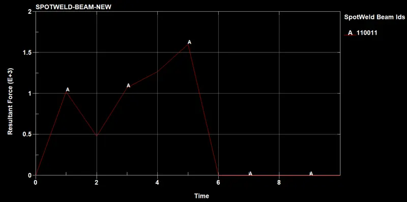
FIG 16- RESULTANT FORCES DEVELOPED IN BEAM SPOTWELD
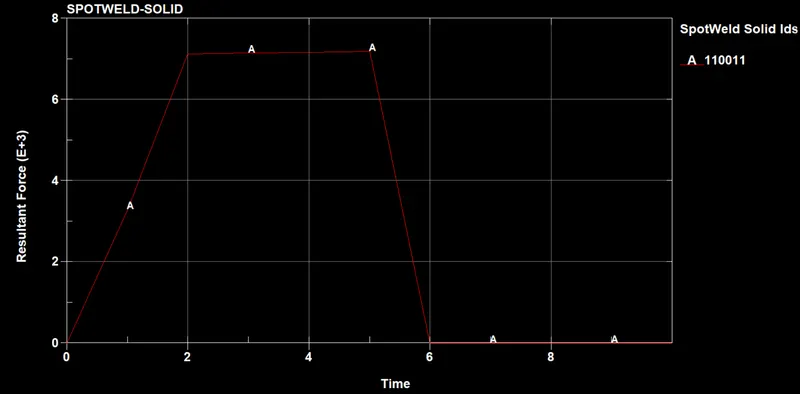
FIG 17- RESULTANT FORCES DEVELOPED IN SOLID SPOTWELD
Fig 18 and Fig 19 shows X component stress developed in the plates at time 4.9998 ms just before the failure of the spotwelds. It is observed that stress developed in solid spotweld parts is more compared to stress developed in Beam soptweld parts, which indicates the solid spot weld shows more rigidity compared to Beam spotweld.
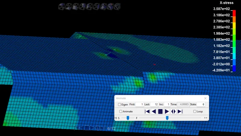
FIG 18- X-STRESS DEVELOPED IN BEAM SPOT WELD PLATES
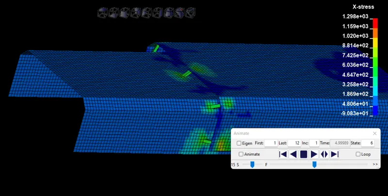
FIG 19- X-STRESS DEVELOPED IN SOLID SPOT WELD PLATES
Fig 20,21 shows the Energy plots and it is observed that the Hourglass energy is neglected compared to total energy. It is observed that since Solid spot weld offers more rigidity, the Internal energy for Solid spotweld is more compared to Beam spotweld and the kinetic energy for Beam spotweld plate is 5.04e4 at 10ms and for Solid spotweld plate is 4.95e4 at 10ms.
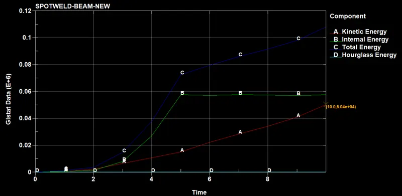
FIG 20 - ENERGY V/S TIME FOR BEAM SPOTWELD
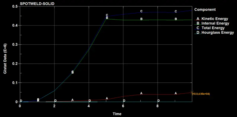
FIG 21 - ENERGY V/S TIME FOR SOLID SPOTWELD
CONCLUSION :
The Spotweld simulation was performed and the results are validated. By analysing the results, the Solid spot weld offers more resistance compared to Beam spotweld.