Week - 3 Drop test Challenge
AIM:
The objective is to perform a drop test for the cell phone model and validate the results.
PROCEDURE:
Generally, Drop test method is performed on the components to check the structural integrity of a product. By performing these tests, the weaker areas of a product can be visualized and the design engineer has a scope to redesign the product. LS-DYNA by default do not follow any unit system and has to be defined by the user. So, in this model kg-mm-s unit system is follwed.
In this model, drop test of a cell phone has to be performed by inputting required parameters. First import the file in the LS-PREPOST tool as shown in the fig 1.
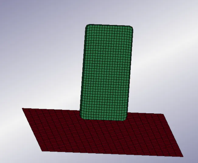
FIG 1- CELL PHONE MODEL
The model consists of two parts as shown in the fig1, the green part represents the cell phone case and red part indicates the floor or base on which cell phone is dropped. The material properties has to be assigned to these parts by MODEL AND PART > KEYWRD > MAT.
MATERIAL -
- MAT_24_PIECE WISE LINEAR PLASTICITY keyword is assigned to phone as per the material properties as shown in Table1.
| Material | Density | Youngs modulus | Poisson ratio | Yield stress | Ultimate strength | Tangent Modulus |
| aluminium alloy | 2710 kg/m3 | 70 GPa | 0.3 | 276MPa | 310 MPa | 562 MPa |
TABLE 1 - MATERIAL PROPERTIES OF PHONE CASE
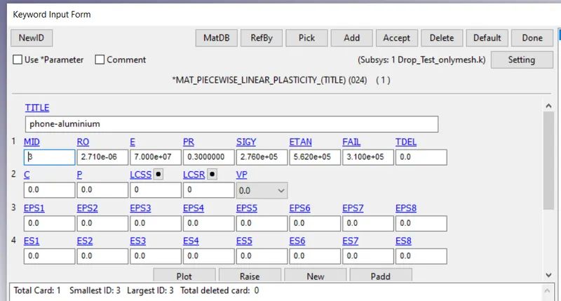
FIG 2 - MATERIAL CARD OF CELL PHONE CASE
- MAT_20_RIGID keyword is assigned to the base and it is constrained in all directions.
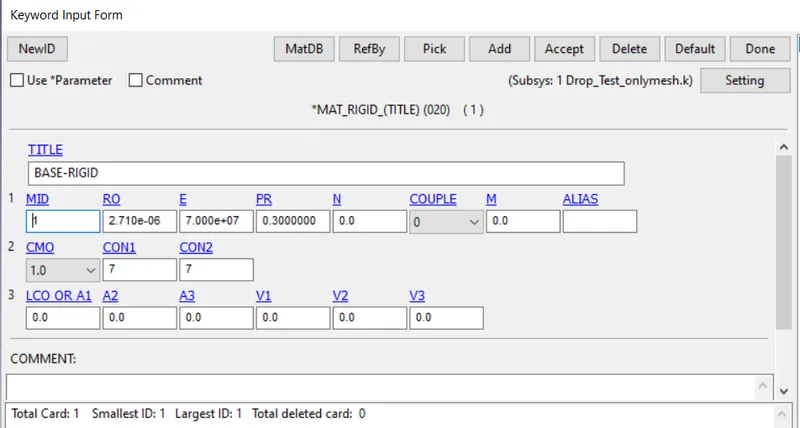
FIG 3 - MATERIAL CARD OF FLOOR
SECTION -
The Section keyword is assigned to these parts by MODEL AND PART > KEYWRD > SECTION.
The fig 4 shows the section card of phone case. Since the phone mesh is solid, solid section card is assigned to the phone case.
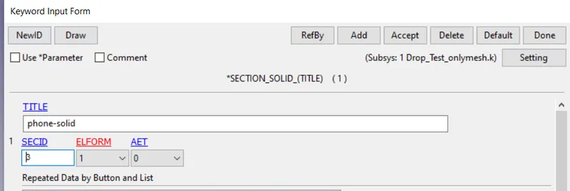
FIG 4 - SECTION CARD OF PHONE CASE
The fig 5 shows the section card of floor. Since the floor is meshed by shell elements, Shell section card is assigned to the floor with shell thickness of 10mm.
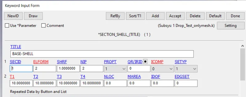
FIG 5 - SECTION CARD OF FLOOR
PART -
In part keyword assign the respective material and and section ID to the respective parts.
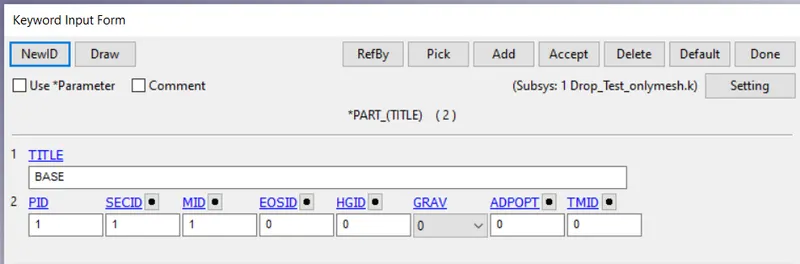
FIG 6 - PART CARD OF FLOOR
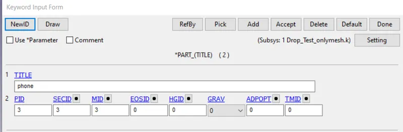
FIG 7 - PART CARD OF PHONE CASE
CONTACT -
The purpose of Contact keyword is to make sure that the two parts do not pass through each other. Based on the type of interaction different contact keywords are defined. The fig 8 shows the contact type in this model.
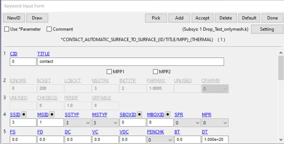
FIG 8 - CONTACT KEY WORD CARD
INITIAL CONDITIONS -
In this model, since the phone is dropped from a certain height, a certain velocity of 60 mm/s is given in the negative z-direction as an initial condition. This was done by MODEL AND PART > ENTITY CREATION > INTIAL > VELOCITY.
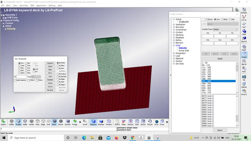
FIG 9 - INITIAL CONDITION
TERMINATION -
In control keyword, global settings for the entire analysis can be done. Control_Termination keyword is used to assign the time for the simulation. In this model end time of 0.5sec is given.
DATA BASE -
This keyword allots different types of output files which is used for post processing purpose. In this model 2 types of keywords are defined- 1)Binary_D3 plot 2)ASCII_OPTION. The Binary_D3 plot visualize the data only in the form of plots, where as in ASCII_OPTION, the ouput data can be visualized in plots and text files.
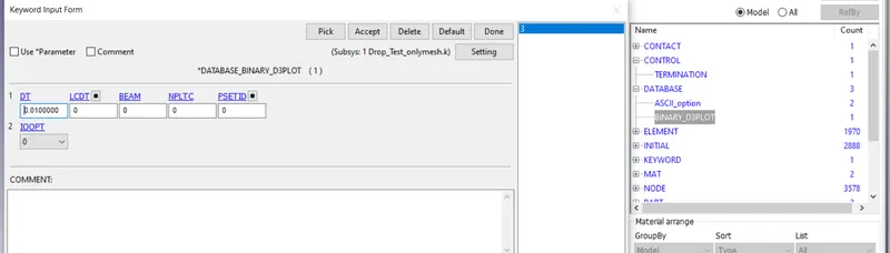
FIG 10 - Binary_D3 plot KEYWORD
MODEL CHECK -
After providing all the necessary input conditions, the final step of pre-processing unit is to check for errors and this was done by MODEL CHECK > KEYWORD CHECK. In the fig 11 as there are no errors in the model, next step is to do solving.
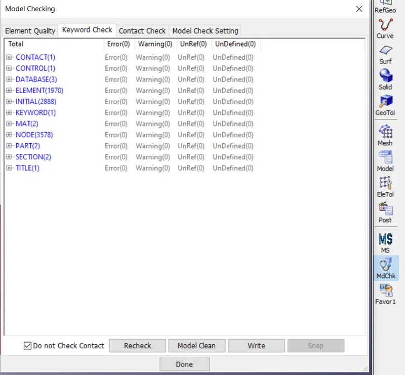
FIG 11 - MODEL CHECK
Next, run the file in LS-DYNA - LAUNCH MANAGER, fig 12 shows the computational time, number of CPU required in order to run the model and NORMAL TERMINATION indicates the simulation was done without any errors.
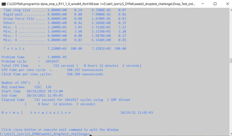
FIG 12 - LAUNCH MANAGER
RESULTS :
Next, the results can be validated by importing the d3plot file in the LS-PREPOST.
Fig 11 and fig 12 shows the von misses stress developed in the parts due to impact. Since, the base is considered as RIGID body, no stress is developed in the base plate.
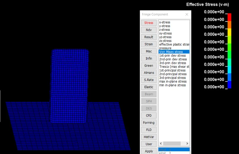
FIG 13- BEFORE IMPACT
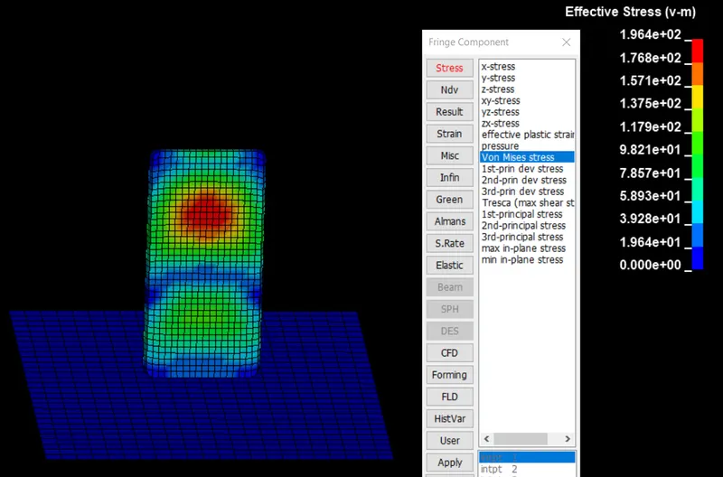
FIG 12 - AFTER IMPACT
Fig 13 shows the stress developed in z-direction due to impact. In the drop test, since the phone case is dropped in the z-direction, max stress is developed at the impact region indicated in RED colour.
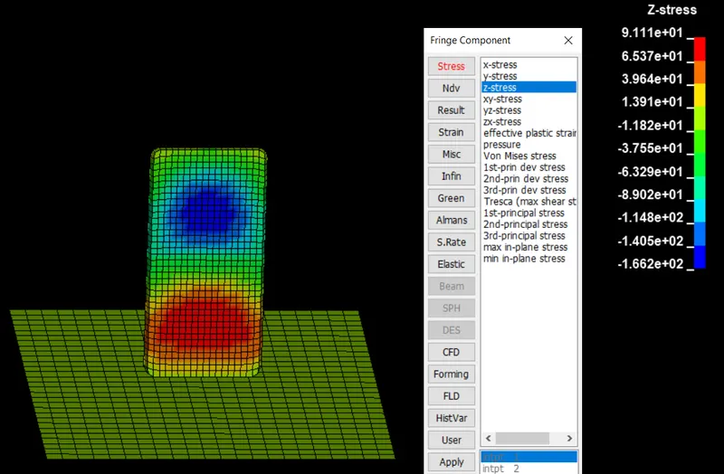
FIG 13- STRESS DEVELPOED ALONG Z -DIRECTION AFTER IMPACT
From fig 14, it is visualized that since the impact occurs between 0.2 and 0.3 sec, there is increase in Internal energy. Due to Impact, velocity of phone case is decreased which results in decrease of kinetic energy. From fundamental laws of physics, the energy is neither created nor destroyed, So the total energy should be constant in any model but tolerance up to 5% error is accepted.
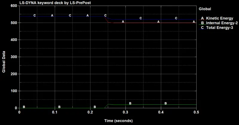
FIG 14- ENERGY V/S TIME
CONCLUSION :
The Drop test simulation was performed and the results are validated. By analysing the results, the design engineer may opt for design changes if the results are not satisfying the criteria and again simulation has to be performed with the new design. If the results satisfy the requirement for public usage then the design will be approved for Production.