ANSYS Week 1 Stress Concentration on a Plate with hole
Week 1: Stress Concentration on a plate with a hole
OBJECTIVE:
Two cases are provided with a different design, two bars to design and analysis with Total deformation and equivalent stress in the model
Case 1:
Length: 300mm
Height: 120mm
The hole at the center with diameter: 60mm
Thickness: 30mm
Case 2:
Length: 300mm
Height: 120mm
The hole at the center with diameter: 60mm
Thickness: 30mm
Boundary conditions plate fixed on the left face.
A load of 500N on the right face
PROCEDURE
Case 1: Assign the static structural material with additional material of stainless steel in the engineering data library.
Creating the geometry with the given dimension, a center hole with a plate of length 300mm, Height 120mm, Hole at the center with diameter 60mm, thickness 30mm.
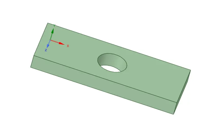
Fig 1: Plate with a single hole (Case 1)
Now getting the model open in the mechanical, checking the geometry and material are checked, given the mesh to the geometry with 5mm size, and then inserting the tetrahedrons as the method.
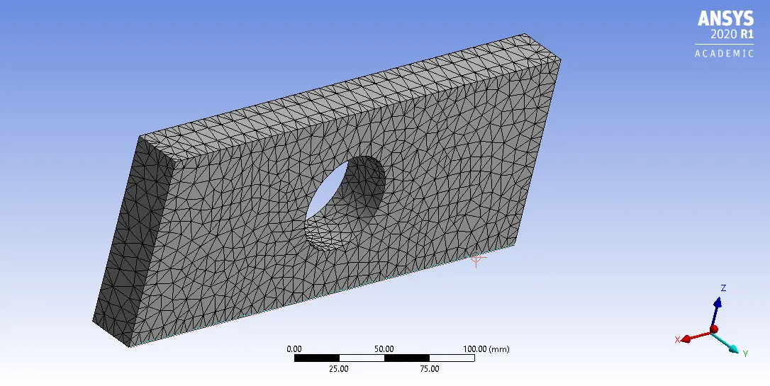
Fig 2: Tetra mesh (Case 1)
In the Static Structural, giving the left face of the body as fixed support and then at the right face giving the 500N of the force of the analysis of the model.
Command: [Static Structural (Insert + Fixed support + select face) + (Insert + Force + Define: components + Coordinate system : x direct: -550 N)]
Case 2: Assign the static structural material with additional material of stainless steel in the engineering data library.
Creating the geometry with the given dimension, a center hole with a plate of length 300mm, Height 120mm, Hole at the center with diameter 60mm and other two holes apart from the center hole which at 90mm both sides with a diameter of 30mm, thickness 30mm.
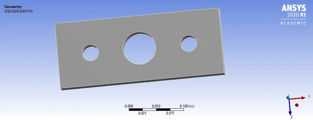
Plate with 3 holes (Case 2)
Now getting the model open in the mechanical, checking the geometry and material are checked, given the mesh to the geometry with 5mm size, and then inserting the tetrahedrons as the method.
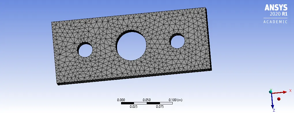
Fig 3: Mesh Case 2
In the Static Structural, giving the left face of the body as fixed support and then at the right face giving the 500N of the force of the analysis of the model.
Note:
- Units are used in mm, MPa, and cores 2
RESULT
For analysis solution solving case 1 with structural steel material and solving Case 2 with the same material, the total deformation is calculated and Equivalent stress on both plates.
Comparing both results of total deformation and equivalent stress
Total Deformation
| Case | Minimum deformation (mm) | Maximum deformation (mm) | Average deformation (mm) |
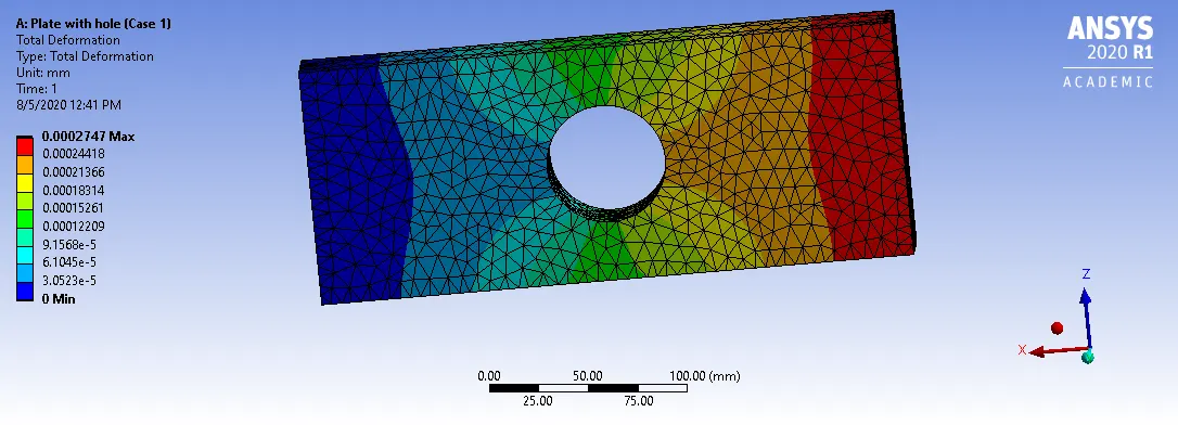
| 1 | 0 | 0.0002747 | 0.00013861 |
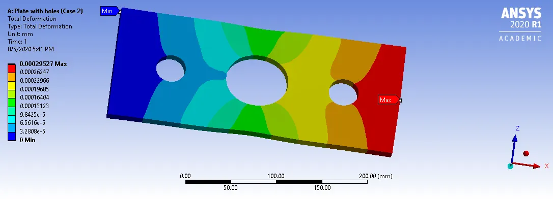
| 2 | 0 | 0.00029527 | 0.00014517 |
| Case 1 | Case 2 |
|
Fig 4: Total deformation Case 1 |
Fig 5: Total Deformation Case 2 |
Equivalent Stress
| Case | Minimum stress (MPa) | Maximum stress (MPa) | Average stress (MPa) |
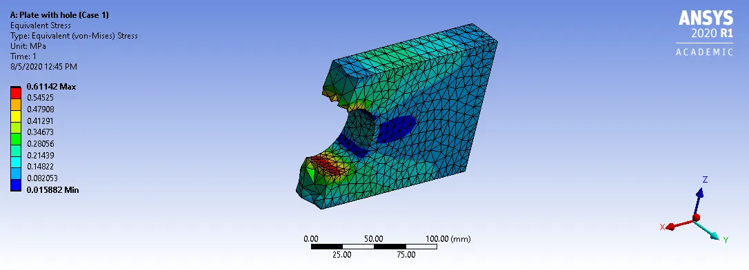
| 1 | 0.015882 | 0.61142 | 0.17008 |
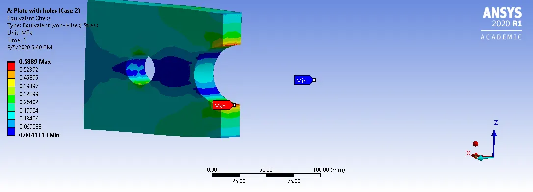
| 2 | 0.0041113 | 0.5889 | 0.16871 |
| Case 1 | Case 2 |
|
Fig 6: Equivalent stress Case 1 |
Fig 7: Equivalent stress Case 2 |
CONCLUSION
Comparing the total deformation and stress developed in both cases
The average value of the total deformation in case 1 0.00013861mm is and case 2 0.00014517mm which has a slight value difference in Case 2 due to the plate with a number of holes and the average value of stress in Case 1 is 0.17008MPa and Case 2 is 0.16871MPa as the stress concentration is at the center of the hole is higher in the plate 1 and it is less in the plate 2 because of stress distribution in the overall plate due to the number of holes in the design as compared to plate 1 with a single hole.
Analysis point of view
The maximum and average stress in Case 2 is comparatively lesser than Case 1 due to the stress distribution in an overall plate and lesser stress concentration in the center hole, also the deformation from the point of application to the given support at 1 face is very small in Case 2.
Manufacturing Point of View
The production comes under many factors such as machinery, manpower, production cost, time, etc. Case 2 should be less preferable because of the design with 3 holes which might increase more scrap work and also may lead to damage in the material while manufacturing whereas Case 1 with a single hole is efficient to get production complete with a lesser amount of production errors and scrap material