ANSA Week 6 challenge
AIM
Apply different types of 1D connection using the NASTRAN profile on the rear door FE model.
OBJECTIVE
The rear door model is given for the connections using different types of 1D connections whichever suitable and makes the proper connections and attaches the FE model to give a model for the simulation process.
SUMMARY
NASTRAN (NVH)- The NVH stands for noise, vibration, and harshness study and modification of noise and vibration characteristics of vehicles. Noise and vibration can be readily measured, harshness is a subjective quality and is measured via jury evaluation or with analytical tools.
Connections and their types- The FE model is the same form of model creation through the 1D, 2D or 3D elements and they required to be joint through-bolt, welding, adhesive, etc. connections, There are many types of connection in the NAS profile such as RBE2, RBE3, spot weld, seam weld, etc. whereas RBE2 and RBE3 ar rigid elements.
PROCEDURE
The rear door model is inputted by the NASTRAN profile, the FE model with no geometry has the same PID for the whole component, so to realize all connection at every different part the model has been created with different PIDs.
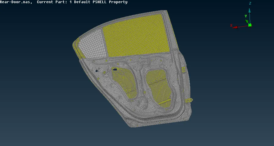
Fig 1: Rear door
Selecting the PID regions helps to visualizes every part of the rear door.
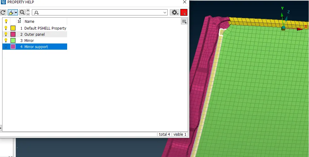
Fig 2: Assigning PID
The hinge part is an important part connected with the outer surface of the rear door connected with the outer body of the vehicle has given the rigid connection of bolt as RBE2 elements.
Forgiven RBE2 connections there are several ways with a single surface, 2 surfaces, and 3 Surface, first with 3 surfaces are connected with COG point and converting them as 3D spot weld selecting those as master and remaining nodes as slaves the different set of RBEe2 element is created.
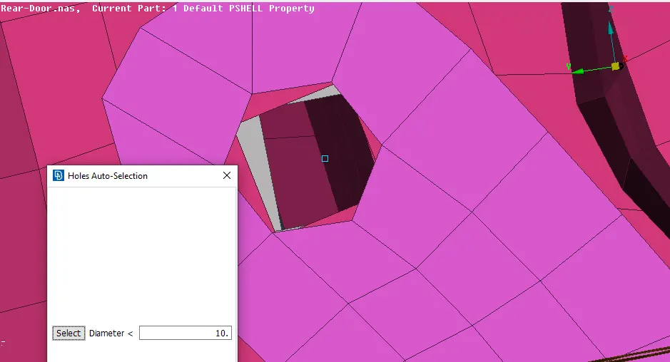
Fig 3: COG point door hinge
A different set has been created for RBE 2 elements because the body has many connections and to determine them easily they are created with groups.
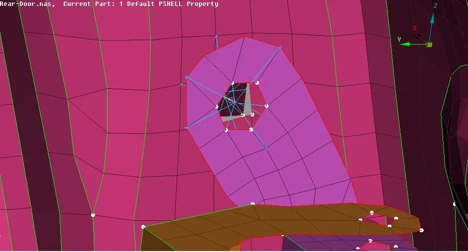
Fig 4: Hinge RBE2 connections
The single hole has given the zone cut of 3mm to obtain proper connections, they are followed with RBE2 connections and two surfaces have given the cluster RBE2 connections.
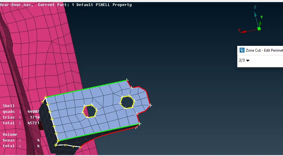
Fig 5: Zone cut
The door is moving part of the vehicle body and to move them in the simulation process he connection should also be made adequately. To have a correct connection to the hinge part which connected ith the other part of the vehicle body the connection with the Z-axis as rotational is remove with a degree of freedom (DOF).
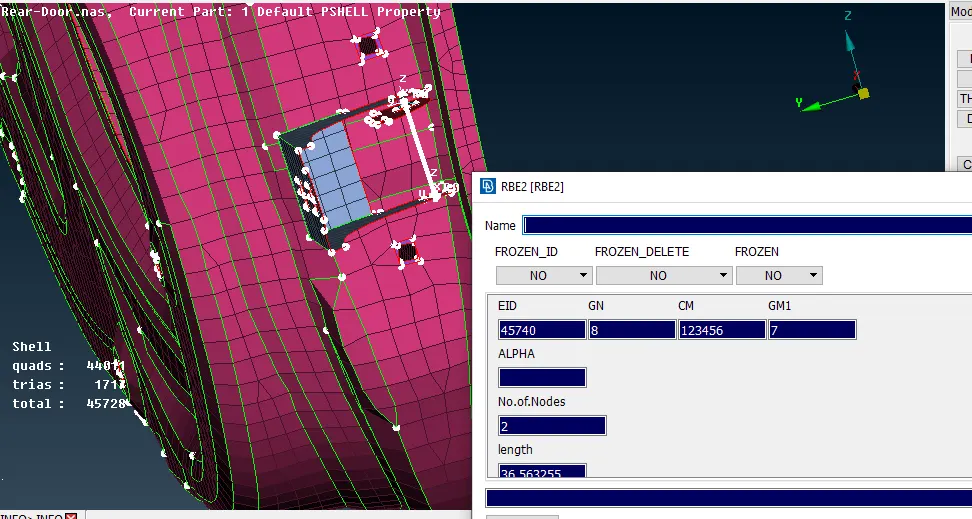
Fig 6: Removing DOG for z-axis
The other connection is deployed wherever required in the inner panel, outer panel, railing, or at the glass sie of the rear door model. Those connections are rigid connections with RBE2 elements on a single surface of the two surfaces cluster RBE2 connection.
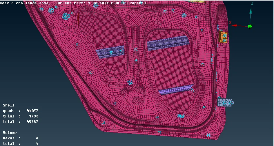
Fig 7: RBE 2 and cluster connection
Some parts at the railing are required with spot weld, to obtain those connections they are connected with RBE2 Hexa RBE2 connections with giving the Solid PID and for P1 and P2 as they initial and secondary surface. First, they are created with a 3D point converting them and giving connections of RBE3 Hexa at the connection manager.
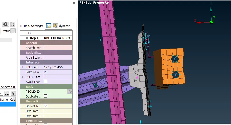
Fig 8: Connection manager spot weld
Giving the values and input in the connection manager the spot weld is deployed with on railing system
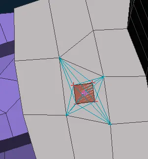
Fig 9: Spot weld
The handle is also the second important connection of the door those two holes at the handle are connected with RBE2 rigid elements and the master node of both connections is connected with a two-node connection non them to apply conmi mass. The two-node connection will give the master node in the middle so applying mass in the middle of 0.0001 tonnes for the simulation process. To apply the mas giving command at CONMi, with nodes selection an selecting the master node and giving value 100 gram as equivalent to 0.0001 tonnes.
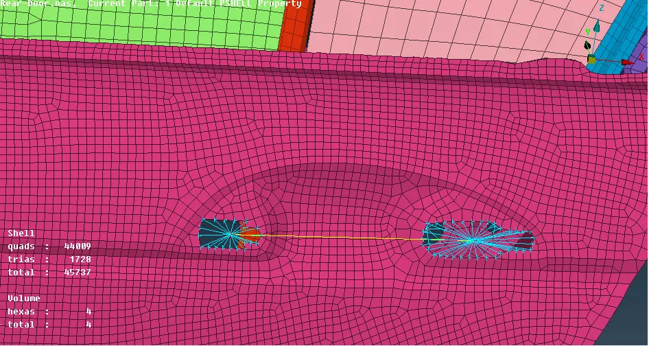
Fig 10: Handle connection

Fig 11: Applying conmi mass at the handle
The glass part is connected with the PBUSH connection. The procedure to get the PBUS first selecting the edges of the glass and creating the feast 2curve and at the base copying the curve at a distance of 10, those curves are converted to spot weld and selecting that connection is given appropriate value in the connection manager by selecting S = 10, P1 and P2 wherever required necessary P3 is due to the three surfaces. The PID for the bush is given with stiffness value.
| K1 | K2 | K3 | K4 | K5 | K6 |
| 0.001 | 0.001 | 0.001 | 10 | 10 | 10 |
And the search distance of 50 and taking all branches selected applying and realizing the bush.
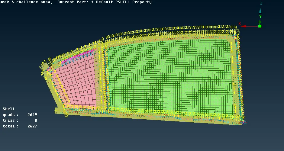
Fig 12: PBUSH Connection
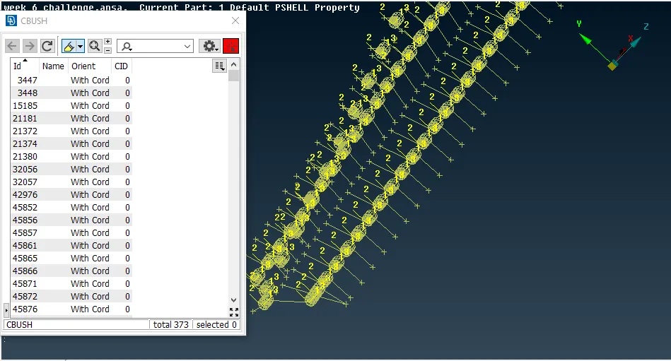
Changing the PBUSH coordinate along to the coordinate system by giving orientation and cord value as 0.
RESULTS AND CONCLUSION
The rear door has an important aspect of connection in the vehicle body they are connected with several rigid elements, spot weld, and Bush elements. To deploy the proper connection they are input with exact values and the group of RBE2 elements set is created to determine them easily and this challenge is also overcome with other elements such as spots weld, handles CONMi mass, bolt, and RBE3 Hexa (PBUSH).
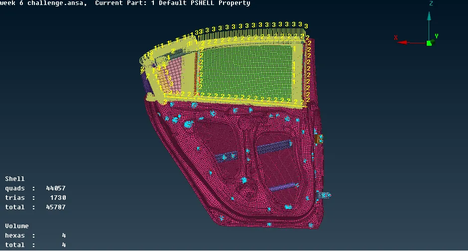
Fig 13: Rear door connection