Hypermesh Challenge _09: Create connectors and attach various parts of the given model.
Hypermesh Challenge _09: Create connectors and attach various parts of the given model.
OBJECTIVE
Creating the various connectors from 1D, 2D, or 3D as suitable connectors such as spot, bold, seam, and area respectively and attach the various parts with these connectors.
PROCEDURE:
The model frame assembly has 9 parts such as front truss 1, front truss 2, rienf_plate, right rail 1, right rail 2, left rail 1, left rail 2, rear truss 1, rear truss 2, and they have attached with different types of connectors to different parts respectively as mentioned below in the table:
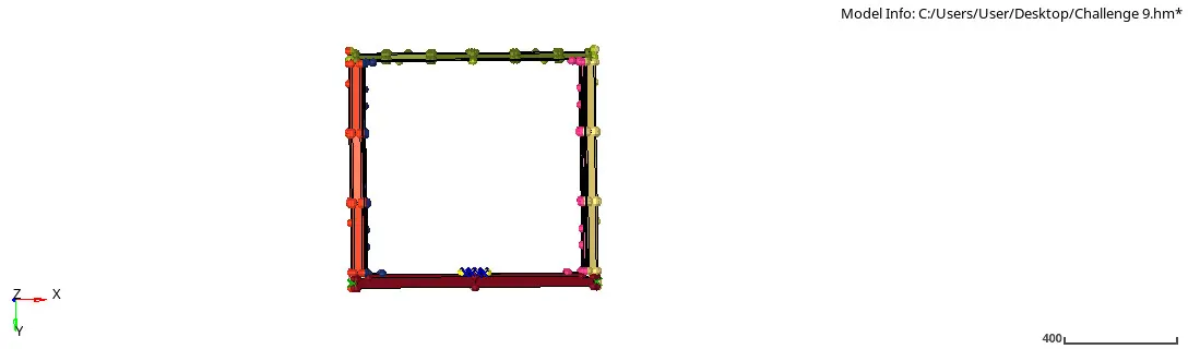
The fame assembly was on the same collectors which were shifted to different collectors in the organize. And before adding connectors all parts are given material: steel and property: Thickness 1mm and it is assigned to each individual parts.
Fig 1: Frame Assembly
| Sr.no | Connected parts | Connectors | Type |
| 1 | Right rail 2 and Front truss 1 | Seam |
Quad (angled + capped + L). |
| 2 | Left rail 2 and front truss 1 | Seam | Quad elements |
| 3 | Front truss 2, front truss 1 and right rail 1 | Spot | Weld |
| 4 | Front truss 2, Front truss 1 and left rail 1 | Seam | Hexa (Adhesive) |
| 5 | Rear truss 2 and Right rail 2 | Bolt | Bolt (general) |
| 6 | Rear truss 2 and Left rail 2 | Bolt | CBAR |
| 7 | Right rail 1 and right rail 2 | Spot | Weld (Rigid elements) |
| 8 | Left rail 1 and Left rail 2 | Spot | Weld (Spring elements) |
| 9 | Right Rail 1 and Rear truss 2 | Area | Rod |
| 10 | Left rail 1 and Right truss 2 | Spot | Spring |
| 11 | Refin plate and Front truss 2 | Spot | Bar2 |
| 12 | Front truss 2 and Right rail 1 | Spot | Rigidlnk |
| 13 | Front truss 2 and left rail 2 | Bolt | Bolt (Hinge) |
Right rail 2 and Front truss 1
Connecting right rail 2 and front truss 1 with seam connectors types given as quad ( angled + capped + L).
Command: [1D + Seam + type: seam quad (angled + capped + L) + Tolerance : 10 + weld angle : 60, cap angle: 45 + run off angle 10 + Create].
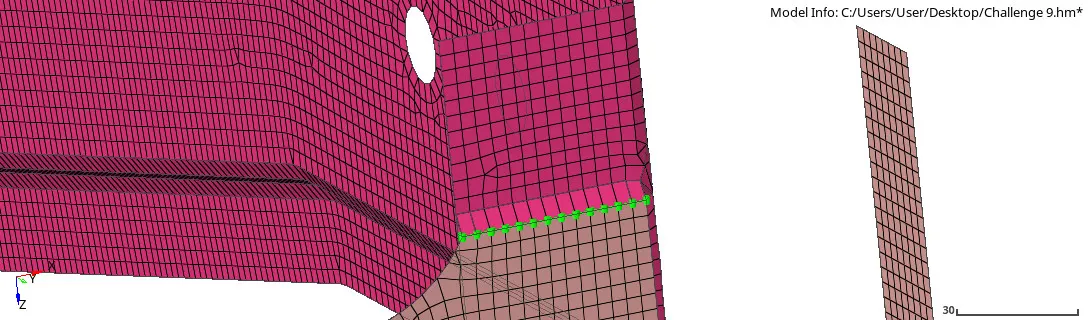
Fig 2: RR2 and FT 1 (Seam quad (A+C+L)
While connecting connectors on both parts there are some distorted elements that are fixed manually in the quality index by placing node and moving trias or remesh them by 4mm element size.
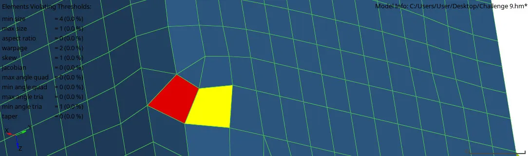
Fig 3: Fixing distorted elements (RR2 & FT1)
Left Rail 2 and Front truss 1
After adding connectors no elements where distorted.
Command: [1D + Seam + Spacing : 4 + type: seam quad + Tolerance : 10+ Create].
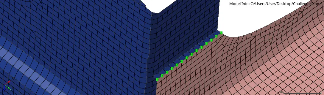
Fig 4: LR2 & FT1 Quad elements
Front truss 2, Front truss 1 and Right Rail 1
Command: [1D + Spot + type: weld + No of layers: 3, Daimeter: 5mm + Tolerance : 10+ Create].
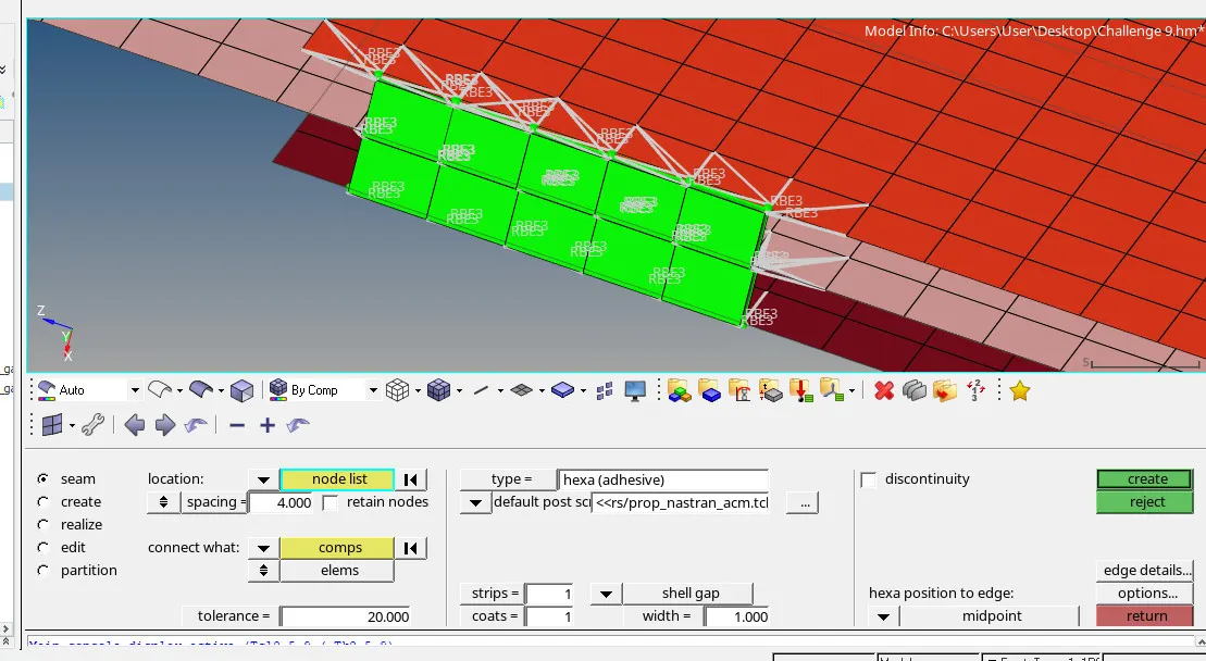
Fig 5: FT2 FT 1 & LR 1 (Hexa Adhesive)
Front truss 2, Front truss 1 and left rail 1
Command: [1D + Seam + Spacing : 4 + type: Hexa (adhesive) + Strips: 01 + Coats: 01 + Tolerance : 10+ Create].
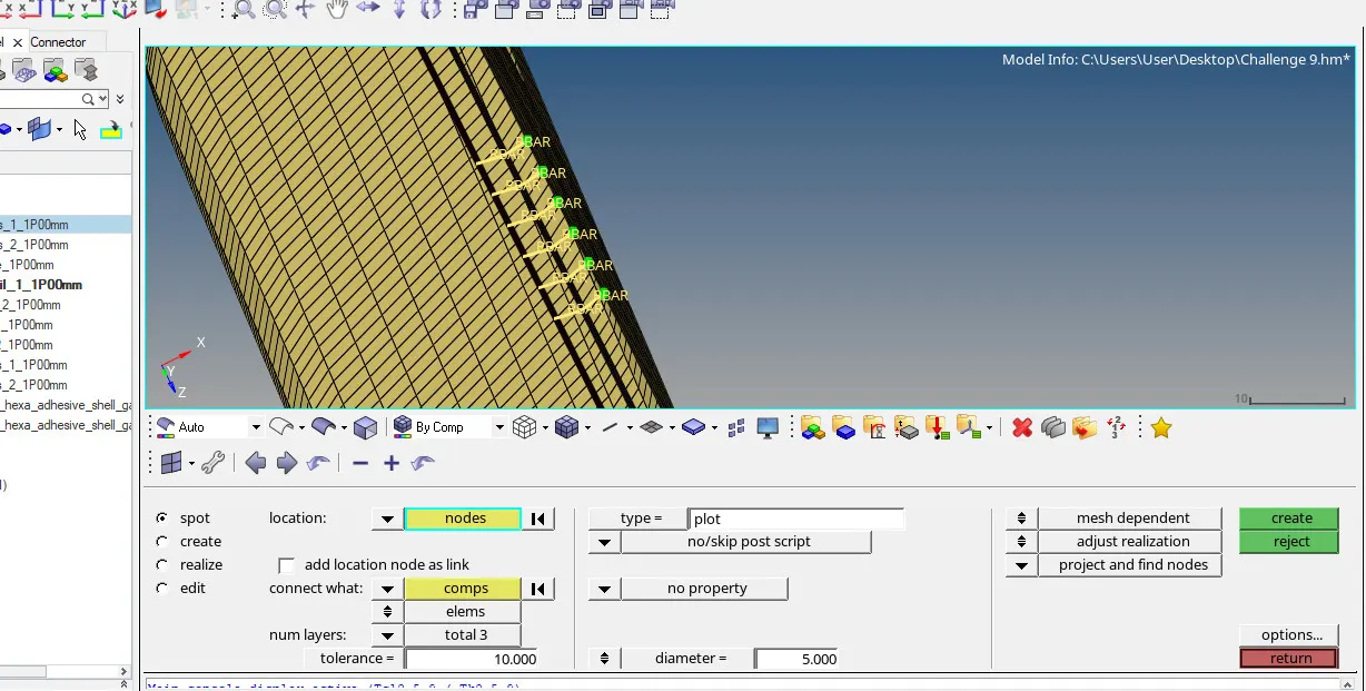
Fig 6: FT 2, FT 1 and LR 1
Rear truss 2 and Right Rail 2
Creating the connectors there are some elements which distorted because of the hole created and it is fixed by remesh and quality index.
Command: [1D + Bolt + type: bolt (general) + no of layers : 2 + Tolerance: 10 + create hole if none + create].
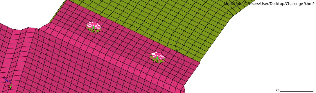
Fig 7: RT 2 and RR 2
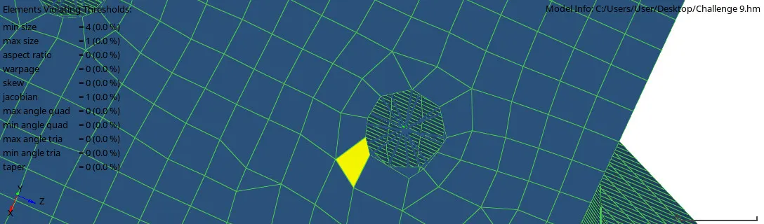
Fig 8: RT2 and RR1 distorted elements
Rear truss 2 and Left Rail 2
Command: [1D + Bolt + type: bolt (CBAR) + no of layers : 2 + Tolerance: 10 + create hole if none + create].
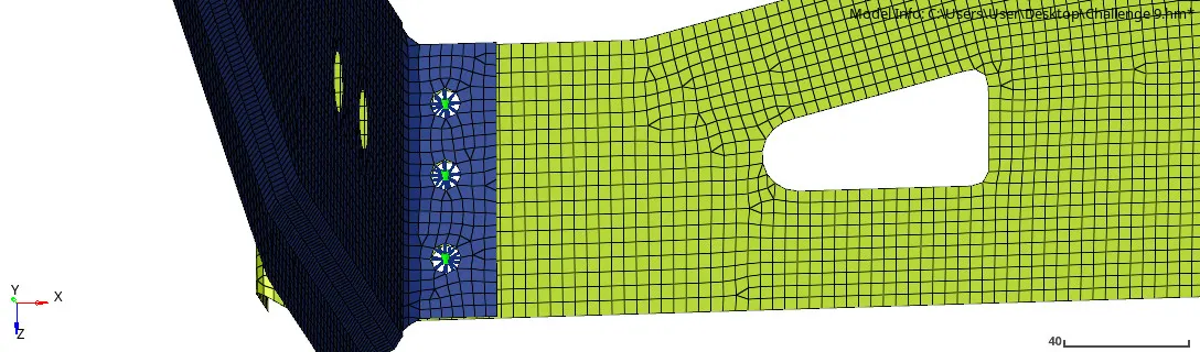
Fig 9: RT2 & LR2 (Bolt CBAR)
Right Rail 1 and Right Rail 2
Command: [1D + Type: rigid + No of layers: Total 2 + Tolerance: 10 + Diameter:1 + create].
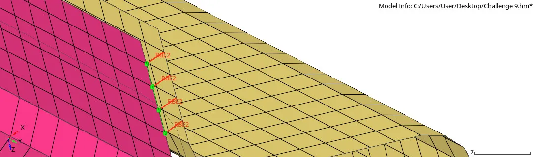
Fig 10: RR1 & RR2 Spot weld Rigid
Left Rail 1 and Left Rail 2
Command: [1D + Type: spring + No of layers: Total 2 + Tolerance: 10 + Diameter:1 + create].
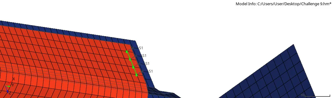
Fig 11: LR1 & LR 2 spot weld spring
Right rail 1 and Rear truss 2
Command: [1D + Type: Rod + Tolerance: 10 + Create].
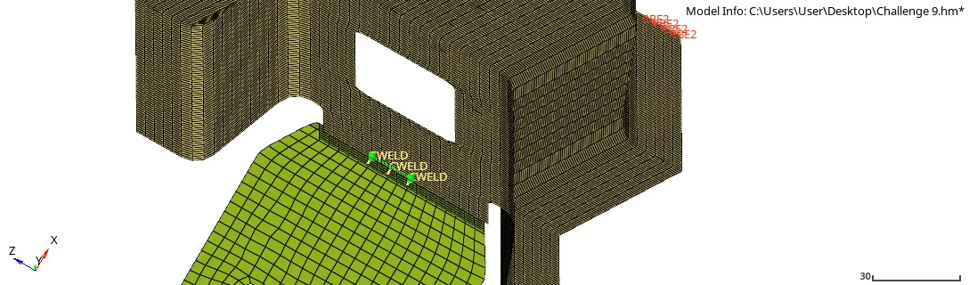
Fig 12: RR1 & RT2 (Area rod)
Left Rail 1 and Rear truss 2
Command: [1D + spot + type: Rod + Tolerance: 10 + Diameter : 1 + create]
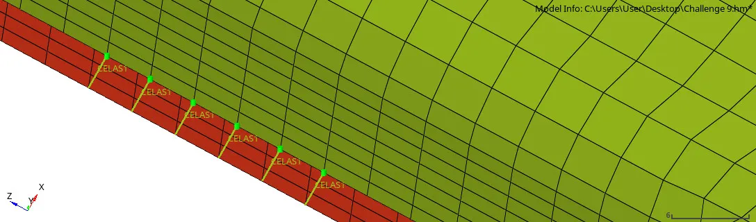
Fig 13: RT2 & LR 1 (Spot spring)
Refin Plate and Front truss 2
Command: [1D + spot + type: Bar2 + Tolerance: 10 + Diameter : 1 + create]
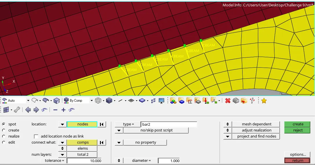
Fig 14: Refine plate & FT 2 -spot bar 2
Front truss 2 and Right Rail 1
Command: [1D + spot + type: RigidInk + Tolerance: 10 + Diameter : 1 + create]
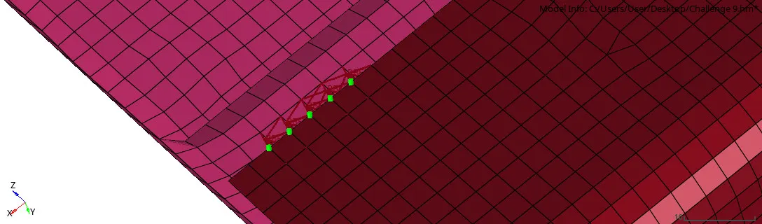
Fig 15: FT2 & RR1 (spot rigidInk)
Front Truss 2 and Left rail 2
As creating a hinge connector, the elements are got distorted and they fixed through the remesh and quality index.
Command: [ Bolt + Type: Hinge + Tolerance: 10 + create hole if none + Create].
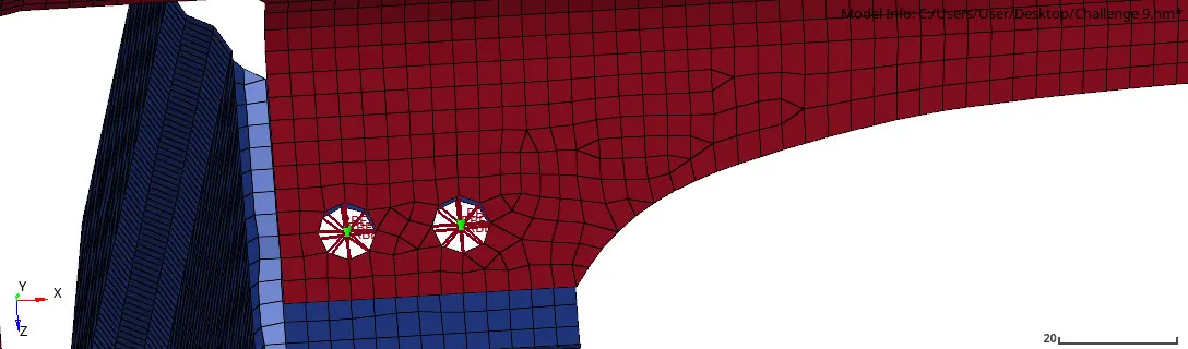
Fig 16: FT 2 & LR2 (Bolt Hinge)
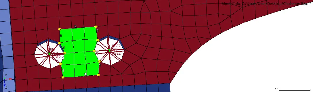
Fig 17: Fixing distorted elements FT 2 & LR2
CONCLUSION
This challenge was to get an idea of how to create 1D or 2D or 3D connectors as well spot weld as they are the same and they have different types of connectors which is created in the frame assembly.