Hypermesh Project 2: Floor Panel
OBJECTIVE:
A back wheel panel (Floor panel) component is given for mesh and to get the quality output as per given quality parameters and then assign them the thickness.
| Sr.no | Quality Criteria | Value |
| 1 | Aspect Ratio | 5 |
| 2 | Skewness | 45 |
| 3 | Warping | 15 |
| 4 | Taper | 0.5 |
| 5 | Min.Length | 2mm |
| 6 | Max.Length | 8mm |
| 7 | Min angle quad | 45 |
| 8 | Max angle quad | 135 |
| 9 | Min angle tria | 20 |
| 10 | Max angle tria | 120 |
| 11 | Tria% | 10 |
| 12 | Element size | 5mm |
Following the above quality, criteria meshing the component with 0 errors and proper mesh flow.
PROCEDURE:
The floor panel component is given for the meeting, the component has small parts that are saved in different component files which has been organized to the single whole component and remaining has been deleted.
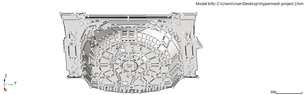
Fig 1: Floor panel
Floor panel did not have a solid part, so directly worked on the topology cleanup, the panel has many missing surfaces and or the surface are overlapping, particularly for such case a surface has been masked and checked for the proper surface deleted unwanted surface and the unmasked them.
Small circles that will not meet the quality condition, so such surfaces are deleted and the Bigg circle has some glitched to the surface so they are deleted and recreated.
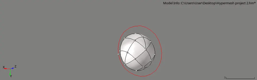
Fig 2: Deleting unwanted surface and recreate
There are some minor issues in the surface which are deleted and created the new surfaces and toggled them properly. After getting the proper surface, deleting unwanted surfaces the geometry cleanup is done on the parent component.
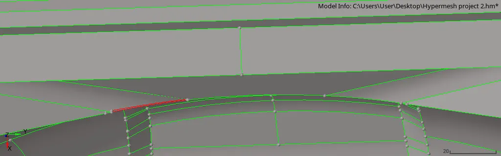
Fig 3: Geometry Cleanup
Command: [Geometry + Quick edit panel]
Completing the geometry cleanup, the floor panel has a single surface and various small parts but they attached to it, the whole component is uniform because of it the auto mid surface is done on the component.
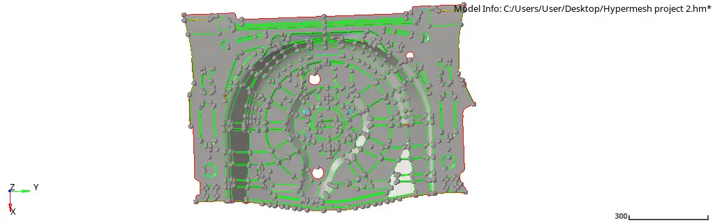
Fig 4: Mid surface
But taking the auto mid surface, some of the surfaces are having glitches which are fixed manually but at some surface fixing them was not giving proper surfaces, so the particular parts are deleted and offset them (Manual mid surface) from the parent component.
Command: [Geometry + Surface edit + offset + continuous offset (duplicate surface) + vector + offset].
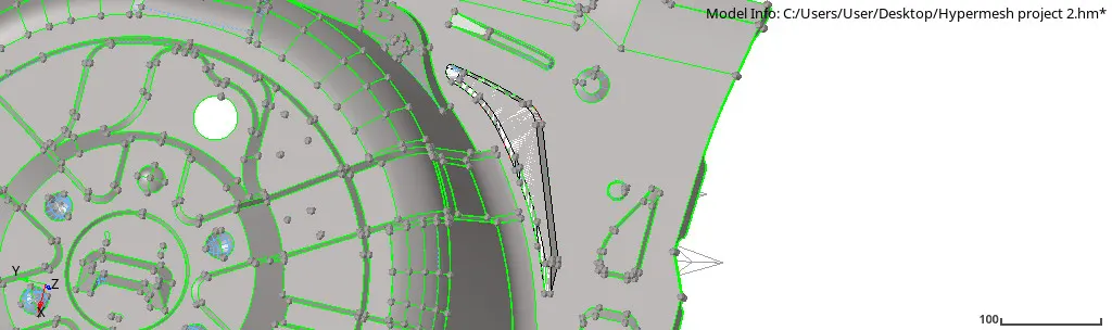
Fig 5: Manual mid surface (offset)
Fixing the surfaces glitches in the mid surface, the floor panel is the big component not and has small severe parts on them to have the proper mesh flow while meshing the component the mesh is started from the right side top part of the component with the element size 5mm and following the elements with their trias management rule and quality parameters.
Command: [2D + automesh + size + align + connectivity + mesh].
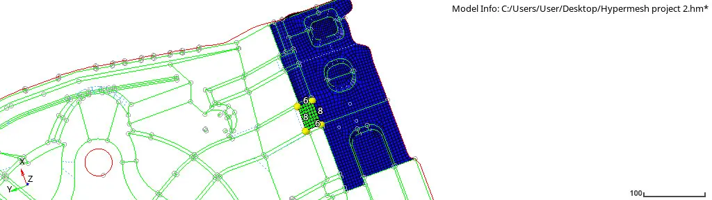
Fig 6: Meshing upper part
Meshing on the side part the trias is fixed at the corner an some of the elements that are failing for the small size and then following the mesh flow the side part is a mesh where there is a continuous surface and also it rectangular in shape so there are minimum elements that are trias are found but rather than that perfect quad elements are created.
But at corners, the trias is merging the feature line due to the small surface.
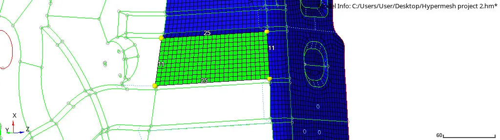
Fig 7: Meshing at the side part
In the middle part of the floor panel, there are few parts with narrow edges and the circle having the issue of warpages and the edges failing for minimum size trias, so such an issue is fixed by toggling the line at a certain distance and then joining them again.
Those warpage are fixed by giving some trias at a distance or on the particular warpage element.
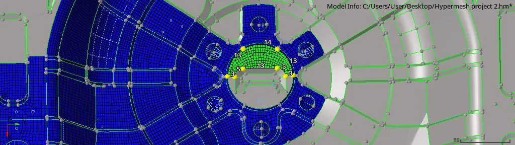
Fig 8: Mesh on the middle part
While meshing the components there are several fail elements at narrow edges or small surfaces, elements that are failing for angle quad, skewness, taper, min, and max size but fixing them as well there are unwanted trim surfaces which are toggled to have one single surface.
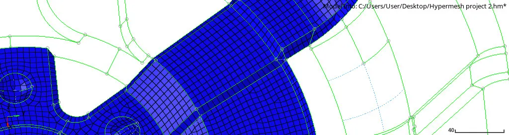
Fig 9: Toggle unwanted surface trim
Between the two surfaces at the sharp edge, there are few max angle quad or min angle quads going theme the right angle as mention in the quality parameters by placing the nodes or moving the particular node at a distance, max or min angle quad is fixed.
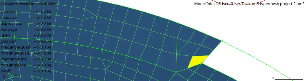
Fig 10: Fixing max angle quad
The same process is followed for the min element size and max element size they manually distance to fix these errors and the same is followed to the skewness.
Command: [Geometry + Distance + select nodes (give distance)].
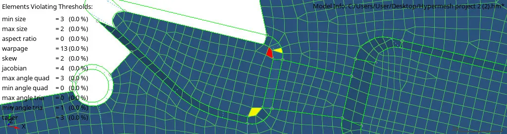
Fig 11: Fixing the max and min size element
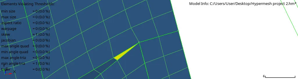
Fig 12: Fixing the skewness error
Few of the element are overlapping these elements deleted and recreated them again.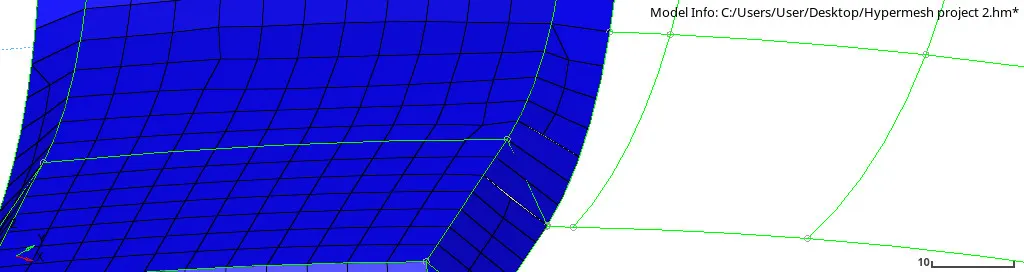
Fig 13: Delete and recreate the element
Meshing the surface after getting the mesh, checking for the edges between two surfaces, and they are fixed by given the equivalence value of 2 and the edges which are not fixed by the equivalence they are manually fixed by the replacing nodes to a particular node of other surfaces.
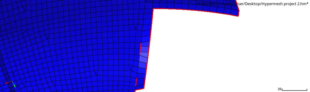
Fig 14: Fixing edges
At the circular surface after getting mesh the two trias are touching at the feature line which is split and then fixed into the quad element.
Command: [2D + Edit element + split + combine].
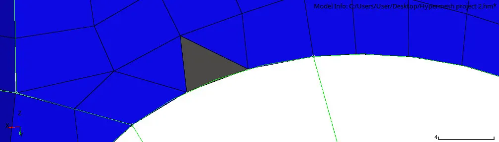
Fig 15: Split tria into the quad
Due to the surface glitches and some small surfaces, there are many warpages in this component which is fixed by the new methods checking the degree of the element and then translate the particular element by giving the value around 0.1 to 0.5, by these methods some of the warpage is fixed and some of them are by giving distance to the direction they follow or split the quad into the tria.
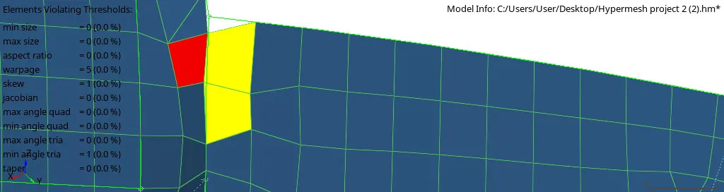
Fig 16: Fixing warpage
On the same surfaces, due to the warpage, the element is not capturing the feature line but in such a condition, it can be used for better quality output.
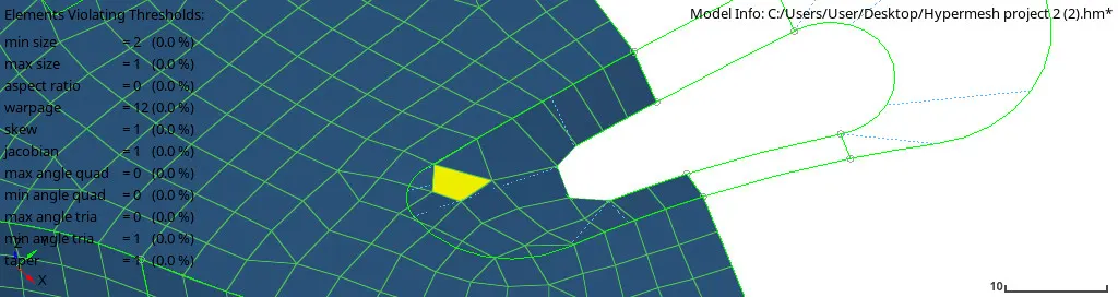
Fig 17: Elements not capturing feature line
Greeting the quality output, now a component is assigned to the thickness of the parent component which around 0.8mm, so the property is created and then thickness is given to the component.
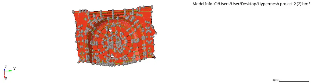
Fig 18: Assign property
RESULT:
The floor panel is the one component but has many several small parts and some surface are not offset properly in the auto or manual mid surface due to that the element is having the warpage issue but they are fixed by "translate or moving" the nodes at the given direction, other issues the edges are narrow so they are fixed by toggling the line and getting at a better distance so the element will not fail but due to the warpage fixing there is the element which is not capturing the feature line.
Overall the floor panel is capture with the quality result.
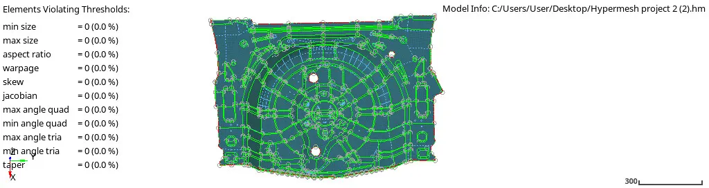
Fig 19: Quality output
CONCLUSION:
Floor panel is the different concept of hypermesh which gives detail idea about meshing and how to follow the mesh quality and flow as per the given quality parameters, also the mid surface is an important concept that understood in both automatic and manually, as checking the quality of mesh there were many warpages but they fixed by several methods, finally getting the quality output of the floor panel mesh.