Hypermesh (Project_1): Follow the quality criteria and mesh the component and assign the thickness.
Hypermesh Project_1: Follow the quality criteria and mesh the component and assign the thickness.
OBJECTIVE:
The Sidedoor component is given for extracting the midsurface manually or automatic and then follow the quality parameters to get quality mesh and then assign the thickness to the given component.
| Sr.No | Quality Criteria | Value |
| 1 | Aspect ratio | 5 |
| 2 | Skewness | 45 |
| 3 | Warping | 15 |
| 4 | Taper | 0.5 |
| 5 | Min. Length | 2mm |
| 6 | Max.Length | 6mm |
| 7 | Min angle quad | 45 |
| 8 | Max angle quad | 135 |
| 9 | Min angle tria | 20 |
| 10 | Max angle tria | 120 |
| 11 | Tria % | 10 |
| 12 | Element size | 4mm |
Follow the above quality criteria and mesh the component by giving element size value to obtain the fine mesh.
PROCEDURE:
The side door component is given for meshing, the component has one whole part with the unconnected part is been separated to the different destination collector.
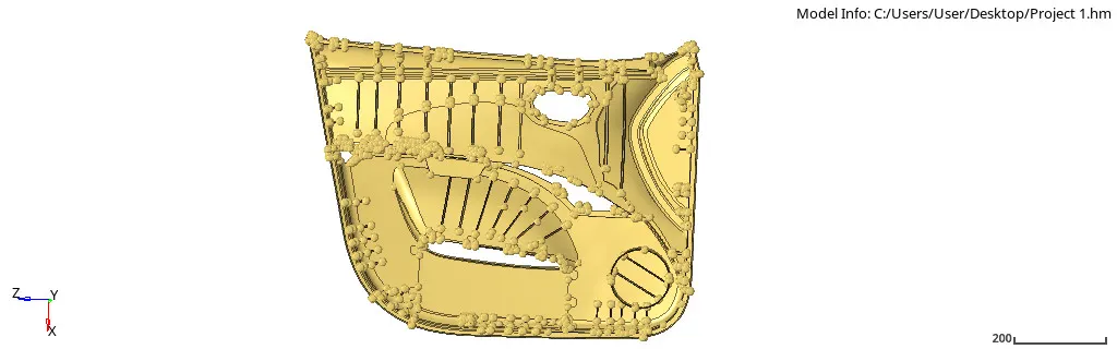
Fig:1: Side door
Command: [Tool + Organize + Collector + destination component].
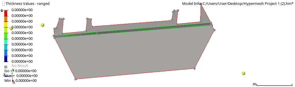
Fig 2: Component 2
The component has done some geometry cleanup where the glitches are found on the surface, toggling the lines to avoid minimum size length of the surface other than few surfaces were not properly created in the CAD file that surfaces, where deleted and recreated by following the filler surface or spline or ruled command in the surface tool.
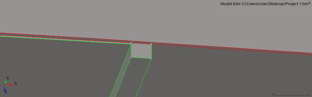
Fig 3: Geometry cleanup Parent comp
The fillets below 0.5mm to 5mm have been defeature to capture the proper element length and to avoid fail elements.
Command: [Geometry + defeature + surf fillets + find fillets ( max radius: 0.5mm to min radius: 5mm) + Find + remove].
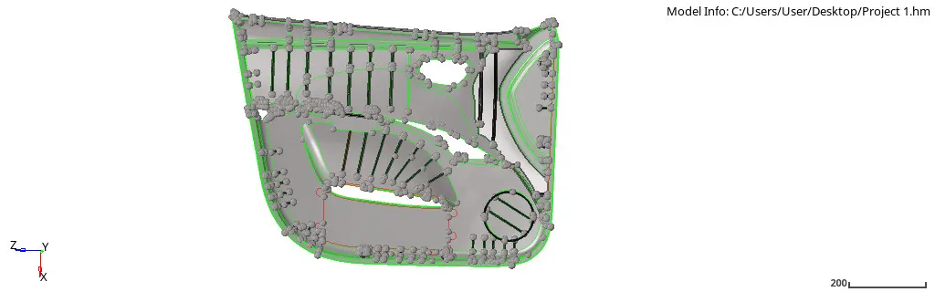
Fig 4: Defeature fillet
Completing the geometry cleanup on the component, it is been extracted for the mid surface automatic, but obtaining the mid surface automatically, it found many surface defects or missing surfaces, also the ribs are not properly extracted.
Undeleted fillets on the ribs have been deleted manually by selecting the specific surfaces.
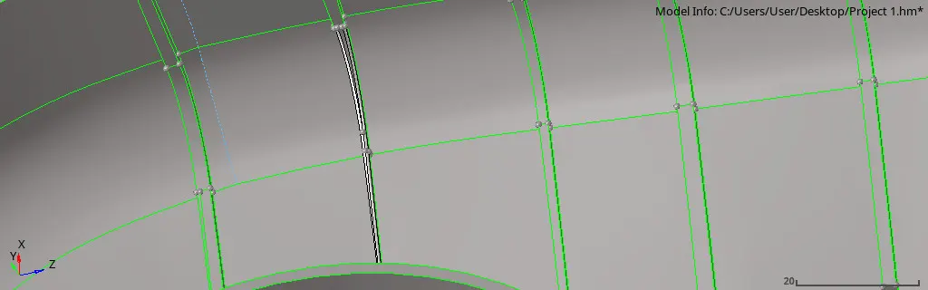
Fig 5: Undeleted fillet deleting manually
To get the proper mid surface, the manual mid surface extracted to get a general idea about the mid surface but manually also found many glitches and it was difficult to fix those and also it was time-consuming, so the manual mid surface is not deleted and kept for he reference and worked on the auto mid surface.
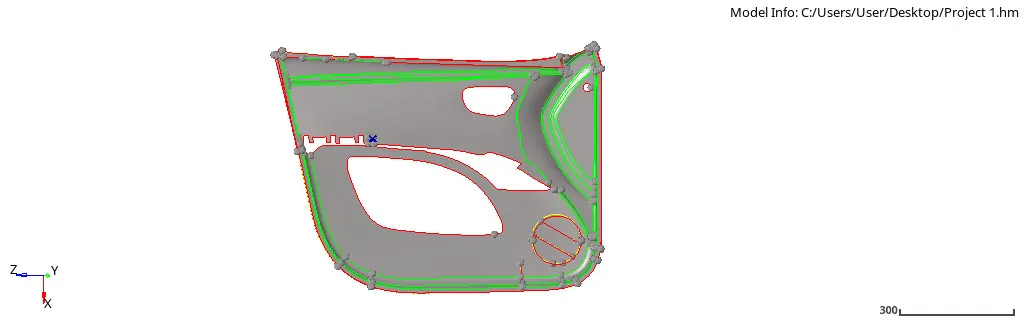
Fig 6: Manual mid-surface
The manual mid surface is used for reference and organizes proper surfaces to auto midsurface, fillets which were not captured properly were manually extracted.
Command: [Offset + discontionus offset + surf (duplicate) + vector + offset] or [Midsurface + final edit tools + side 1 surf and side 2 surf].
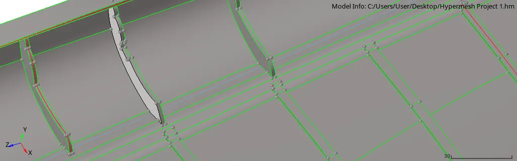
Fig 7: Ribs mid surf manually
The ribs are extracted manually but for connectivity, they are extended to surfaces but while doing the extend the ribs some of them are properly got extended but in some cases where they are connecting to the multiple surfaces, because of those ribs the surfaces are been deformed.
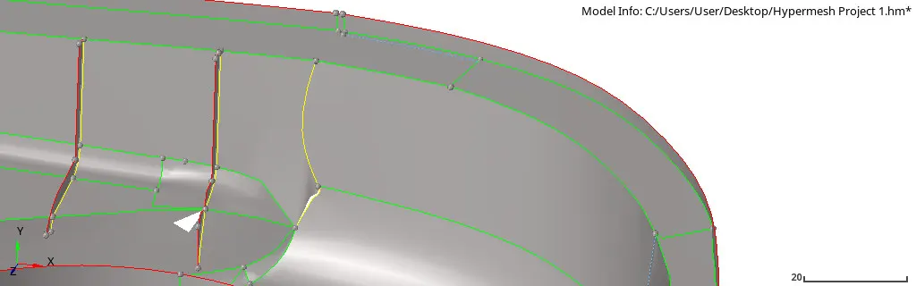
Fig 8: Deform ribs surfaces
So those ribs are kept apart from the surface and to have connectivity for those elements the edges are imprinted on the surfaces.
Command: [ Surf edit + trim with lines + cut line (surf) + drag cut line + trim].
Completing the surfaces glitch, extracting the ribs properly, or give them a proper space that is not extended properly and obtain the mid surface for the meshing part.
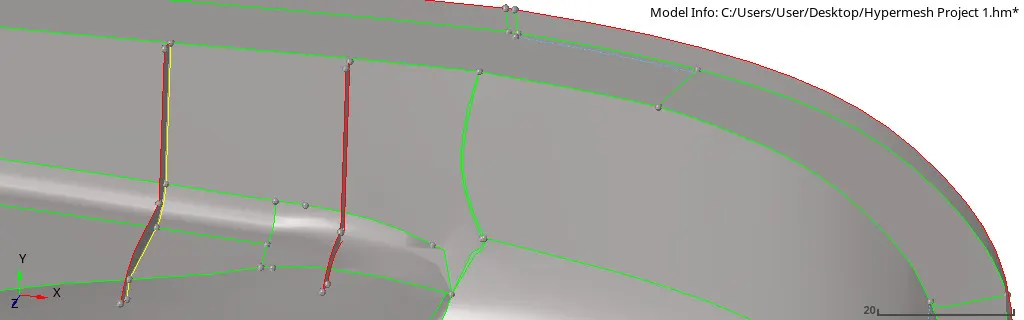
Fig 9: Ribs not extended
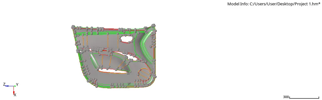
Fig 10: Auto mid surface
Extracting the mid surface and fixing the issues in the surfaces it is meshed by a 4mm size element on the mountain part by splitting the surface in the rectangular portion to have minimum trias.
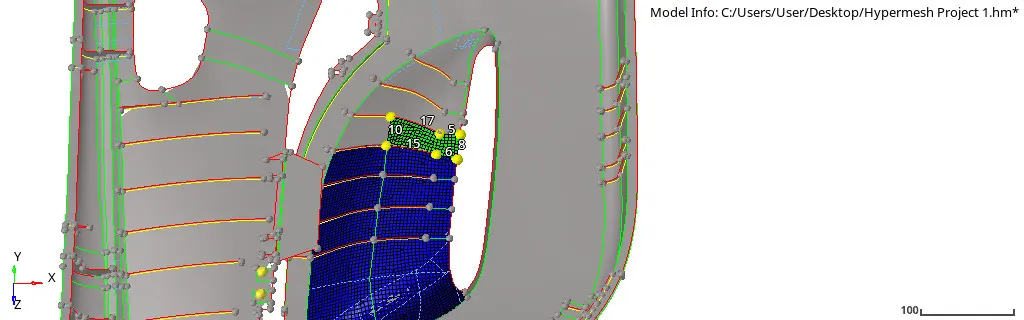
Fig 11: Mesh on the mountain surface
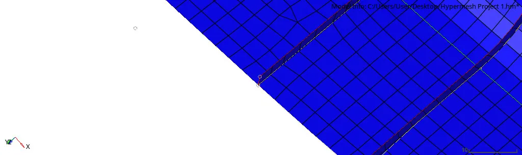
Fig 12: Splitting surfaces
Trias is minimized where ever possible and obtain max quads elements without the rotation quads. The elements that were not capturing the feature line properly they are selected by line needs and place them people to capture the mid surface feature line.
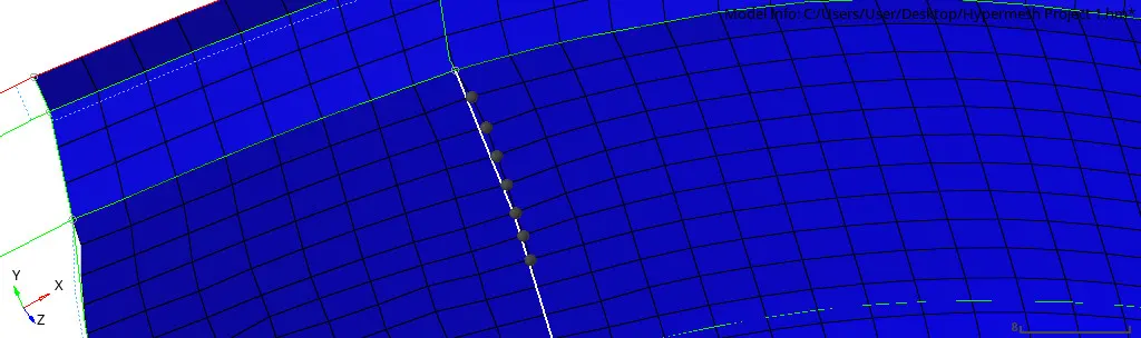
Fig 13: Capturing Feature line
Elements failing for minimum size length that has been distanced manually to fix the errors and obtain the quality value. Also, the elements on the corners are avoided the are moved at a specific distance. On the same surfaces the opposite trias is avoided but the surface such as curve it is not possible to fix those trias and also they are accepted under such conditions
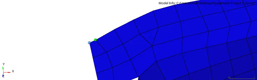
Fig 14: Increasing element length manually
The cylinder part upper part inside surface and the outside surfaces have meshed and they are connected properly by checking the edges and fixing those edge by giving equivalence value of 2 and unconnected elements are connected manually by replacing the nodes.
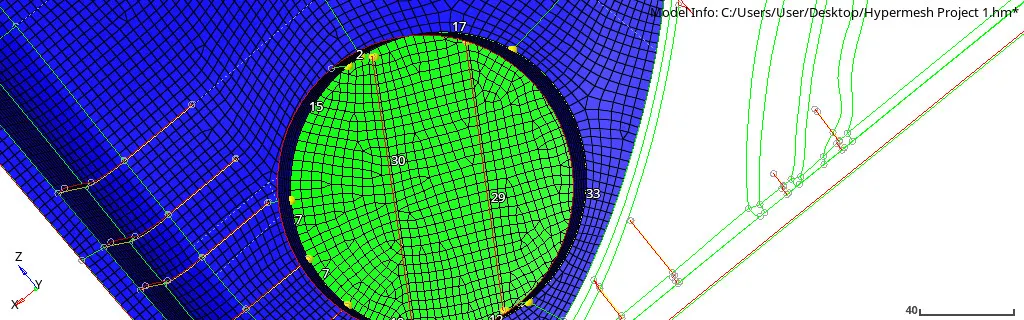
Fig 15: Meshing cylinder part
The elements are merging on one another that is being deleted and new elements are created to give mesh flow.
Command: [2D + edit element + create + selecting nodes].
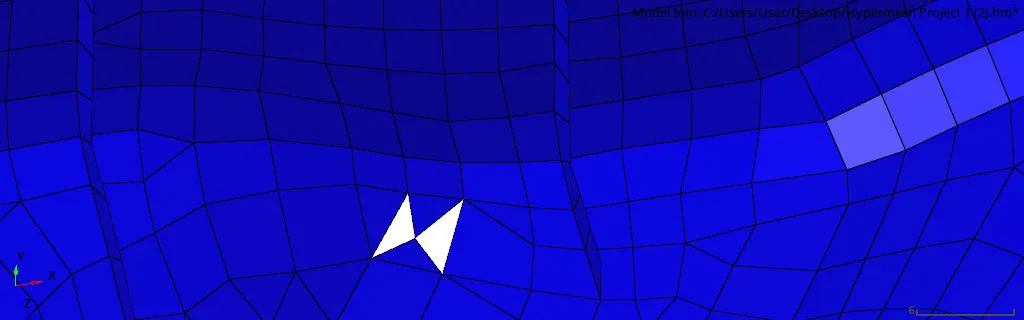
Fig 16: Delete and recreate the element
Ribs are meshed and being connected to the surface mesh but the ribs which were not connected to mid surface in that case elements have no connectivity after the meshing. Those ribs are being replaced manually to the surface elements to have connectivity between them.
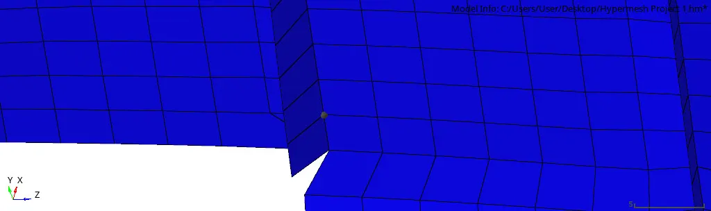
Fig 17: Ribs placing nodes
Some of the elements of the ribs are failing for minimum size due to the surface of the ribs has small distance those are fixed by given them distance manually which is effecting to capture the feature line but in this scenario, it could be avoided for failing elements.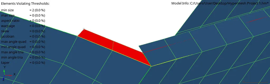
Fig 18: Ribs failing elements
While meshing on the large component and varying the surface difference there is some connectivity issue the elements are not connected to each other, so they are checked for any free edges and connected them by giving equivalence value of 2 maximum and there fixed for connectivity but some elements also not being connected and they are replaced manually.
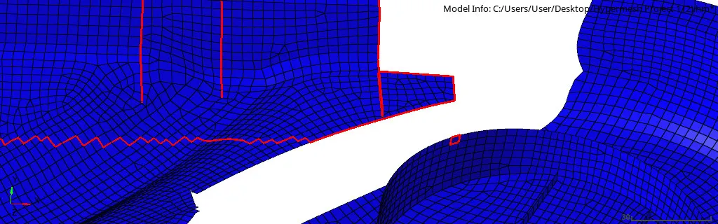
Fig 19:Fixing edges
After correcting the elements and fixing their edges they are being smooth to have proper mesh flow. Smoothing is done by iteration value of 1.
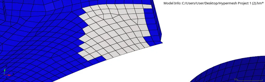
Fig 20: Smoothing elements
After meshing the surface the elements are checked for the quality index, some of the elements are failing for the minimum and maximum size they are fixed by placing the nodes, and some of them are fixed by element optimization. Other elements are failing for the min and max angle train or quad they are also replaced by giving place node commands the same process is done of other failing elements by the cleanup tool.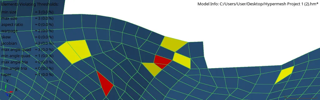
Fig 21: Max and min errors
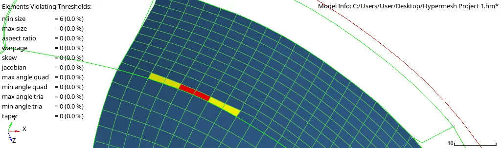
Fig 22: Placing min elements
The other failing elements such as the warpage are fixed by the edit the elements (split the elements) into the trias and being separated apart to consider the trias management rule.
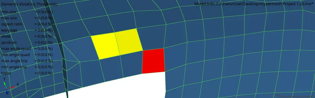
Fig 23: Fixing Warpage
Fixing the errors and getting the mesh to flow properly the whole component is messed by the given quality aspect followed the quality parameters, and then assigning the thickness respective to the thickness of component for that duplicate component created and organize to tho their component file.
Command: [Create + Property ].
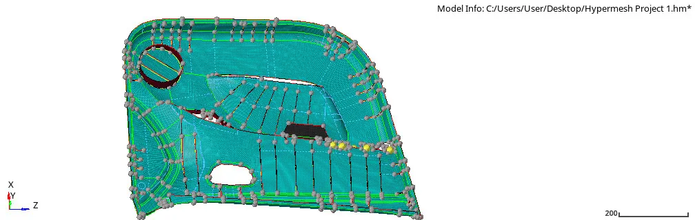
Fig 24: Property Assigned
RESULT:
The side door components are meshed by the value of 4mm and then followed the quality parameters, to obtain the quality output of the elements. The side door is achieved by the given value and has proper mesh flow.
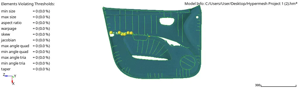
Fig 25: Quality output
CONCLUSION:
The side door component is given for mesh by the respective quality values that are followed and then the same component has assigned to the thickness of 1mm.