ANSA Week 3 Challenge
AIM
To extract the mid surface and then mesh the component with given quality parameters and assign the thickness on a hood component.
OBJECTIVE
Hood component is given with five different parts:
- Hatch.
- Left and right Hinge.
- Inner panel.
- Outer panel.
To assign the property on each part with their parent component thickness and then mesh the component with target size 5mm and as per given quality parameters.
| Sr. No | Quality Criteria | Value |
| 1 | Target/Average Length | 5 |
| 2 | Minimum Length | 2 |
| 3 | Maximum Length | 7 |
| 4 | Aspect | 3 |
| 5 | Warpage | 15 |
| 6 | Skewness | 45 |
| 7 | Jacobian | 0.7 |
| 8 | Minimum quad angle | 45 |
| 9 | Maximum quad angle | 135 |
| 10 | Minimum angle tria | 30 |
| 11 | Maximum angle tria | 120 |
| 12 | Tria percentage | 15 |
PROCEDURE
The hood component geometry is open in the Ansa for Meshing, the file is open with STP format, The hood component has four different parts which are locked differently to see each part individually to extract the middle surface and mesh the component.
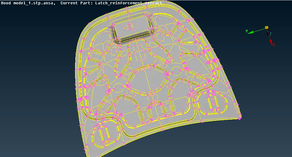
Fig 1: Hood panel
Command: [ Inot + Neighb (All) + Selecting all faces + create store lock (For all components)].
For Topology checking the unnecessary cons in parent component the deform faces, cracks in the geometry. After checking the errors in checks that can be fixed auto but executing the auto-fix option after fix the errors need to check any surface changes in the component.
Command: [Checks + Geometry + except single cons check all other entities + execute + Auto fix].
Middle surface: The middle surface is the middle part of the parent component which has two surfaces by measuring the thickness of the component, selecting a single face, and extract at the mid-value of the component.
Hood panel has for five parts in which three of them have a similar thickness of 1.2mm and the remaining two-part outer and inner panel 0.75mm. So the hood component is non-linear.
To extract the middle surface of the component can be done manually or Auto option. The Right hinge, Left hinge, and Hatch extracted manually by selecting the faces and then taking the middle surface by the value of 0.6mm.
Command: [Offset + Faces + Select the single face of the component + Extract].
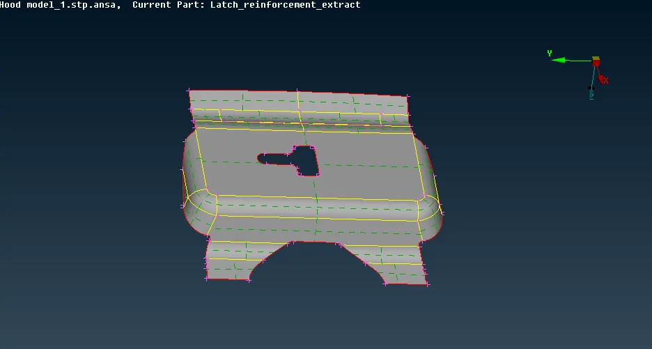
Fig 2: Manual Mid surface
And the Outer and inner panel is middle surface extracted in auto option by selecting the entity and then giving he middle value of component 0.375mm
Command: [Mid surface + skin+ select component + Checking the green, red and blue on the surface + Extract mid surface]
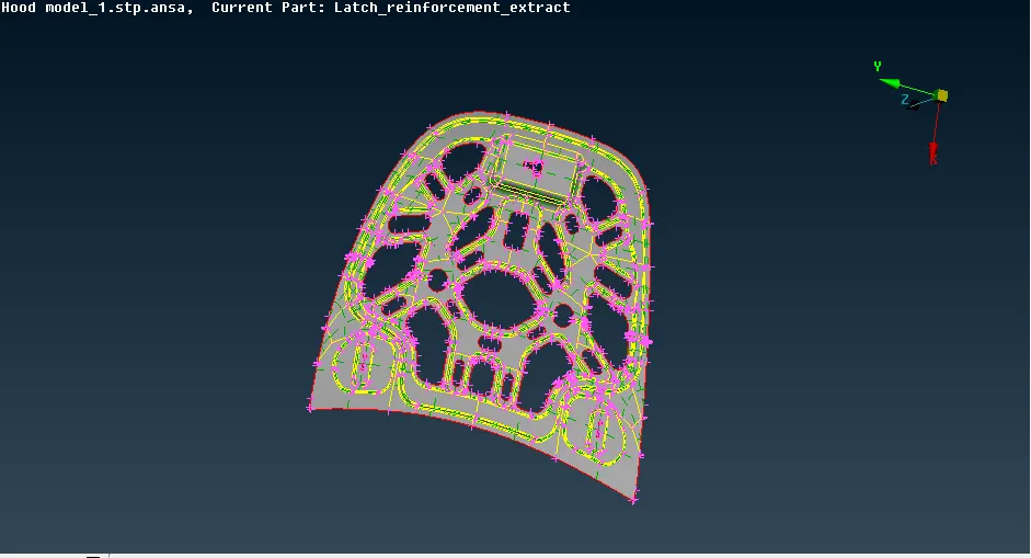
Fig 3: Auto mid surface
Extracting the mid surface of each part, the component is assigned to the property with their individual thickness as the three parts have a similar thickness so they are assigned to the 1.2 mm value and inner panel and outer panel at 0.75mm value.
The property is assigned in the properties panel by creating new property and giving T to the component as per their particular value.
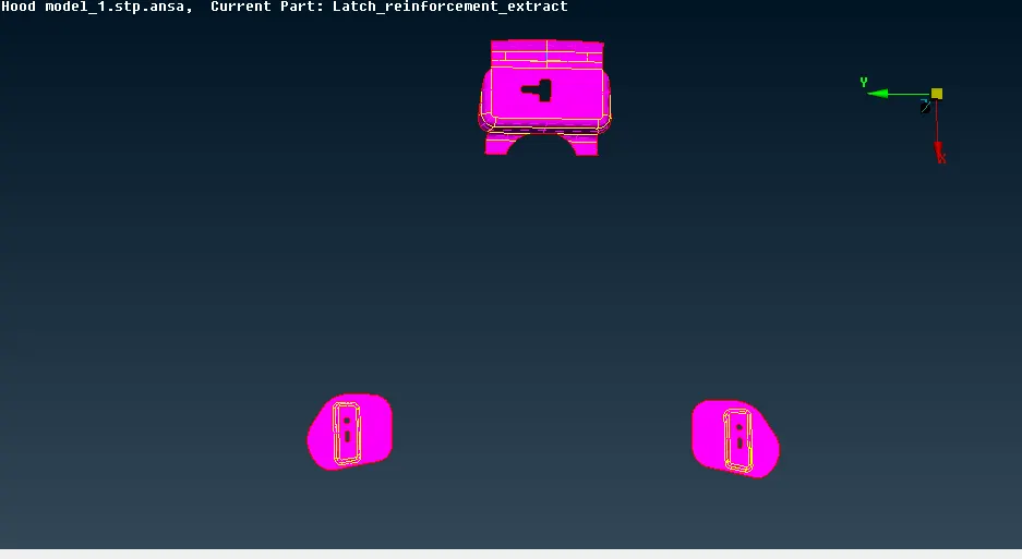
Fig 4: Property to Latch and Hinge
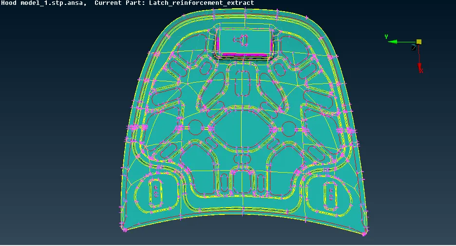
Fig 5: Property to Inner and Outer panel
After extracting the middle surface and assigning the thickness, now a component is meshed by particular process before meshing to understand the meshing and process to adapt it.
Meshing: It is the finite element analysis process that divides the component at finite surface by giving the nodes and the element to solve for mathematical equations in analysis software.
To adapt mesh the component changed to the length of the target element size of meshing which 5mm. and the quality parameters value is given in the quality parameter panel. For meshing the Best option is used as new to the ANSA, to get best practices as a new start.
First, the hatch is meshed with given element size, to have the fines mesh flow the part is a divide in smaller rectangular size by giving the cut option and then selecting the particular surface for meshing.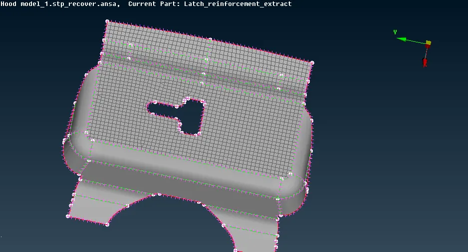
Fig 6: Mesh on Hatch
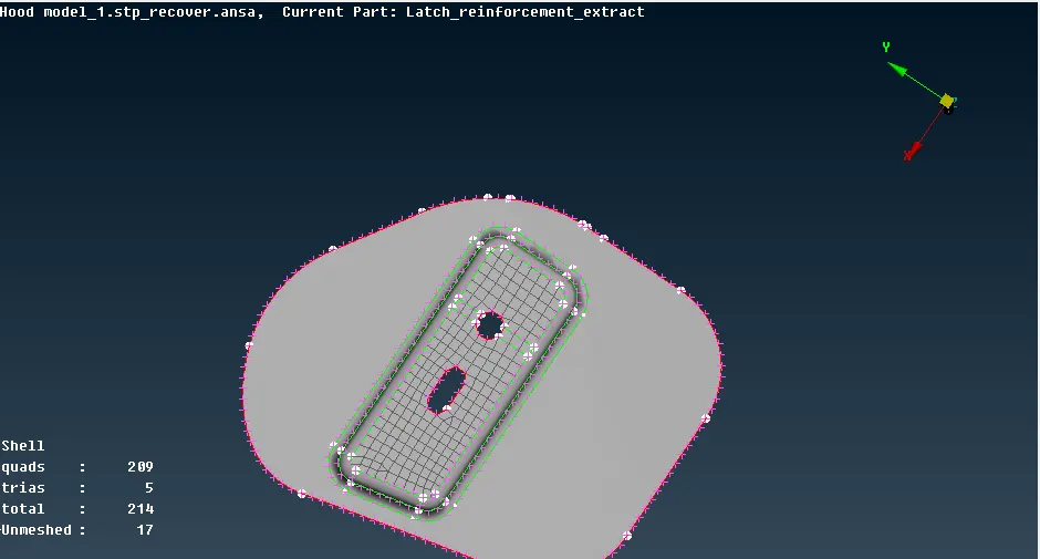
Fig 7: Mesh on Hinge
Similar steps are followed for right and left hinge, as the outer panel is the big part is has small fillet which fails for minimum element size so that fillet is a defeature by removing the cons on fillet giving the cut on the middle of the fillet. In the inner panel, the surface is varying so to obtain the proper mesh flow the component removed with unnecessary cons and giving the proper cut to the fillet part and other surfaces.
Also, the outer and inner panel has asymmetric surface so obtain mesh fast, the half surface is deleted and the mesh is done.
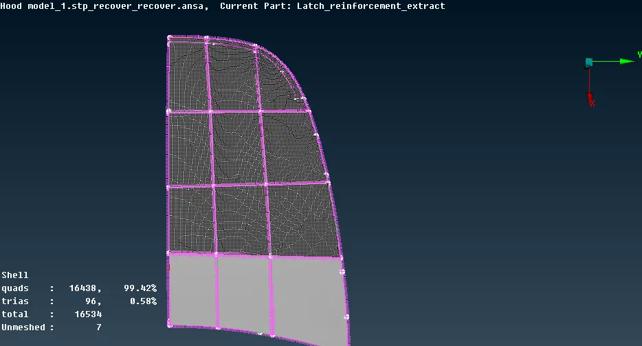
Fig 8: Outer panel mesh
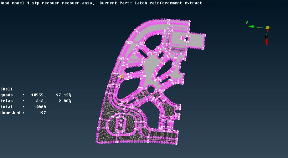
Fig 9: Mesh on Inner panel
While meshing the component has failing elements for several criteria such as skewness, warpages, minimum and maximum length, max, and min quad angle. To fix them manually they are obtained from the mesh panel, the are many methods to fix them.
After giving mesh to the component the mesh flow doesn't get proper, so it is reconstructed again to obtain proper mesh flow but to have perfect mesh as per meshing criteria there are some rules that should be followed after meshing the component, Once we meshed the component there are some trias and quads elements the quads are fine for mesh except rotational quads and trias has some rules, so that need to be followed.
Trias management rule:
- Back to back trias.
- Opposite trias.
- Trias on edges.
- Trias on circle edges.
- Trias in three directions.
- Reduce trias.
- Trias on fillet, if possible.
Failed elements and Fixing them
The elements are failing for minimum and maximum length they are fixed by re-meshing it or moving them in a particular direction, this option clears the failing criteria.
Trias is fixed by splitting them and pasting at a particular area to have proper mesh flow.
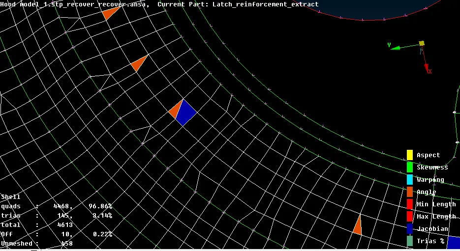
Fig 10: Fixing jacobian and angle
The sharp edges (Elements at edges are moved at a particular distance or reconstructed them again). The smooth options help to achieve proper mesh flow.
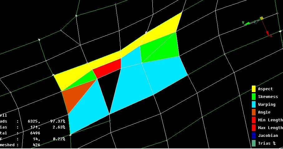
Fig 11: Fixing sharp edges
The overlapping elements or elements which are not created properly are deleted and then recreated to have have mesh and the region is smooth again.
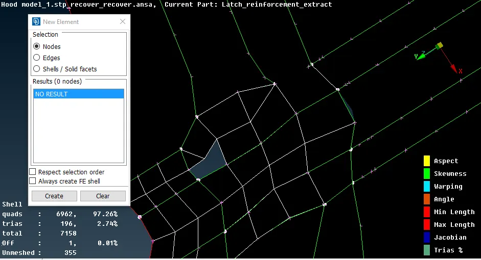
Fig 12: Deleting and recreating element
Back to back trias are fixed by updating the option of splitting them a particular distance.
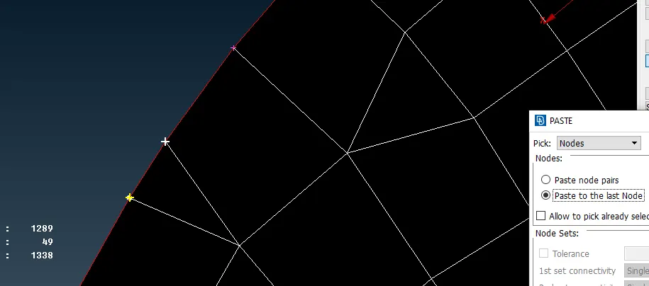
Fig 13: Paste two nodes.
RESULTS
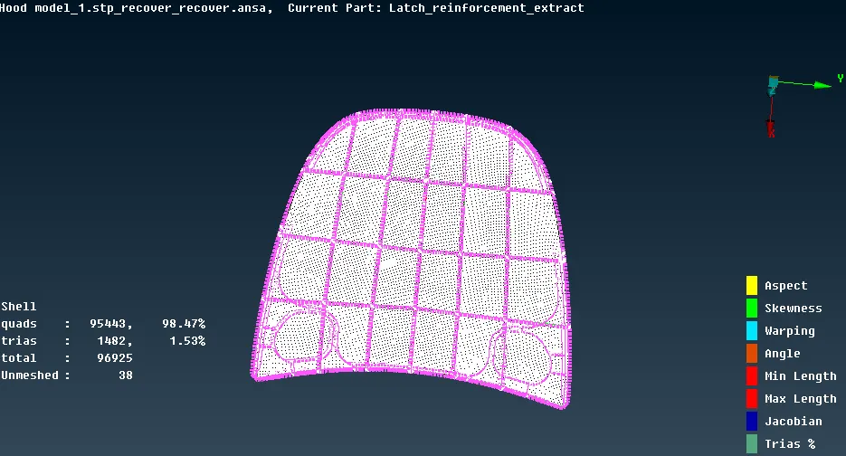
The mesh is obtained significantly on each component fixing them by using several options in the mesh panel. as the symmetric surfaces are deleted and meshed on single surfaces but the as a result on the outer panel the mesh is not connected as it used with auto paste option but it not working as well.
But the elements that are failing are fixed and the quality result is obtained with less trias percentage of approx 1.53% and quad approx 98.47%.
CONCLUSION
The hood component is extracted with with mid surface and assigned to the thickness of parent component and then meshed with given quality parameters and element size with then given value and criteria fine mesh flow is achieved