Hypermesh Challenge_ 4 (Create 1D elements on the following component with given cross-section and DOF)
Challenge 4 - Create 1D elements on the following component with given cross-section and DOF
OBJECTIVE: To create the different types of 1D elements such as ROD, BEAM, and BAR and also to apply mass magnitude on the following component with given cross-section dimension and Degree of Freedom (DOF).
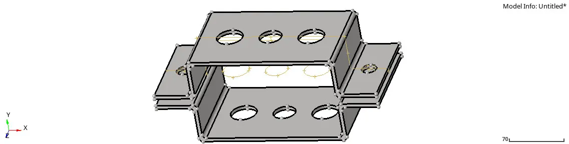
Img 1: Create 1D elements on the given Geometry
PROCEDURE:
- To start with importing geometry as the IGES file.
- Create the midsurface on the upper geometry by the following command "Geometry + mid-surface + select the surface on the given geometry + Extract
- The same procedure will follow for the next geometry to create midsurface by following the same command.
- Rename both midsurface with Bracket_1 and Bracket_2 and change the color as well.
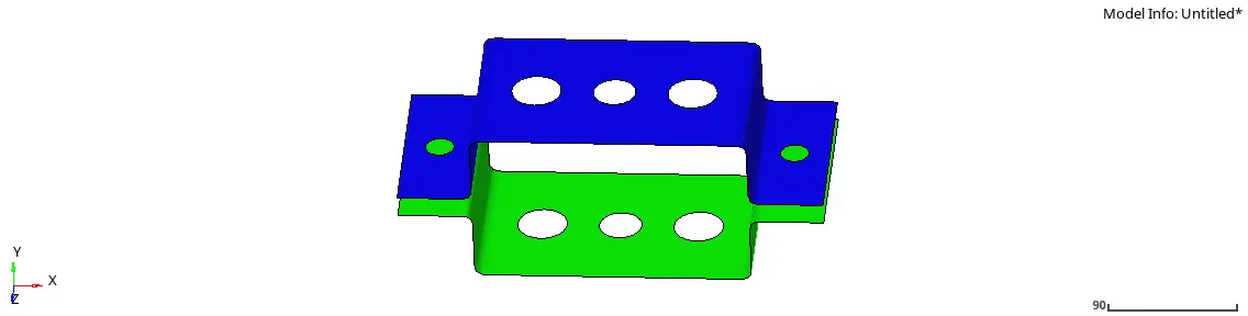
Img 2: Midsurface of the bracket
- Now deleting the solid part and wireframe of the bracket by following command "Delete + Solids + All + Delete entity" Also to delete wireframe command "Delete + lines+ All + delete entity".
- Also delete both solid part and wireframe from section component, so after deleting bracket left with midsurface.
- For 3D representation assign to thickness, to assign it to create a material
- Material 1: Steel
- To give thickness to both brackets create a Properties "Bracket_1 and Bracket_2" and assign both Properties to the midsurface.
- Property 1: Thickness = 2.0mm, Material = Steel and Card Image = PSHELL.
- Property 2: Thickness = 2.5mm, Material= Steel and Card Image = PSHELL.
- Assign Material to the respective property with a specific component such as Bracket_1 with property_1 and material_1 and Bracket_2 with property_2 and material_2.
- Now perform 2D mesh, but before meshing, give a washer split at 4 mm and then perform 2D mesh with element size= 9 and element type= mixed, select the surface and do Mesh.
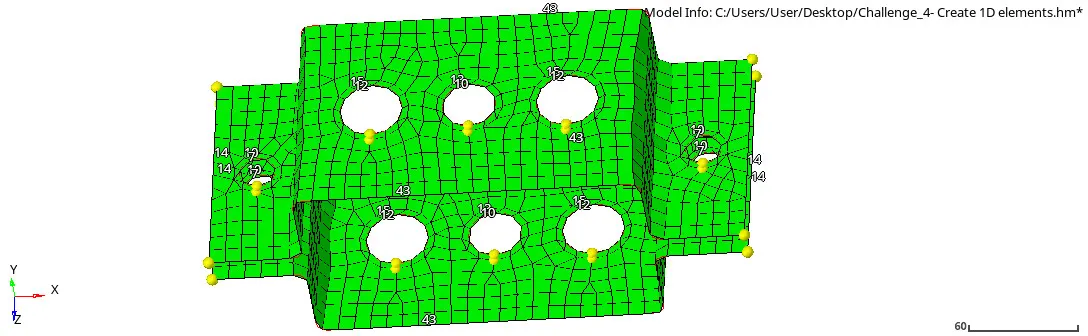
Img 3: 2D mesh on the Bracket
- Meshing was performed on the geometry because to have the nodes before creating the 1D elements.
- "To create 1D elements on the bracket" The first element to create is rigid (RBE2) link on (a),(e), and (d) section with only transitional Degree of Freedom (DOF) on (a), and all DOF on (e) and (d). Whereas (RBE3) link on (b) and (c) with all DOF on (b) and with (x) and (y) DOF on (c).
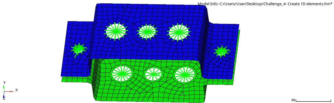
Img 4: RBE2 and RBE3 element
- Difference between REB2 and RBE3 element:-
Sr.no RBE2 RBE3 1 Infinite stiffness, which never bends, never rotate, and never move But this element can be moved wherever possible 2 Distribute load equally not each and every element irrespective to their position and distance of independent node Load distribution is different and not uniform - Rod element Dimension (Box)
Dimension (a) 12mm Dimension (b) 10mm Thickness (t) 0.75mm
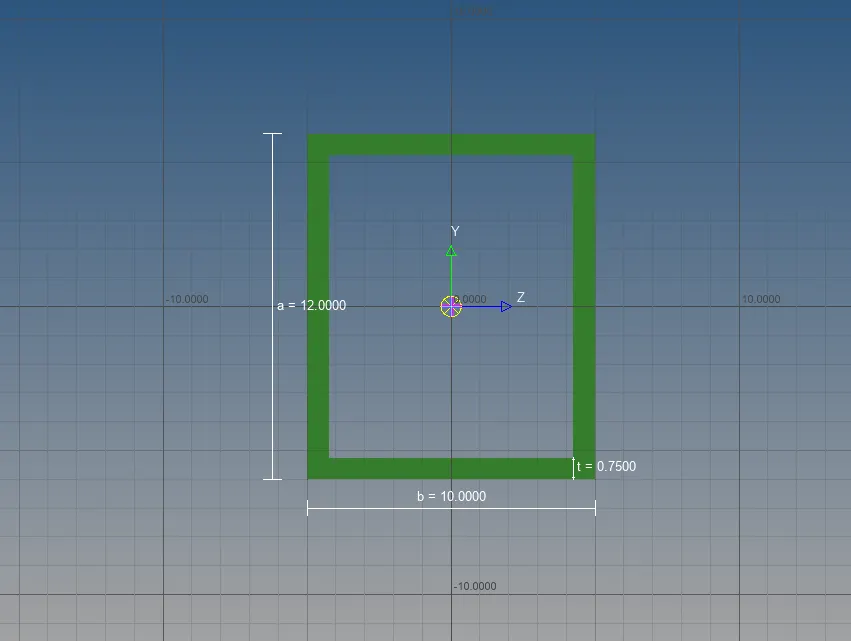
Img 5: Rod element
- Beam element Dimension (I section)
-
Dimension (a) 8mm Dimension (b) 10mm Dimension (C) 8.5mm Thickness (t1) 0.75mm Thickness (t2) 0.6mm Thickness (t3) 0.6mm
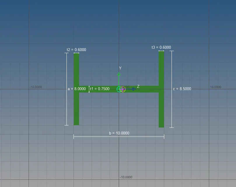
Img 6: Beam element
- Bar element Dimension (Cross-section)
Dimension (DIM1) 5mm Thickness (DIM2) 1.2mm Dimension (DIm3) 10mm Thickness (DIM4) 1.2mm
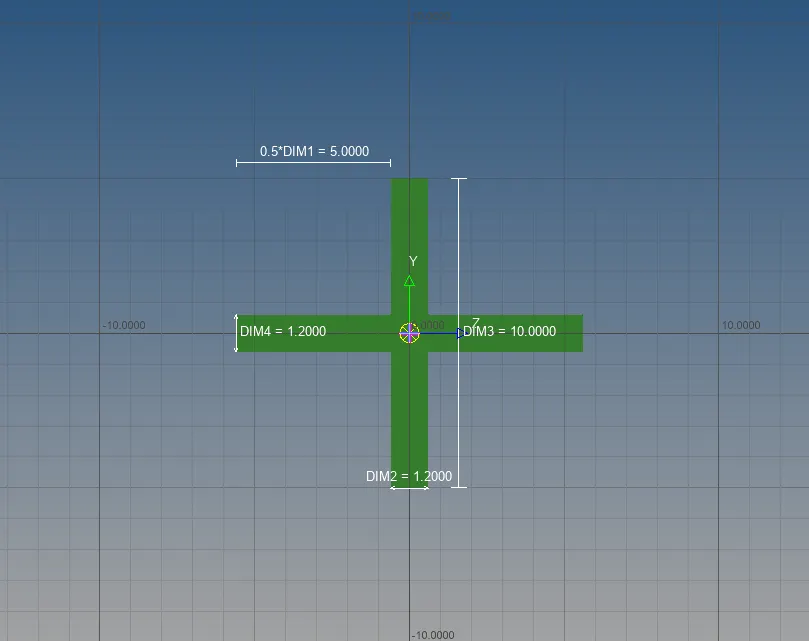
Img 7: Bar element
- Difference between Bar, Rod, and Beam
-
BAR ROD BEAM All 6 Degree of Freedom (DOF) will be used and for symmetrical section Tension and compression, for certain software for rotation It is similar to the bar but used for Asymmetrical Section - Now to create rod, beam, and bar with respective to RBE2 and RBE3 link on the given (a), (b), and (c) section but without assigning to the cross-section.
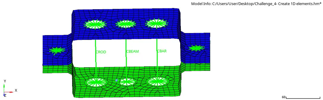
Img 8: ROD, BEAM, and BAR without assign
- Create the property on each element for Rod, Beam, and Bar because all three components are in Bracket 2, so they will have different properties.
ROD Card Image - PROD Beam section - (10) Rod
BEAM Card Image - RBEAM Beam section - (11) Beam BAR Card Image - PBAR Beam section - (13) Bar - Updating the property to the respective component, for Rod and Bar Command "Bar + select elements + select properties and element type to each of them + vector direction + update" again select property + update.
- Now the properties are assigned to get component with respect to their cross-section but to get a visualized cross-section of each component, give the command "1D detailed element representation".
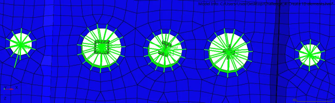
Img 9: Cross-section of 3 components (1)
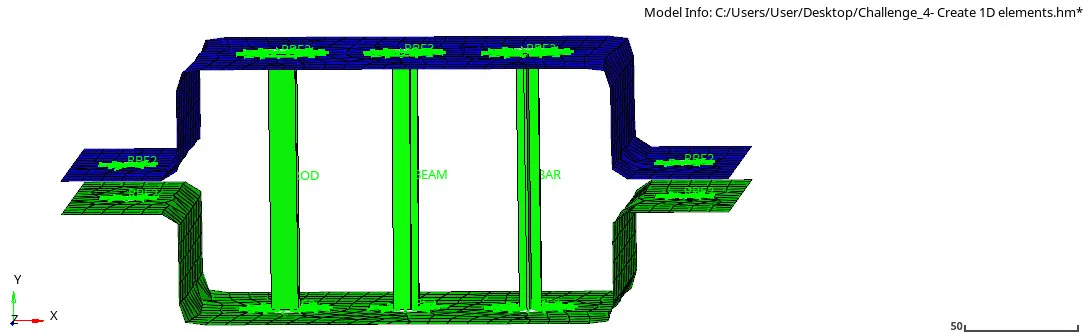
Img 10: Cross-section of 3 components (2)
- So now create a mass on (d) and (e) section with RBE2 link and with the magnitude of 10; so to create the mass follow the geometry from 1D element masses and update with particular nodes and property as "Bracket 1" and element type: "CMASS1" and update it.
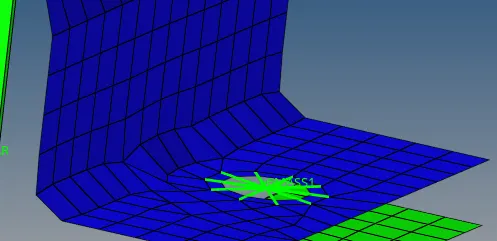
Img 11: Mass on (d) and (e)
- Join both components with a spring element, the command " springs + nodes + dof1 + property = Bracket 1 + element type = CELAS 1".
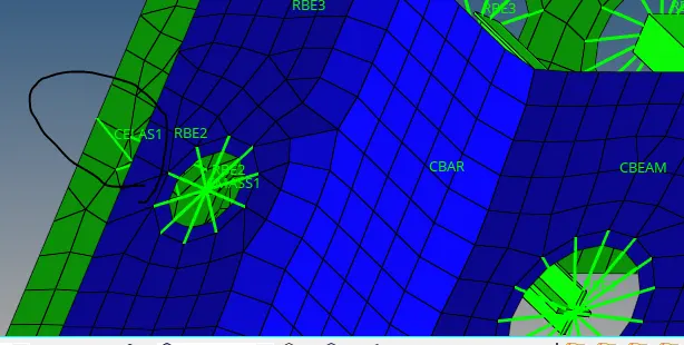
Img 12: Springs
- To get midsurface 2D into the 3D component, command "2D detailed element representation".
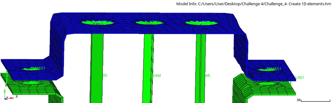
Img 13: 3D presentation of midsurface
Result and conclusion:
- Created midsurface on the given geometry to avoid storage space of node and element by meshing in 3D elements and also post-processing power.
- Created materials and their properties to each bracket and after getting materials, performed 2D mesh on the geometry to have nodes to create 1D elements
- Different types of 1D elements are created on the bracket such as ROD, BEAM, and BAR.
- Firstly, REB2 and REB3 links are created to have stiffness on each element.
- ROD, BEAM, and BAR have given dimension and cross-section using hyper beam
- All three elements are created with giving cross-section and dimension respectively and also they are assigned to their properties and components respectively.
- At last, applied mass on (d) & (e) section with a magnitude of 10 and with RBE2 link, also Joined both components with spring elements.
- The 1D elements creation concepts help us to understand how to create 1D elements such as (ROD, BEAM, BAR, MASS, and SPRINGS) on the given geometry.
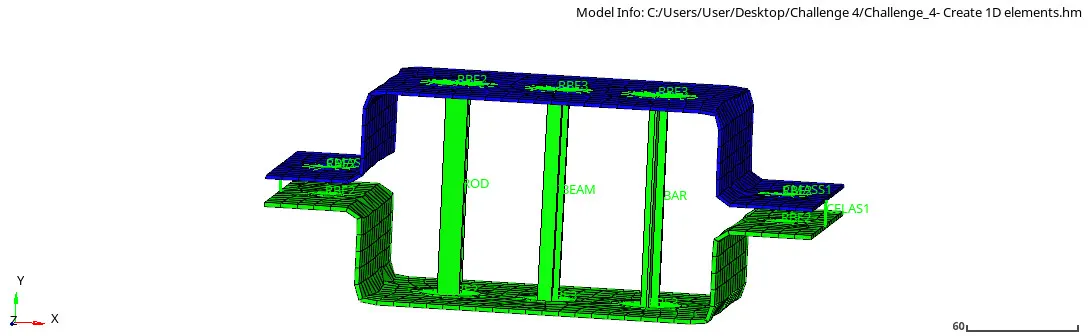
Img 14: Final 1D elements on geometry