ANSYS Week 2 Bevel Gear Challenge
WEEK 2- BEVEL GEAR CHALLENGE
AIM
To understand the concept of the grid dependency test and then run the simulation on bevel gear with 4mm, 5mm, and 6mm element size to evaluate the von-mises stress, equivalent stress, and total deformation on the bevel gear.
OBJECTIVE
Getting the overall concept of the grid dependency test and how it uses in the Ansys workbench for the simulation process, the same process needs to be applied on the bevel gear component with different element size such as 4mm, 5mm, and 6mmm but the facing of the gear should be consistent at 1.75mm.
And obtain the result for Von-misses stress, equivalent stress, and total deformation.
THEORY
Grid dependency Test- A simple concept to understand the "grid dependency test" or "mesh refinement test" in the finite element analysis that analysis begins with a coarse mesh and it is refined to a finer mesh for each run until the result does not change significantly. The finer mesh flow will have high accuracy results compare to the default mesh generated.
The main flaw of the finer mesh flow has the elements and node size will increase compared to the coarse mesh size and it will take a lot of time to evaluate the result. As this test will benefit for an accurate result because of the high-density mesh.
The main concept of this test will be to find optimum mesh size for the evaluation, where it is neither too coarse mesh nor finer mesh, as it will consume a lot of computing time to generate results.
Because of it, the grid dependency test will be evaluated on the bevel gear to obtain the optimum mesh size.
Bevel Gear- This type of gear where axes of two shaft intersect and the tooth-bearing faces of the gear themselves are conically shaped. The bevel gear is mostly mounted where the shafts that are 90 degrees to each other but they can be worked at other angles as well. The pitch surface of bevel gear is cone
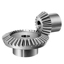
Fig 1: bevel gear
PROCEDURE
SETUP
Using the static structural material for the bevel gear as the properties of static structural is mentioned below:
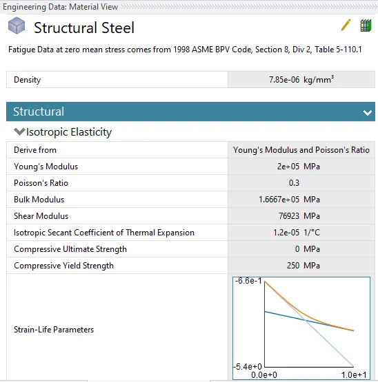
Fig 2: Properties of static structural
The geometry is imported in SpaceClaim and edited with the unwanted extra surface that needs to be cut down for the big gear with 45mm and to the small gear with 25mm, which unnecessary part and not required for the simulation process.
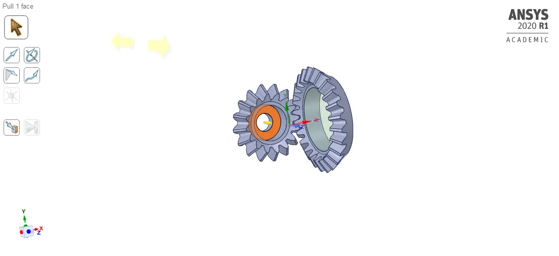
Fig 3: Removing unnecessary surface
The geometry is opened in the mechanical module for the simulation process whereas renaming the gears with big gear/solid and small gear/solid. The material for the bevel gear is given as standard as static structural and the coordinate system as a global coordinate system.
On the connection based the contacts to be named on the (Renamed Based on definition) - frictional small gear - to big gear.
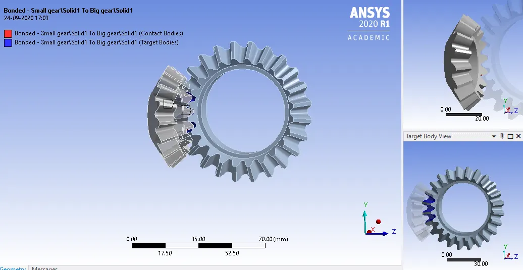
Fig 4: Renamed based on the definition
Contacts
Selecting the faces for contact body - 16 Faces and target body 24 faces.
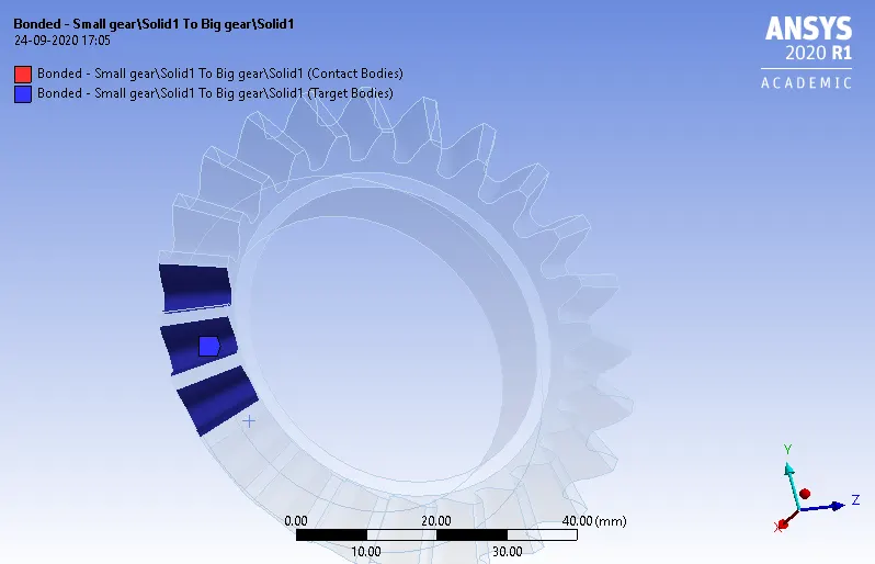
Fig 5: Target face
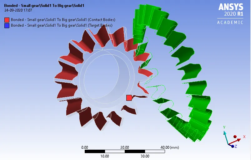
Fig 6: Contact face
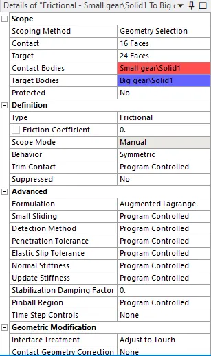
Fig 7: Contact and target setup
Joints
Two revolute joints are provided for the big gear and small gear as connection type (Body-Ground) and type- revolute.
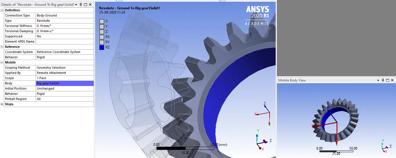
Fig 8: Revolute joint big gear
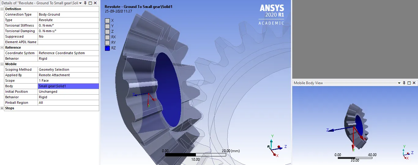
Fig 9: Revolute joint small gear
Mesh
As this project is focused on the grid dependency test which evaluates the mesh that changes the resulting output in the bevel gear simulation first the geometry is mesh which 6mm in size.
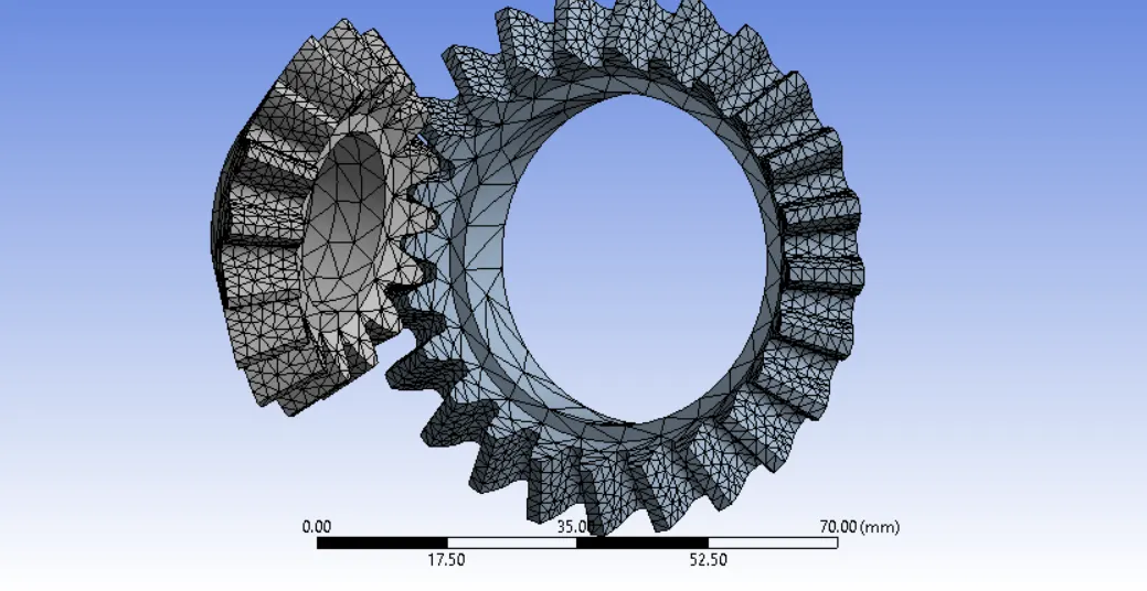
Fig 10: 6mm mesh

Fig 11: 6mm mesh statistics
For all the other three mesh sizes and for their solution to obtain the accurate results, the face sizing both gear faces are selected with and mesh with 1.75mm size.
Analysis settings
For setting up the simulation for taking out the result the 6 steps are taken with an auto time step on, defined by time and Initial time step 0.1s, minimum time step 0.005s maximum time step 0.5s.
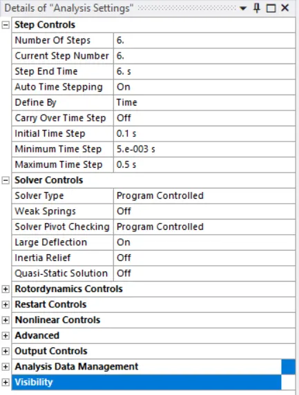
Fig 12: Analysis settings
Joint Moment
To rotate the big to the opposite side of the small gear joint is given to it with selecting the inner surface of big gear with the type of moment and magnitude as tabular data with 100 Nmm of force at each step.
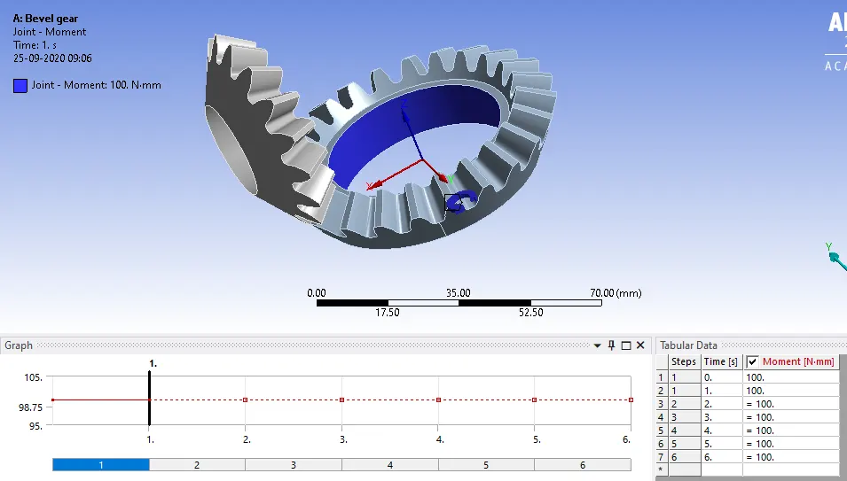
Fig 13: Joint load moment
Joint Rotation
To rotate the small gear joint rotation is given with selecting inner surface and type of rotation with the angle of 20 degrees at each step.
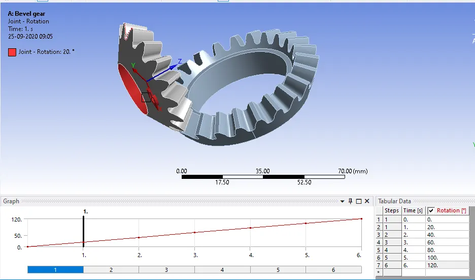
Fig 14: Joint load rotation
As the small gear is rotating about the same axis rotation so to rotate the opposite side, the coordinate system has been changed to change the angle of rotation to the RZ axis.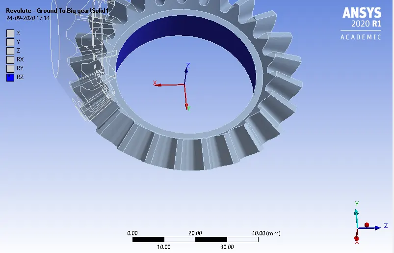
Fig 15: Changing the coordinate system
For evaluating the result for the grid dependency test for 6mm, 5mm, and 4mm mesh size the output is obtained for Equivalent Nonvises stress, Equivalent elastic strain, and Total deformation.
RESULT
Case 1: For 6mm size and face sizing 1.75mm size
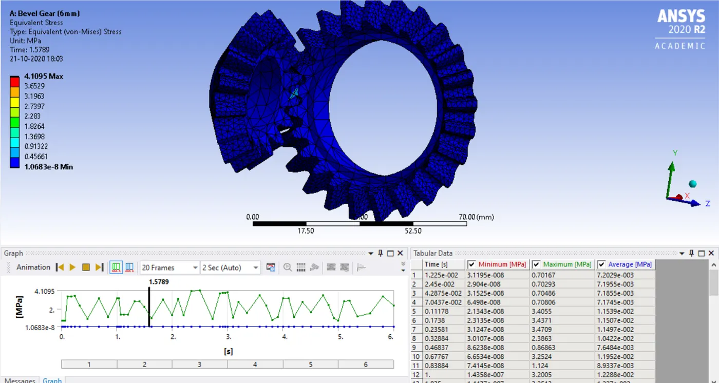
Fig 16: Equivalent stress
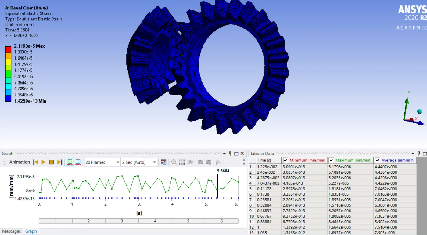
Fig 17: Equivalent strain
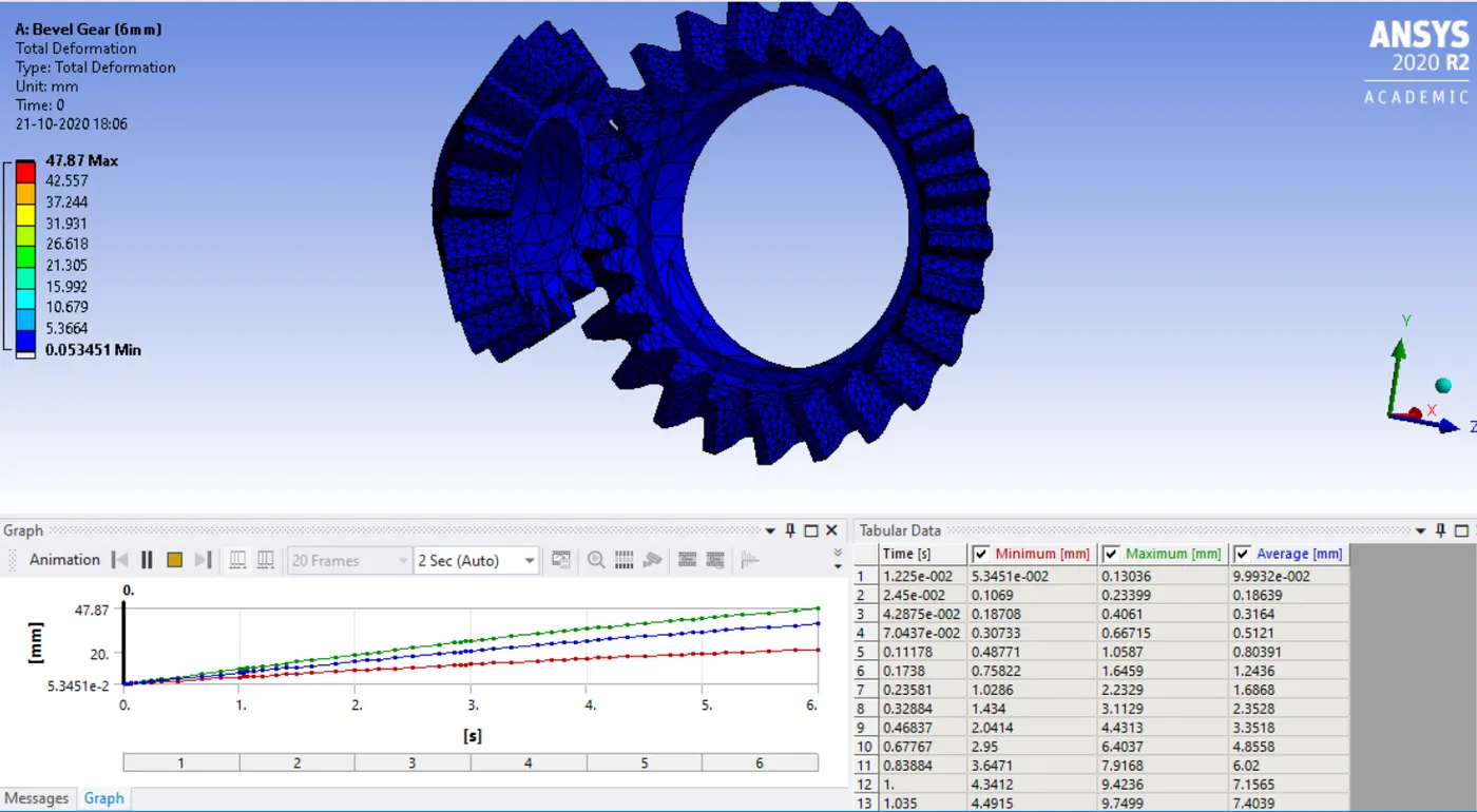
Fig 18: Total deformation
Case 2: For 5mm size and face sizing 1.75mm size
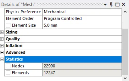
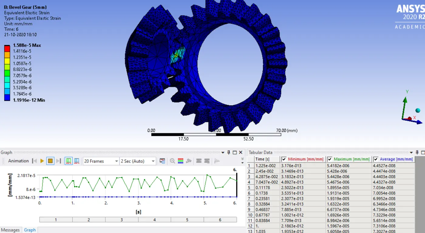
Fig 19: Equivalent stress
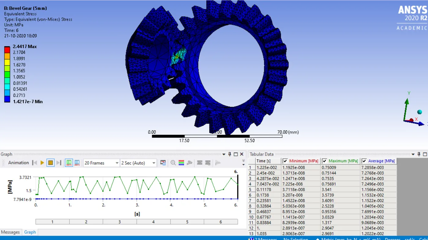
Fig 20: Equivalent strain
https://youtu.be/aBEOxJdDwjk
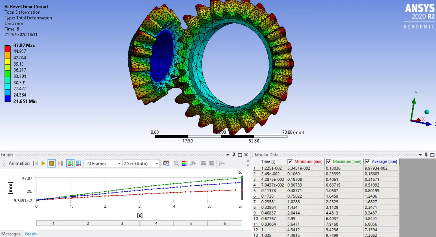
Fig 21: Total deformation
Case 3: For 4mm size and face sizing 1.75mm size
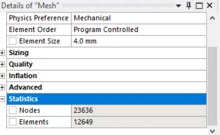
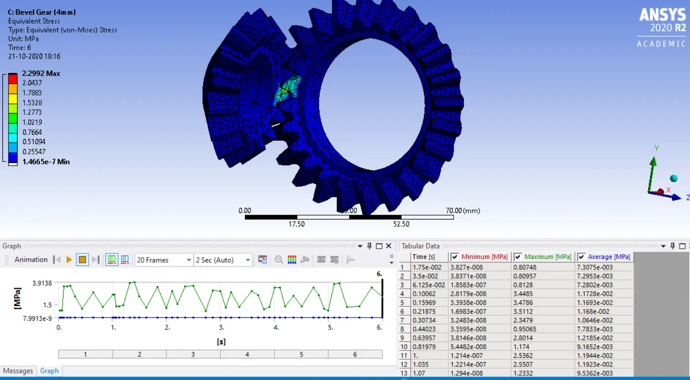
Fig 22: Equivalent stress
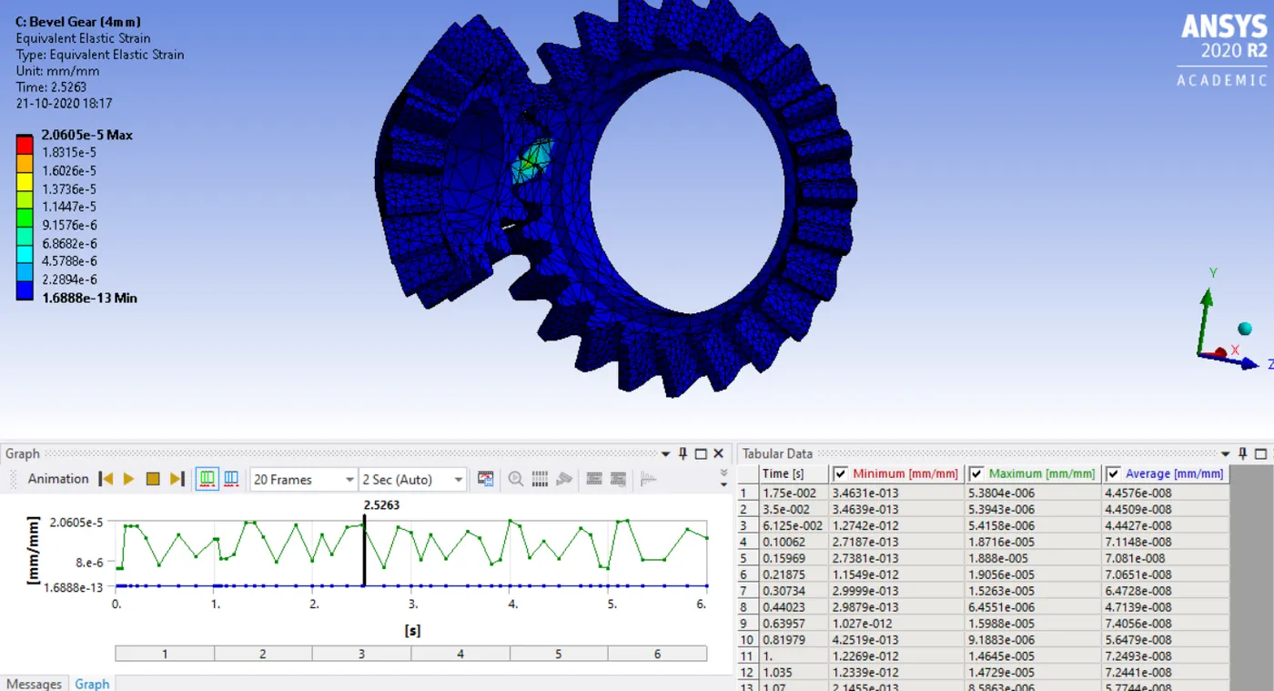
Fig 23: Equivalent strain
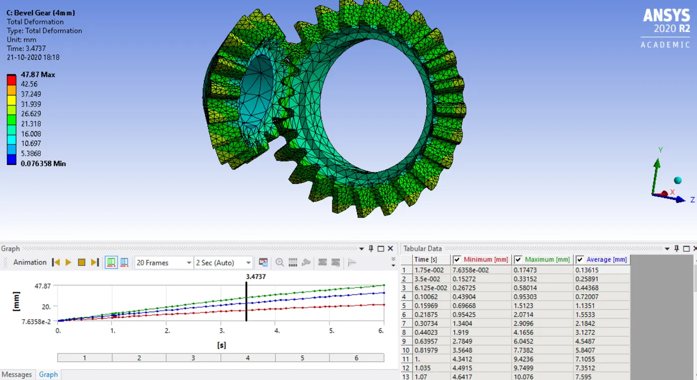
Fig 24: Total deformation
Result Comparison
| Mesh Size | Equivalent Stress minimum (MPa) | Equivalent Stress maximum (MPa) | Equivalent Strain minimum (mm/mm) | Equivalent Strain minimum (mm/mm) | Total deformation minimum (mm) | Total deformation minimum (mm) |
| 6mm | 1.5095e-007 | 2.4016 | 1.0875e-012 | 1.5709e-005 | 21.651 | 47.87 |
| 5mm | 1.4217e-007 | 2.4417 | 1.1916e-012 | 1.588e-005 | 21.651 | 47.87 |
| 4mm | 1.4665e-007 | 2.2992 | 1.0162e-012 | 1.5087e-005 | 21.651 | 47.87 |
As we see along the equivalent non-vises stress evaluates the result that the increase in the number of numbers means fine mesh gives more accurate result compared to large element size as we look the table and result of simulation 6mm size equivalent stress for 1.5095e-007 (min) to 2.4016 (max), 5mm size 1.4217e-007 (min) to 2.4417 (max) and for 4mm size 1.4665e-007 (max) to 2.2992 (max).
The result for equivalent strain evaluates that for 6mm size minimum strain is 1.0875e-012 to 1.5709e-005 (max) for 5mm size 1.4217e-007 (max) to 2.4417 (min) and for 4mm size 1.4665e-007 (min) to 2.2992 (max), the finer mesh gives much accurate result to obtain the starin value.
But comparing those results to the total deformation grid dependency test doesn't seem to many changes as it is equal to all three mesh sizes with similar results for 6mm, 5mm, and 4mm size is 21.651 (min) to 47.87(max).