Hypermesh Challenge_3 (Creating simple Bracket, Extract CAD surface from FE and Mesh on Given model)
PART 1 - Creating a model as per given dimension
Objective: To create a simple bracket in the Hypersmesh using Geometry tool on the given dimension.
Procedure:
- First Phase of Bracket:
- To create four nodes at an equal distance of 100mm [Command: Geometry + Nodes]
- Then nodes should be connected with lines at the same distance of 100mm [Command: Geometry + lines + linear node]
- To create the first phase of the bracket, create a surface on the nodes [Command: Geometry + Surface + Ruled]
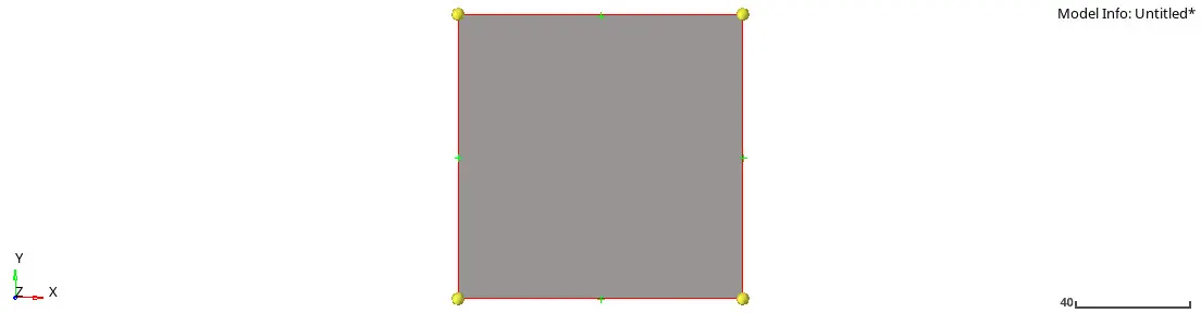
Img 1: First Phase of Bracket
- Second Phase of Bracket:
- Creating the second phase of the bracket, extract the node at z-direction by duplicating the nodes [Command: Tool + Translate + select nodes+ Duplicate + vector direction + magnitude at 100mm]
- After getting the node at the perpendicular direction to the bracket, they should be connected with lines to have the base surface [Command: Geometry + lines + linear node]
- For surface again same action [Command: Geometry + Surface + Ruled]
Img 2: Second Phase of Bracket
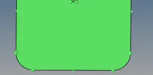
- Cutting down the edges at the dimension of Radius (R-15) [Command: Geometry + line + conic]
- Trim the edges with surface edit, trim with lines, select the surface and select the line and it should be normal to the surface then trim the section
- Trim section should be deleted by giving the command to delete option, select the trim surface, and delete the entity.
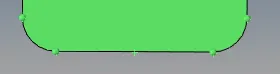
Img 3: Edges fillet on the second phase of Bracket
- To create a Rib between both phase of the bracket, get a node in between of both phase of bracket then mid nodes on both surfaces, a command to the ribs section, selecting the rib type: triangular, then selecting a start and end node of ribs, giving a vector direction and dimension to the ribs H= 40mm and Length= 5mm.
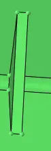
Img 4: Rib of Bracket
- For Surface fillet on the bracket [Command: Surfaces + Fillet ] Now selecting the lines and Radius of 5mm and create the surface fillet.
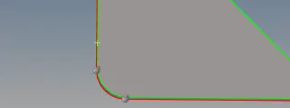
Img 5: Surface fillet
- Create a hole on the upper bracket of Radius 5mm, to enhance the hole get few nodes on the upper line of the first phase of the bracket at a distance of 25mm each and nodes also on sidelines with the same distance 25mm, get the center of the hole at the height of 25mm and length of 50 mm
- Then create a circle of R=5mm and trim it with the surface, after getting circle surface trim, [Command delete + select the trim surface and delete the entity]/
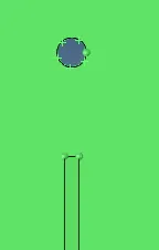
Img 6: Hole
- To cut the side edges at the first phase of the bracket, select the same nodes taken for hole measurement assuming distance, a node from the upper line 25mm and sideline of the bracket of both side 25mm, then create a line to have an edge on the bracket, getting this line trim from surface edit and delete the trim surface with delete tool.
- We will have the edge on the upper surface of the bracket.
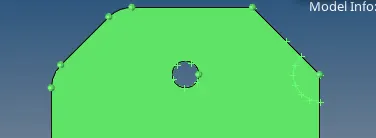
Img 7: Side fillet edges of Bracket
- To select the arc on the left side of the upper phase of the bracket [ Command: Lines + Arc center and nodes + radius = 10mm + Angle = 270 degree]
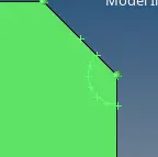
Img 8: Arc
- For fillet edges on the right side of the upper phase of the bracket, get a node on upper line at 10mm each sideline at 10mm each and bottom line 10mm each on the upper phase of the bracket then taking [Command: line + Conic + (Start point + End point+ Tangent point) + create)
- Trim that surface with surface trim and then delete the trim surface with delete entity to have fillet edges.
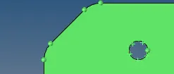
Img 9: Edges fillet
Conclusion
The bracket has been created using the geometry cleanup using different types of tools, below I have shown the created bracket images.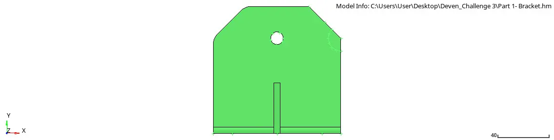
Img 10: Front View of Bracket
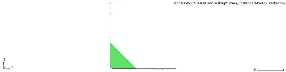
Img 11: Side view of Bracket
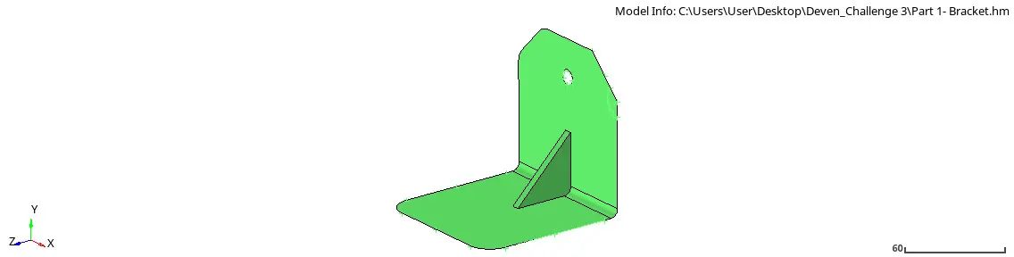
Img 12: Isometric View of Bracket
The concept to create the bracket using geometry in the hypermesh to get them familiar with the tools given in the geometry cleanup so that if we import any model from the CAD team while importing the geometry will have to get messed up, so to enhance the proper geometry on the model tools should be familiarised.
---------------------------------------------------------------------------------------------------------
PART 2 - Extracting CAD from the FE
Objective: To extract the CAD model surface from the finite Element Analysis.
Procedures:
- Import the CAD model from the file.
- Check the dimension of the model and start for the process of surface extract from the finite element model.
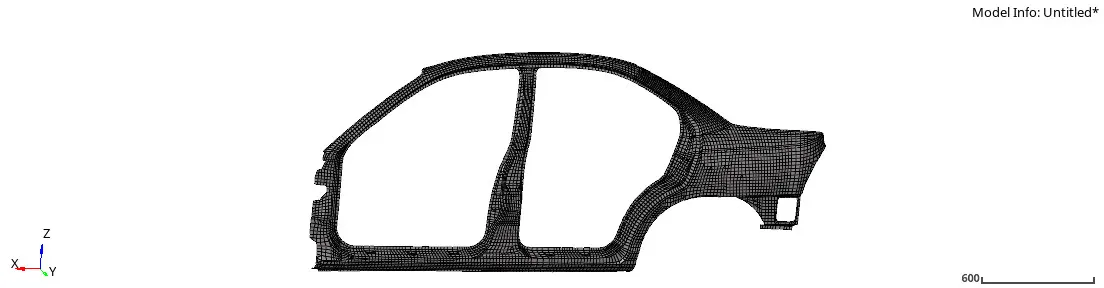
Img 13: CAD before the surface extract
- To extract the surface follow a certain step by giving an appropriate command in the geometry cleanup.
- Command surface tool and select From the FE tool, then select all elements with (Auto Detect features, Mesh-based auto too ) and then create.
- We will have the surface from the finite element model.
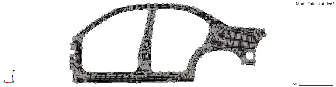
Img 14: Surface Extract from FE
Conclusion: The process was to get acknowledge how to extract the surface for further geometry cleanup and edit from the given FE model.
---------------------------------------------------------------------------------------------------------
PART 3- Generating mesh on the given component
Objective: To generate the 2D mesh on the given model.
Procedures:
- Import the geometry from the files.
- Check the geometry and go for autocleanup then select the geometry and check the parameter as (use current parameter) and do autocleanup
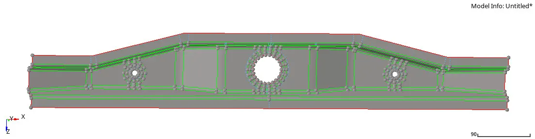
Img 15: Surface Extract from FE
- After autocleanup reject it and go to 2D in automesh select the surface, give the element size 10 and mesh type (mixed), and finally do the mesh.
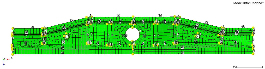
Img 16: mesh 1
- After checking the mesh see the surface and check the geometry and reject it. Go to the quick edit "Washer split" select line and offset value of 5 . select the hole and offset to get the correct element on the surface
- Again do the mesh with the same no of element and procedure. After 2nd meshing, increase the node and make them at same no of a hole to have the proper geometry
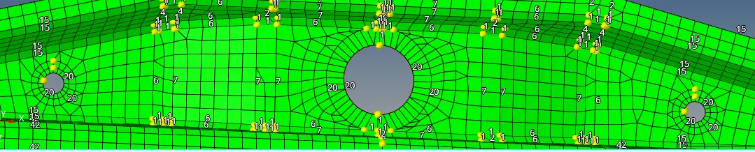
Img 17: Washer split, mesh, and node symmetric
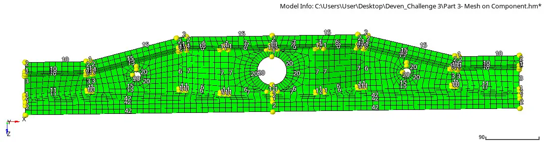
Img 18: final mesh
Conclusion: To get the idea of how to do mesh on the given geometry and check them with proper elements on the surface after meshing.
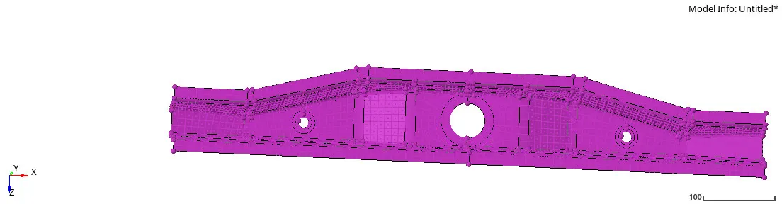
Img 19: Mesh on the given geometry
--------------------------------------------------------------------------------------------------------------------