Week 11 Car Crash simulation
Ansys Week 11: Car Crash Simulation
AIM
To perform the parametric study for 3 different values of thickness for the car body.
OBJECTIVE
The video is provided for the car crash simulation for boundary condition and simulation setup, need to perform the parametric study using three different values of thickness for the car body in the explicit Analysis.
THEORY
Parametric study
The impacts that changing certain parameters can have on the design. The parameters can include dimensional parameters. Parametric studies allow you to nominate parameters for evaluation, define the parameter range, specify the design constraints, and analyze the results of each parameter variation.
A parametric study requires the following:
- Design Objective is set to Parametric Dimensions.
- Parameters nominated for use in the simulation.
- Parameter ranges identified.
- Design criteria specified.
- Various configurations generated.
Explicit Analysis
The explicit analysis offers a faster solution in events where there is a dynamic equilibrium or otherwise:
Sum of all forces = mass * acceleration
The explicit should be used when the strain rates/velocity is over 10 units/second or 10m/s respectively. These events can be the best exampled by extreme scenarios such as automotive crash, ballistic event,s or event meteor impact.
Implicit Analysis
The implicit methods should be used when the events are much slower and the effects of strain rates are minimal. Once the growth of stress function of strain can be established, these can be analyzed using implicit methods. In this case, can be analyzed using implicit methods. In this case, one can consider a static equilibrium such that:
Sum of all forces = 0.
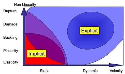
Fig 1: Non- Linearity of explicit-and-implicit-analysis
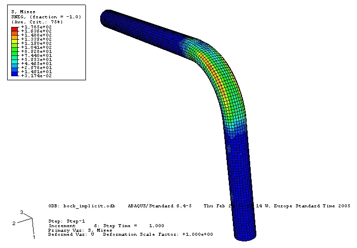
Fig 2: Implicit-analysis
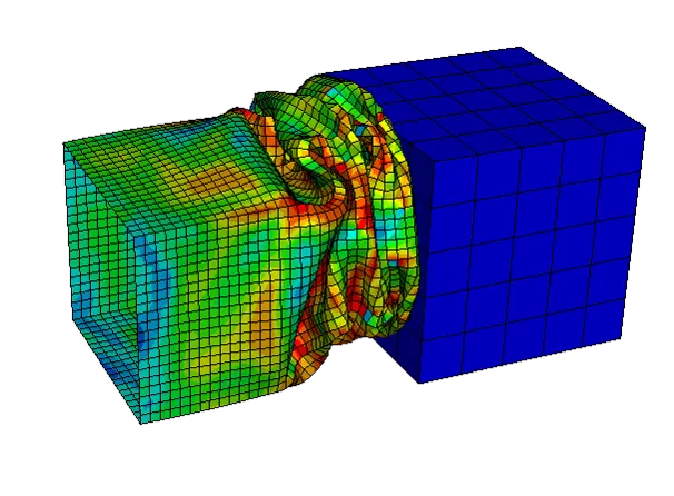
Fig 3: Explicit Analysis
PROCEDURE
Setups - Geometry
Importing the geometry into the SpaceClaim to check the car and wall geometry surface and their any irregularities between surfaces that need to be fixed but the geometry is fine to set up the boundary conditions.
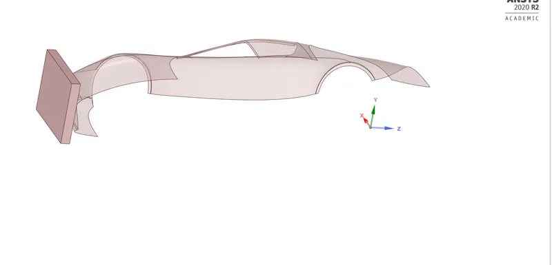
Fig 4: Geometry
Rename each part of the body as a there Car body, Wall, and other two parts that are not visible that need to be suppressed, For the wall using structural steel as the material and for the car body stainless steel with a thickness of 0.4 0.3 and 0.2 setting up the parameters for different values.
Symmetry
Adding up the two symmetry region to the geometry symmetry region 1 for that car body part by selecting the edge interface and adding 12 edges of the car body.
Second symmetry region one side of face o the wall.
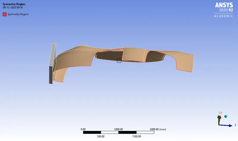
Fig 5: Symmetry region of Car body
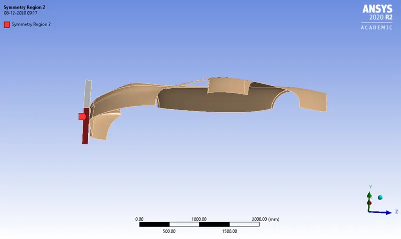
Fig 6: Symmetry region 2
Contact Region
The body is going to be in contact with the wall so adding up the contact region with the contact body as the wall and the target body to be the car body.
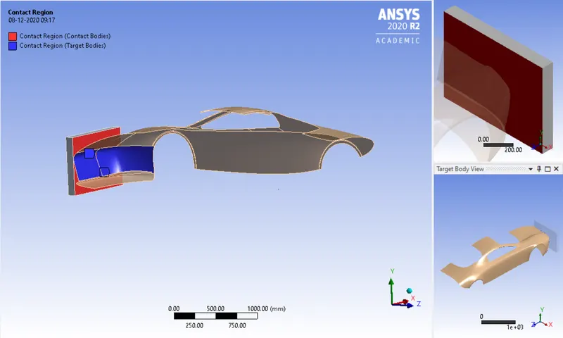
Fig 7: Contact Region
Mesh
Using patch conforming method for the wall, as selecting whole body size and with the elements as tetrahedrons. But for the car body selecting the filter as the face sizing with the size of the element as 175mm to the selected 6 faces of the car body.
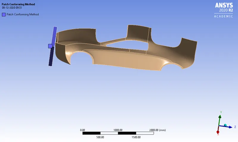
Fig 8: Patch conforming method
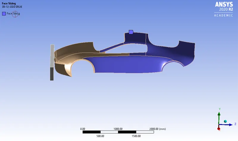
Fig 9: Face sizing
Default mesh is generated with a total no of nodes are 25911 and elements as 27987 which is below the academic limit.
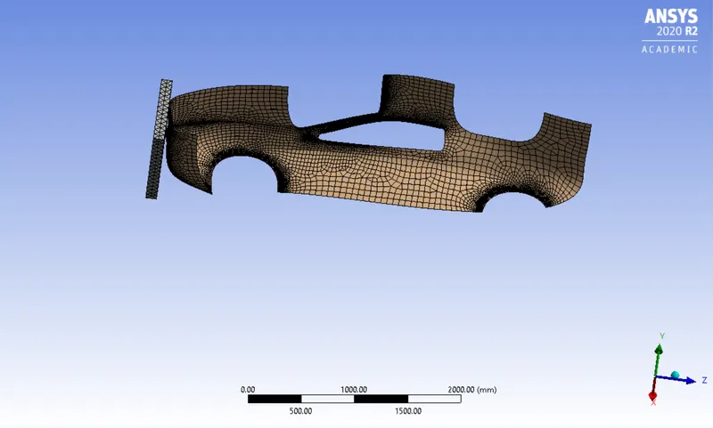
Fig 10: Mesh
Analysis settings
Setting up the analysis for the simulation purpose giving value to the end time (1 e-003) and other settings to be same.
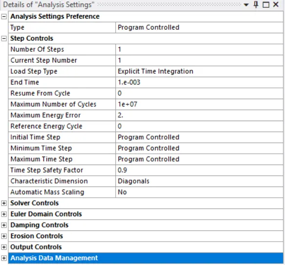
Fig 11: Details of analysis settings
Adding fixed support to the body by selecting the 6 faces of the body which will not in contact with the wall body while crashing between them.
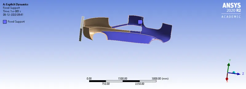
Fig 12: Fixed support
Selecting the side face of the wall by giving the displacement 500 mm to the z-axis and time as the (1 e-003).
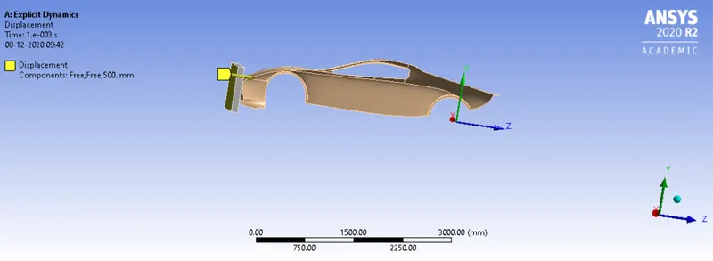
Fig 13: Displacement
RESULTS
Case 1: Parametric Value of 0.4mm
Total deformation
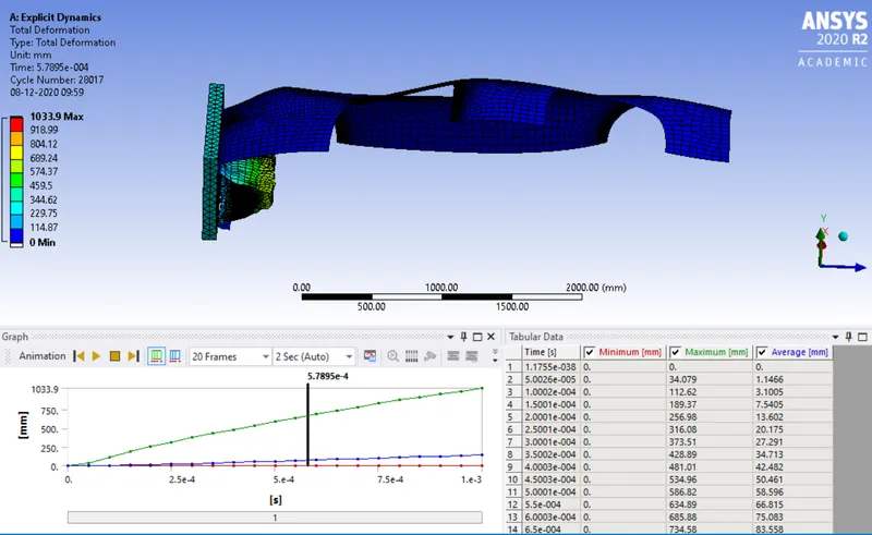
Fig 14: Total deformation
Equivalent von mises stress
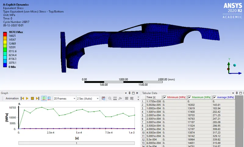
Fig 15: Equivalent stress
Parameters set as a parametric study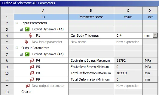
Fig 17: Parameters
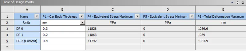
Fig 18: Table design points
Parametric study result for equivalent stress value and total deformation
| Sr. No | 0.4 mm | 0.3 mm | 0.2 mm |
|
Minimum Equivalent stress (MPa) |
0 | 0 | 0 |
|
Maximum Equivalent stress (MPa) |
11792 | 11826 | 11863 |
|
Minimum Total deformation mm |
0 | 0 | 0 |
|
Maximum Total deformation mm |
1033.9 | 1036.6 | 1039 |
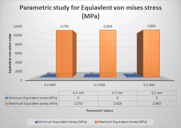
Fig 19: Graph for equivalent von mises stress
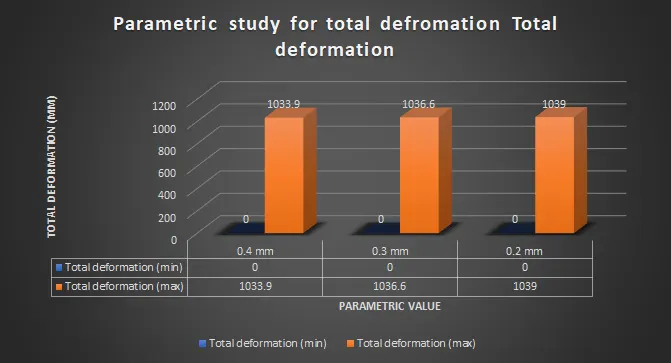
Fig 20: Graph for total deformation
CONCLUSION
The simulation is run successfully in the Ansys workbench using explicit dynamics for the Car crash simulation, to study different parametric values such as 0.2, 0.3, and 0.4. In this case study, the simulation values show the thickness of the body increases the equivalent von Mises stress gets decreased and the total deformation value also get increases.
--------------------------------------------------------------------------------------------------------------------------------------------------------------------------------------------------------------------------------------------
Files: https://drive.google.com/drive/folders/1COi3sNRyi9cRODSs-Z0US3aq59gB4wc6?usp=sharing