Week 5 Bending of iPhone
Ansys Week 5: Bending of iPhone
AIM
To simulate the bending of iPhone in structural analysis with two different cases.
OBJECTIVE
This challenge is to simulate the bending of the iPhone using Ansys workbench with two different cases.
Case 1: The setup and geometry would be at the same position mentioned in the video.
Case 2: Move the fingers from their defined position to the given position x = 22.5mm & z = 10mm and obtain the result for the simulation. Also, define the S-N curve for the aluminum alloy material as per given values.
| Stress, MPa | Number of Cycles, N |
| 225 | 10000 |
| 175 | 100000 |
| 143 | 1000000 |
| 110 | 10000000 |
| 80 | 100000000 |
MATERIAL PROPERTIES
Aluminium Alloy
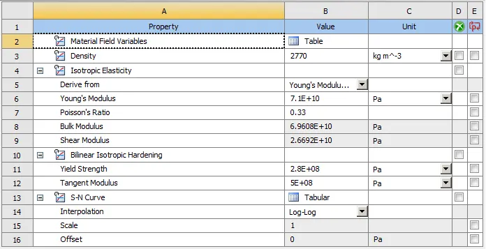
Fig 1: Properties of Aluminum Alloy
Glass
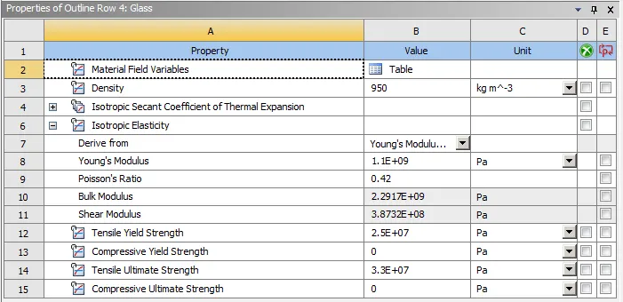
Fig 2: Properties of Glass
Polyethelene
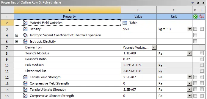
Fig 3: Properties of Polyethelene
Structural Steel
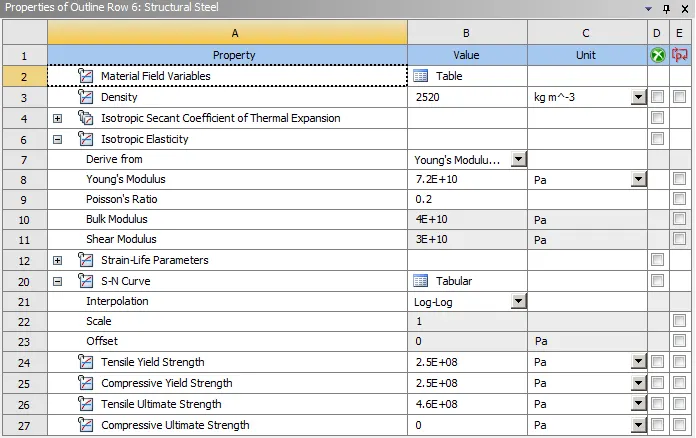
Fig 4: Properties of Structural Steel
S-N Curve
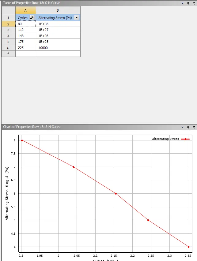
Fig 5: S-N curve for Aluminum Alloy
PROCEDURE
Setup
Importing the geometry in the space claim to check each part of the iPhone geometry and to check the surface damages for Case 1 and for Case 2 changing the position of the pushing fingers towards x = 22.5mm & z = 10mm.
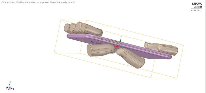
Fig 6: iPhone bending Geometry Case 1
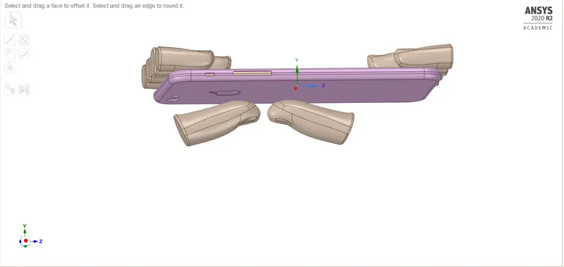
Fig 7: iPhone bending Case 2 Geometry
Rename each of the geometry as a frame, Display, Insides, Pushing fingers 1 and 2 and other all top faces as fingers also assigning the materials to the frames as Aluminium alloy, Display as Glass, Insides as the Polyethelene, and the fingers as the structural steel.
For the fingers and the pushing fingers, the stiffness behavior as Rigid.
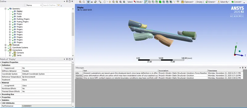
Fig 8: Rename the geometry
Connections
Contacts
Two contacts between the fingers are unknown, so this connection is deleted and the other connection Rename based on the definition and the define the contacts for a display to frame as the type to be bonder and other all contacts to be frictionless.
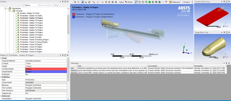
Fig 9: Contacts
Joints
The body to ground fixed type joint is given between the fingers and the translation joints to the pushing fingers from the body to the ground.
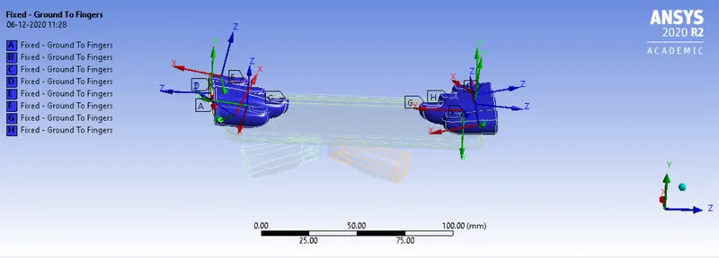
Fig 10: Fixed Joints
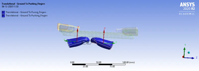
Fig 11: Translation Joints
Mesh
Selecting the faces of the pushing fingers as the 7 faces with default size and the mesh is generated with nodes obtain as 19462.
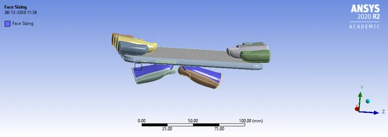
Fig 12: Face sizing
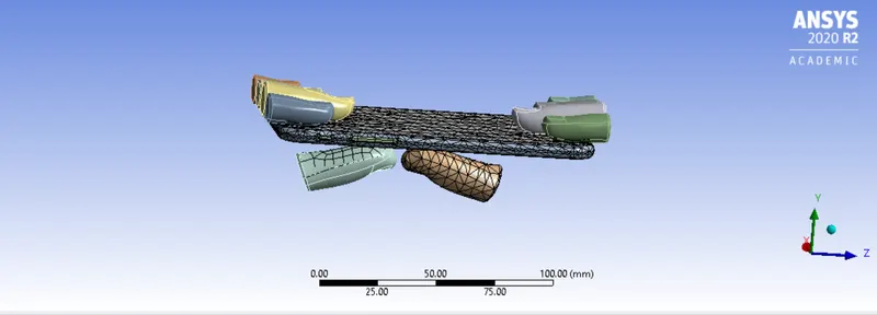
Fig 13: Mesh
Analysis settings
The 8 septs are given to the simulation of the iPhone bending, for the solver type as direct and the large deflection is ON, with the stabilization is constant and the energy dissipation as 0.1. All the output controls to be ON.
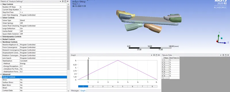
Fig 14: Analysis settings
The fixed support is given to the insides and the 4 faces of the frame with x and z constant and y-direction to be free in nature.
Fig 15: Fixed Joints
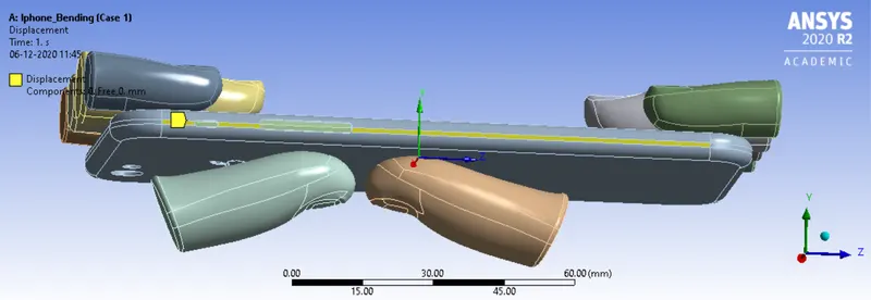
Fig 16: displacement
Two displacements are provided for the pushing fingers at the distance of (0, 2, 4, 6, 8, 4, 6, 4, 2, 0) for each step to be followed.
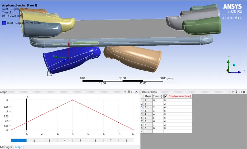
Fig 17: Joint displacement 1
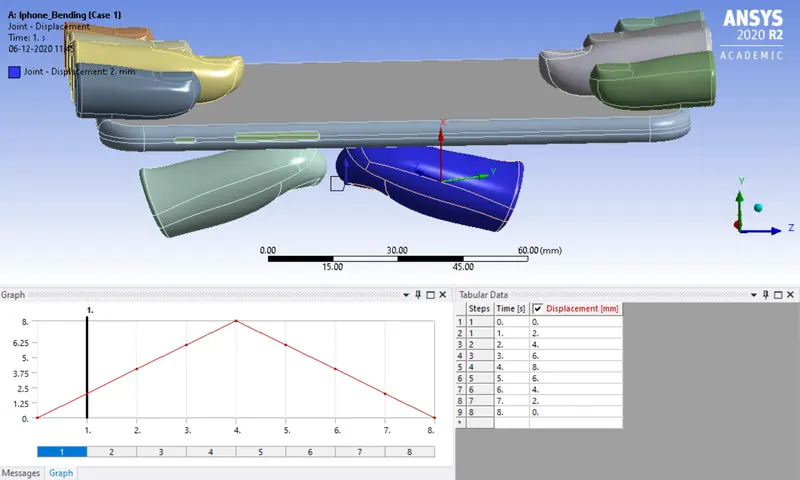
Fig 18: Joint displacement 2
RESULTS
Case 1: Boundaries condition as per the video
Directional Deformation
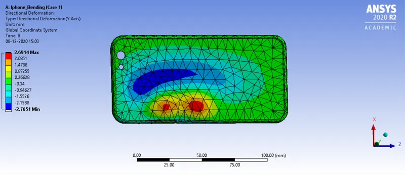
Fig 19: Directional deformation
Equivalent von mises stress
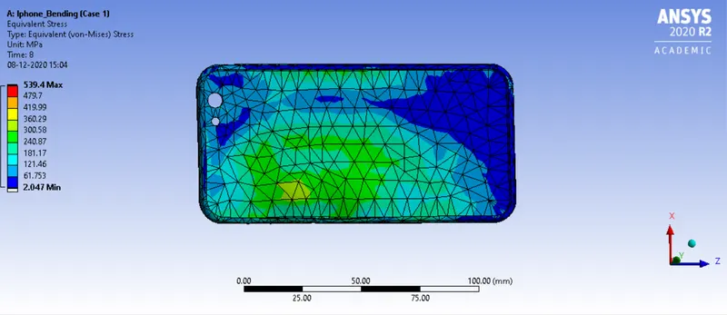
Fig 20 Equivalent stress
Equivalent elastic strain
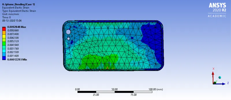
Fig 21: Equivalent elastic strain
Case 2: Boundaries condition as per S_N curve and geometry change
Directional deformation
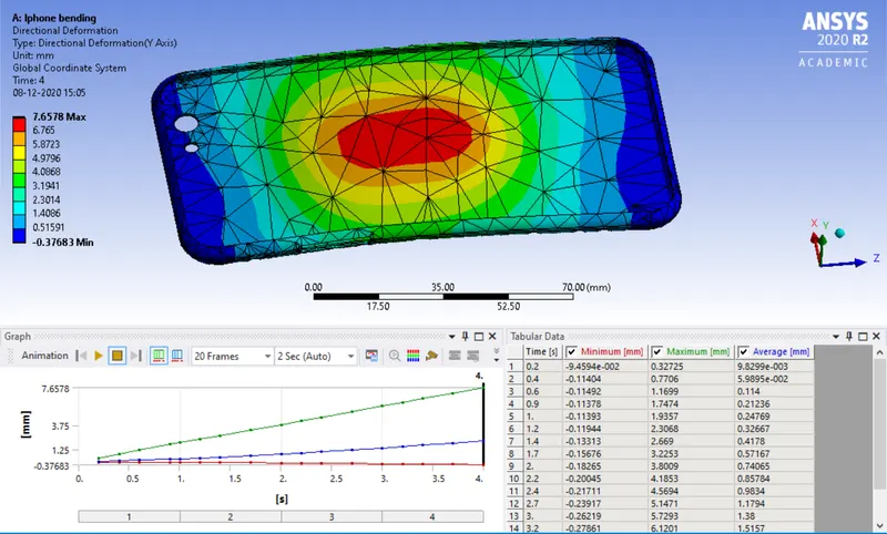
Fig 25: Directional deformation
Equivalent von mises stress
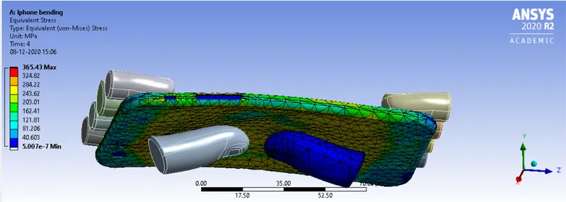
Fig 26: Equivalent stress
Fatigue Life
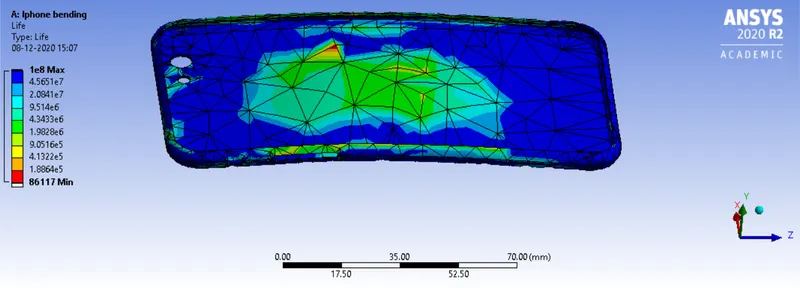
Fig 27: Fatigue life
CONCLUSION
The setup and boundary conditions for both the cases are run successfully and obtained all the results for fatigue life, direction deformation,and the equivalent von mises stress.
--------------------------------------------------------------------------------------------------------------------------------------------------------------------------------------------------------------------------------------------