Week 4- Rolling operation
ANSYS WEEK 4 - ROLLING OPERATION
AIM:
To simulate the rolling operation on a workpiece made of copper and evaluate the result with different parameters.
OBJECTIVE:
The main purpose of this challenge is to simulate the rolling bar operation on a workpiece made of copper, making some geometry changes and then running the simulation for 14 steps by giving random values for the displacement but the workpiece should be displaced up to 90mm.
THEORY:
Rolling is a deformation process of a metal that is widely used in the metal forming process. It is done by passing the strip of the metal between the rollers. This paper discussion will be made about the rolling process, the working principle of the rolling process along with that the working principle of the rolling mills.
Working Process: The rolling process is a metal forming process, in which stock of the material is passed between one or more pairs of rollers to reduce and to maintain the uniform thickness. This process is mainly focused on the cross-section of the ingot or the metal which is forming. Mainly by this process, we reduce the thickness of the metal workpiece.
Now, the rolling process is mainly focused on the increasing length and the decreasing thickness without changing the width of the workpiece. There are certain, types of rolling processes, whereas, in the hot rolling process the metal is heated at its desired temperature when the metal is properly heated then the metal should be passed between one or more rolling mills to gain the proper desirable shape.
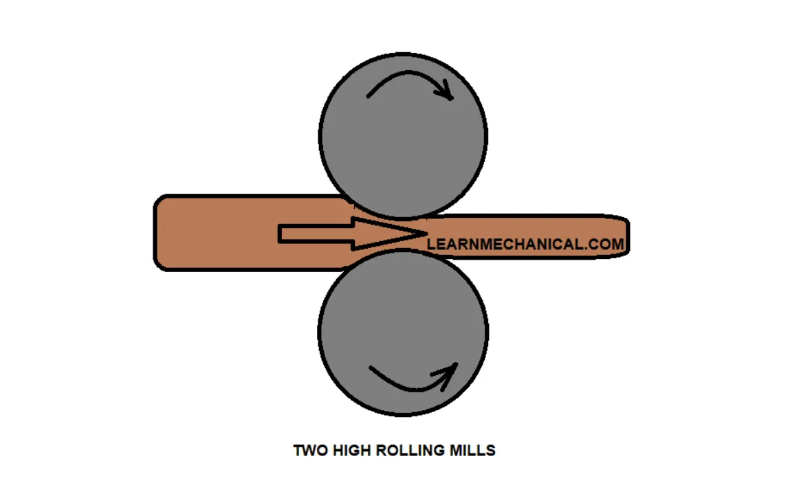
Fig 1: Two rolling mills
PROPERTIES
Structural Steel
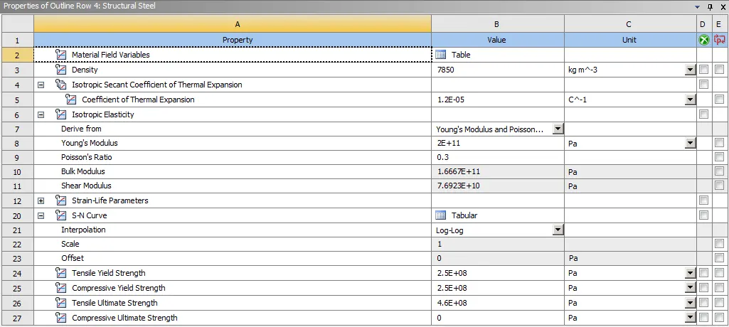
Fig 2: Properties of structural steel
Copper Alloy
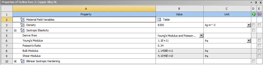
Fig 3: Properties of copper alloy
PROCEDURE
SETUP
Giving the properties as structural steel and copper alloy to the setup and then opening the geometry in the SpaceClaim module to change some parameters like the height of the piece increased by the 60mm and its size from the side decrease by the 8mm.
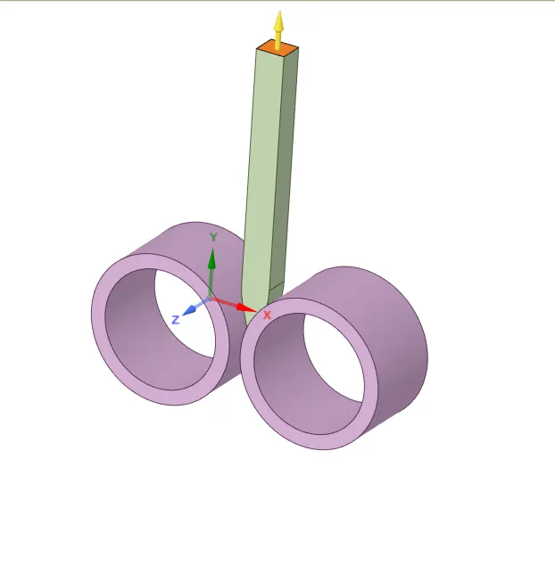
Fig 4: Rolling operation geometry
Then, the geometry is opened in the mechanical module for the simulation setup. Renaming each part of the geometry wheel 1, wheel 2, and workpiece.
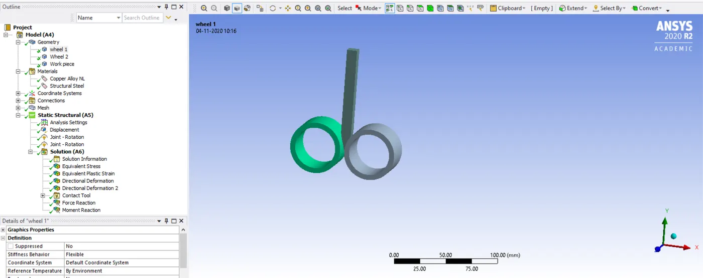
Fig 5: Rename components
Contacts
Two frictional contacts are given to the setup first contact to the outer side of the wheel and right sid of price whereas the second contact is given to the wheel two and left side of the piece. Frictional type is given with friction coefficient 0.2, Behaviour as Auto Asymmetric, Formulation is by augmented Lagrange, Normal stiffness is a factor with stiffness factor 0.1, update stiffness is each iteration, Interface treatment is Add offset, Ramped effects.
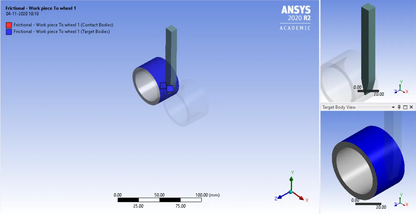
Fig 6: Contact 1 Workpiece to wheel 1
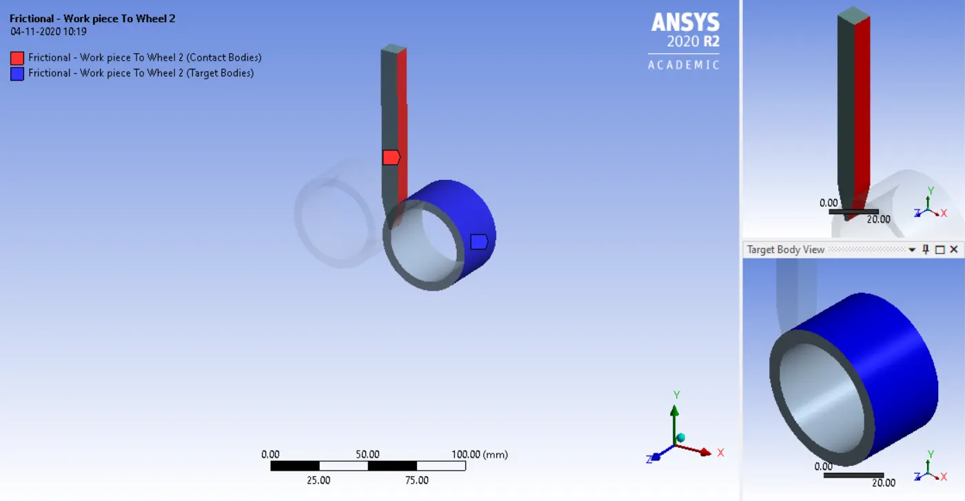
Fig 7: Contact 2 Workpiece to wheel 2
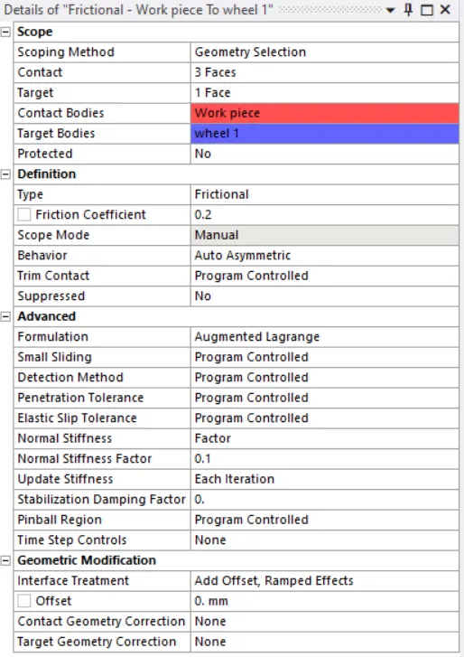
Fig 8: Details of frictional
Joints
The connection type is a body to the ground, selecting the scope of 1 and body wheel 1 and the same of the joint of wheel 2.
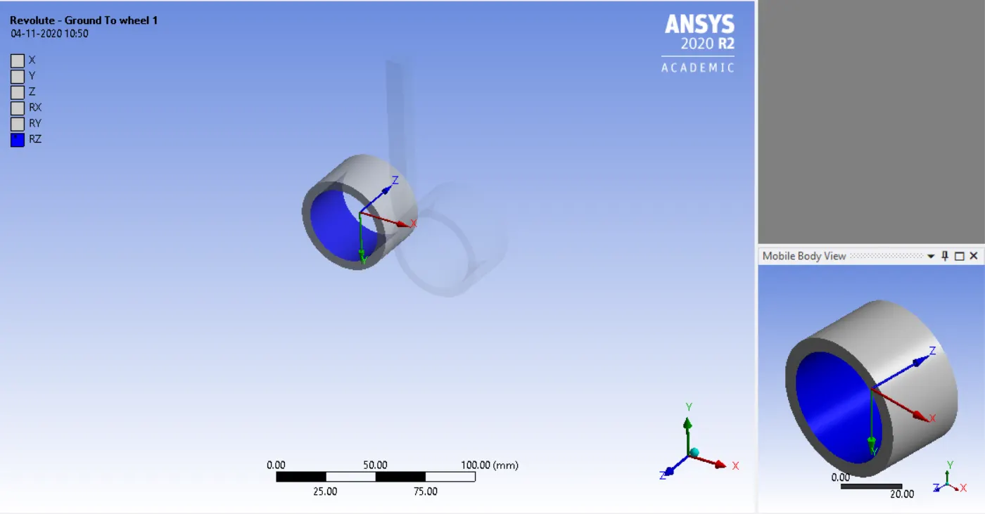
Fig 8: Revolute - ground to wheel 1
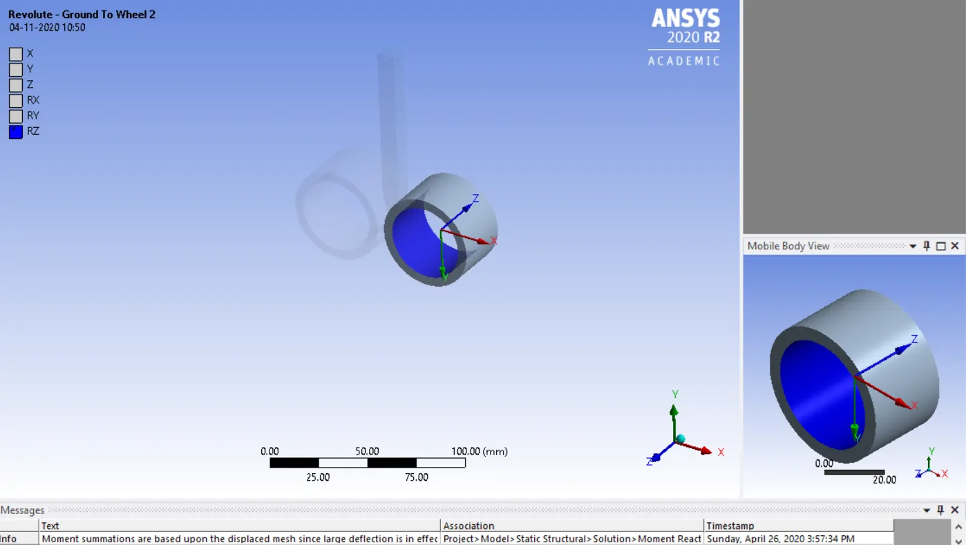
Fig 9: Revolute - Ground to wheel 2
Mesh
The mesh for the piece is given by the body sizing with the element size 4mm. and the default meshes for the other part of the geometry.
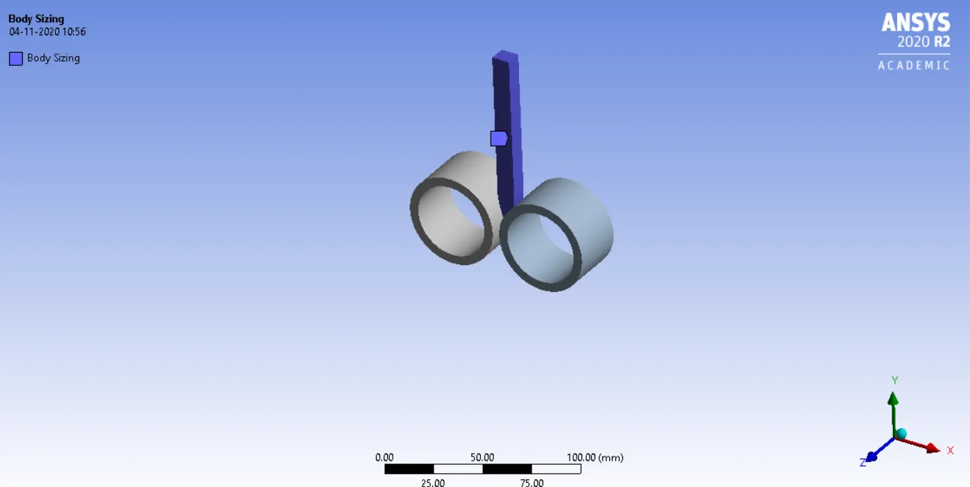
Fig 10: Body sizing
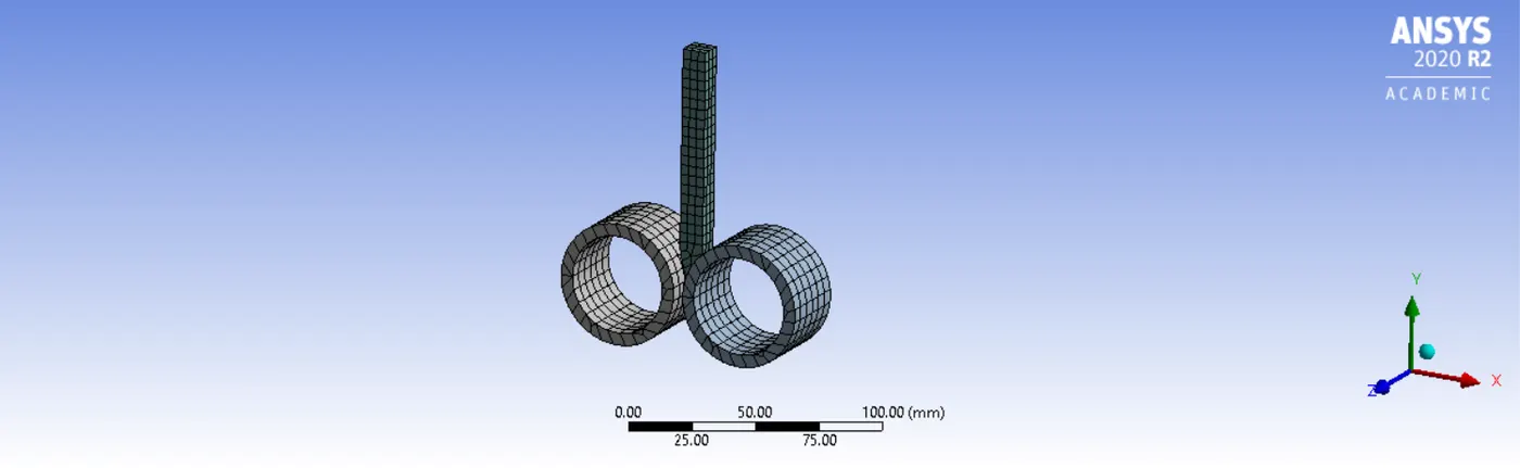
Fig 11: Mesh
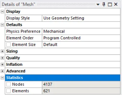
Fig 12: Mesh statistics
Analysis Settings
The settings for the number of steps of 14s, and it is the non-linear problem so the large deflection is ON.
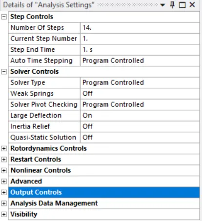
Fig 13: Analysis settings
For displacement as per the question mention, the piece is displayed for 90 mm at step 1 (0), steps 2 (-3), step 3 (-13), and for the steps adding a value of 7 to each and each value is going to (-Y) axis.
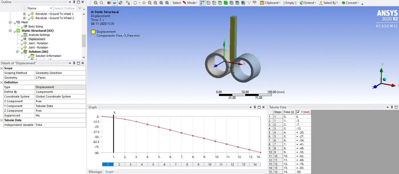
Fig 14: Displacement
The two joints are provided to rotate in the opposite direction with rotation value with an increase at each step about 15 degrees.
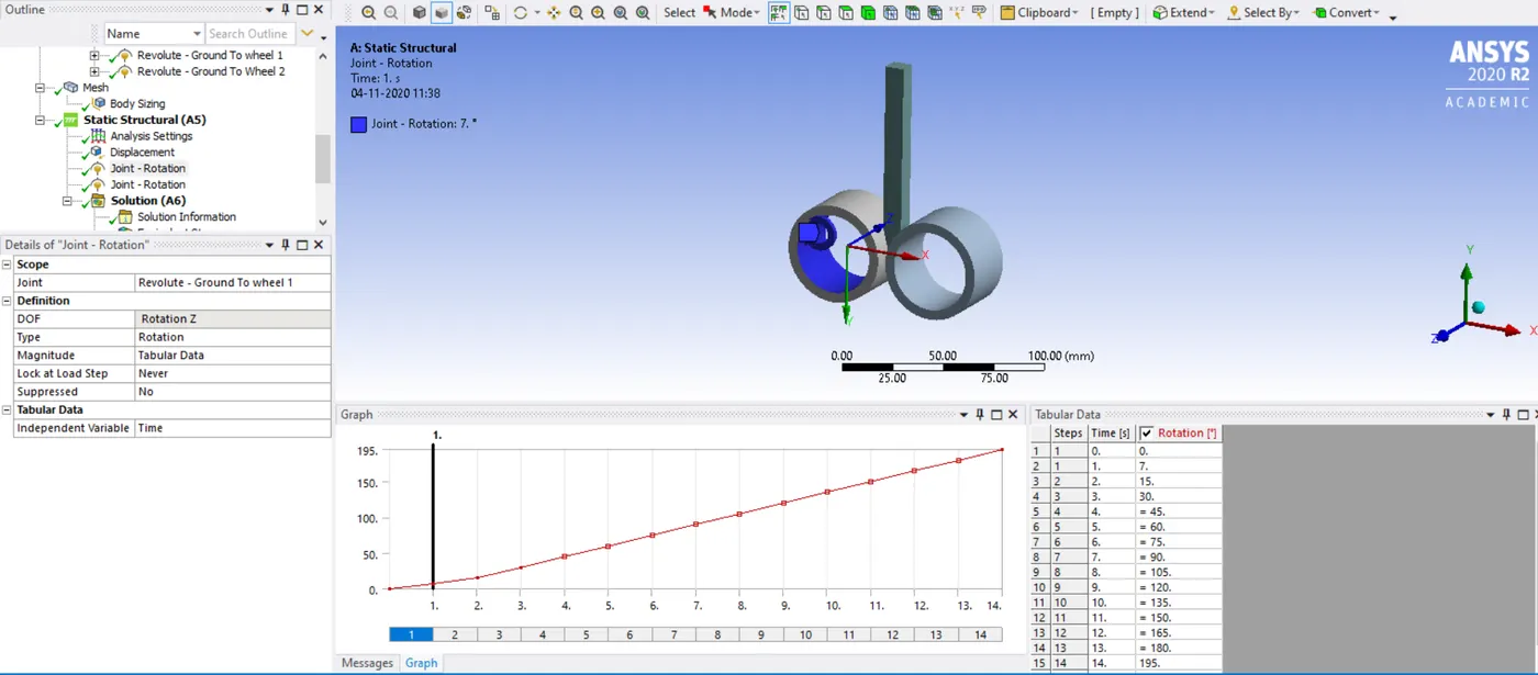
Fig 15: Joint -Rotation

Fig 16: Joint rotation 2
RESULTS
Equivalent von mises stress
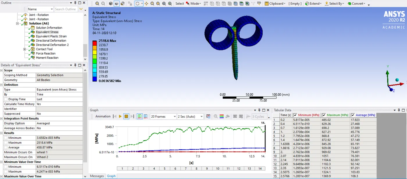 Fig 17: Equivalent stress
Equivalent Elastic Strain
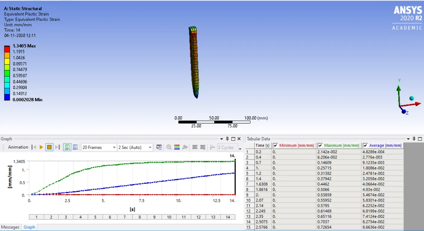
Fig 18: Equivalent elastic strain
Directional Deformation
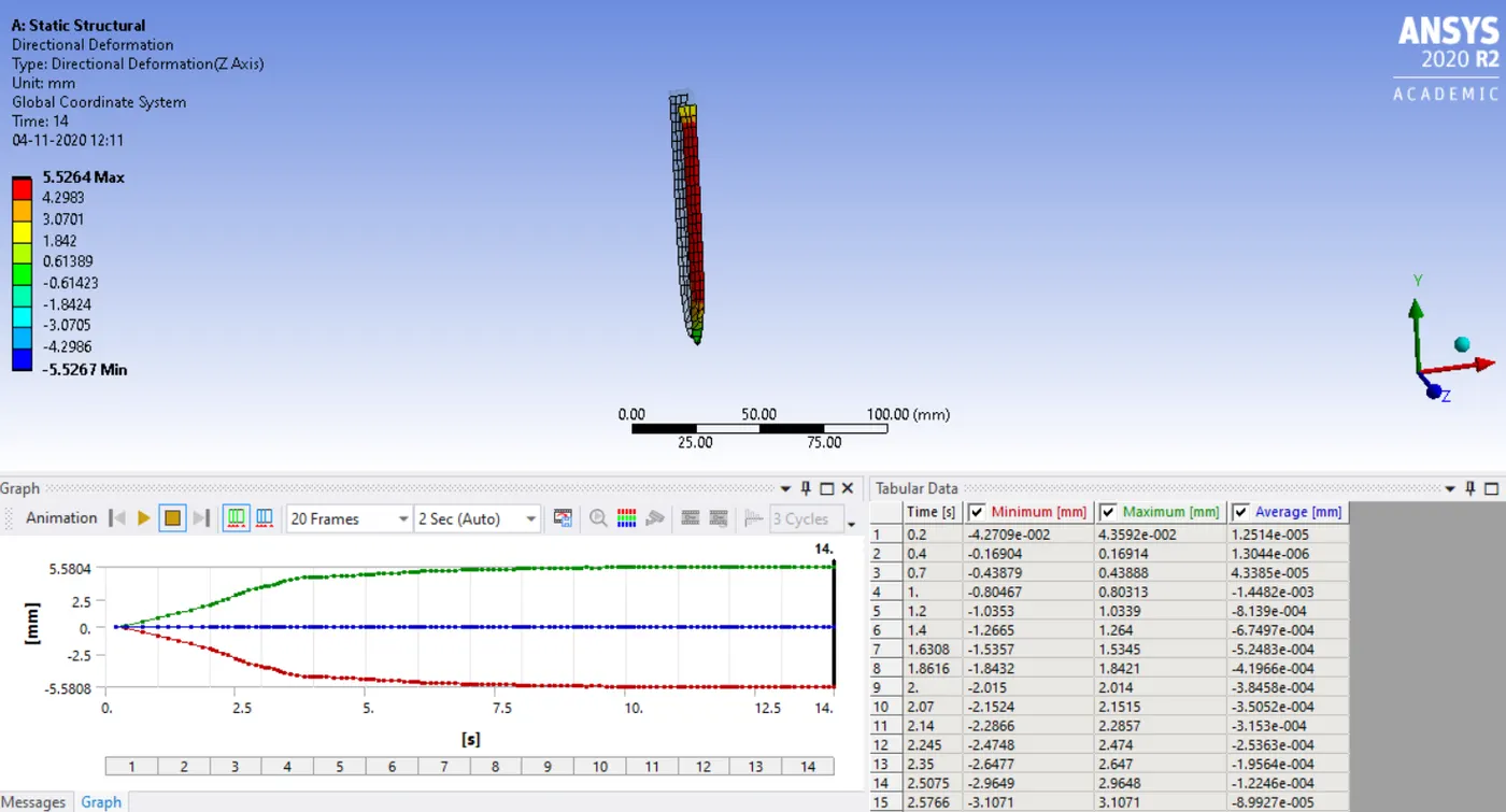
Fig 19: Directional deformation
Direction Deformation for 90mm
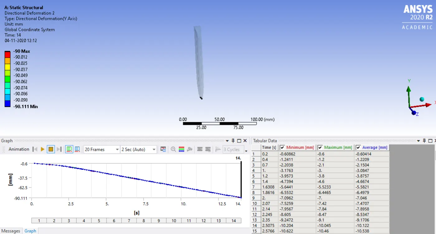
Fig 20: Directional Deformation 2
The above results show that the piece is moving directionally to Y-axis about 90mm and deforming up to min -90.11 mm, max -90 mm, and average -90.052mm.