ANSA Project 2: Mid surface, modeling, and connection on rear suspension gear
Project 2: Mid surface, modeling, and connection on rear suspension gear
AIM:
To extract the mid surface, modeling the component with given quality parameters and make the proper connections.
OBJECTIVE:
Rear suspension gear is given for the modeling in project 2, the component has a solid part with no uniform thickness, a shell part with uniform thickness, for both of them the quality parameters are provided. Including the Rim and Tyre with different quality parameters.
Components of suspension gear to mesh with tria and mixed elements and then need to give exact connect with RBE2 and RBE3 connections.
Quality parameters for all the components are:
Tyre and Rim:
| Sr.No | Quality criteria | Value |
| 1 | Target/Average length | 6.5 |
| 2 | Minimum Length | 5 |
| 3 | Maximum Length | 10 |
| 4 | Skewness | 45 |
For mid surface only (Mixed elements):
| Sr.No | Quality Criteria | Value |
| 1 | Target length | 4 |
| 2 | Minimum Length | 2 |
| 3 | Maximum Length | 6 |
| 4 | Aspect | 3 |
| 5 | Warpage | 15 |
| 6 | Skewness | 45 |
| 7 | Jacobian | 0.7 |
| 8 | Minimum quad angle | 45 |
| 9 | Maximum quad angle | 135 |
| 10 | Minimum Tria angle | 30 |
| 11 | Maximum Tria angle | 120 |
For another component (Tria):
| Sr.No | Quality Criteria | Value |
| 1 | Target Length | 4 |
| 2 | Minimum Length | 2 |
| 3 | Maximum Length | 6 |
| 4 | Skewness | 45 |
| 5 | Tet collapse | 0.2 |
Following the above quality criteria, each component should be modeled and connected properly for the simulation process.
SUMMARY
Rear suspension gear has many components attached such as the rim, Tyre, gear, disc, steering assembly component with the shaft and etc. those components to be visualized properly and mesh according to quality parameters. To achieve each component they should be selected by iNot option following the PID region to visualize, and then need to be measure with given parameters and to model them accordingly.
Each component has a different thickness and they are non-uniformed, as mentioned in the question the thickness above 5mm and uniform surface should be mesh with tria elements considering the solid part expect the length below 5mm and uniform thickness to be mesh with mixed type elements and getting the mid surface respectively.
"Solid part to be volume meshed"
PROCEDURE
Importing the Rear suspension file in the ANSA preprocessor, and deploying the meshing with appropriate Topology and geometry checks on each part.
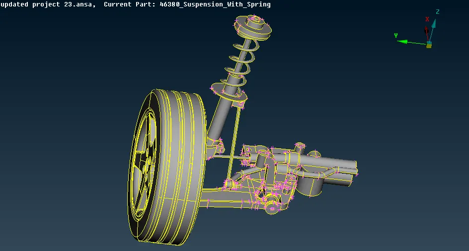
Fig 1: Suspension with spring
Before deploying the mesh on whole components, each part has set with different quality criteria, so for Tyre and trim, length has been set to 6.5mm as the target value by given perimeters and macros value and then checked for the geometry errors.
By checking the geometry there are few errors on the surfaces that are fixed auto or manually.
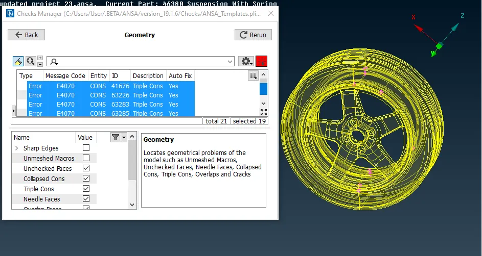
Fig 2: Geometry error Trim and Tyre
Those errors are fixed by auto option and manually, by getting the proper surface, as their trim and Tyre has thickness above 5mm and they are solid components so they mesh with tria elements, so to active exact result, components are compared and deployed with batch mesh and manual mesh, as for this component Batch mesh has linear mesh on both parts.
The batch mesh has setup with exact value, contents, and quality parameters
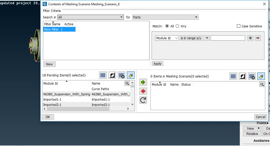
Fig 3: Batch mesh scenario case
After deploying the batch mesh, some of the elements are failing for minimum and maximum length which are fixed with the MOVE option.
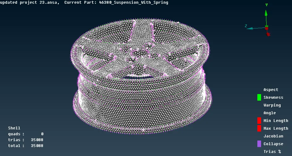
Fig 4: Trim quality output
Those shell elements are deployed for volume mesh because they are a solid component. The Solid PID is created and mesh with TETRA rapid option.
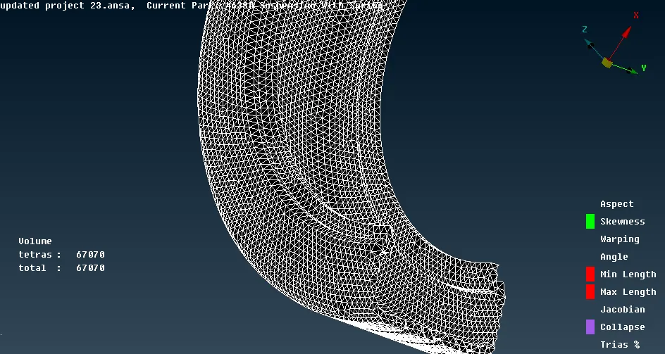
Fig 5: Volume mesh on Tyre
Other assemblies of the rear suspension, is separated with the PID region as creating the lock view for each of them to visualize and optimize the mesh on each part. After separating, the component they Named as suspension PART 1 to Part 12.
To optimize the mesh and first considering them as solid or shell parts. Part 1 is a solid part taking the measurement of thickness which exceeds above 5mm and the surface is non-uniform.
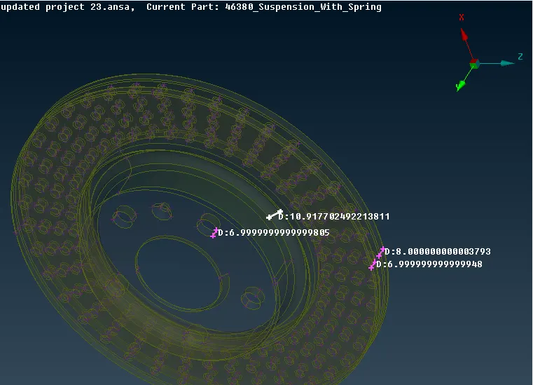
Fig 6: Measurement part 1
The component meshes with a manual process to deploy the tria elements on it and checked with the failing elements for quality criteria, for some of the small surfaces the defeature to obtain proper mesh. But to have exact results and fix quality issues some of the elements are not capturing the feature line but it except in the rear case.
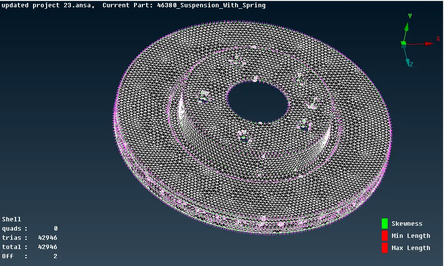
Fig 7: P1 mesh (Tria)
Deploying the tria elements on the part, it is the solid part it has to be mesh with volume, to deploy the volume mesh the solid PID is created and mesh with tetra rapid.
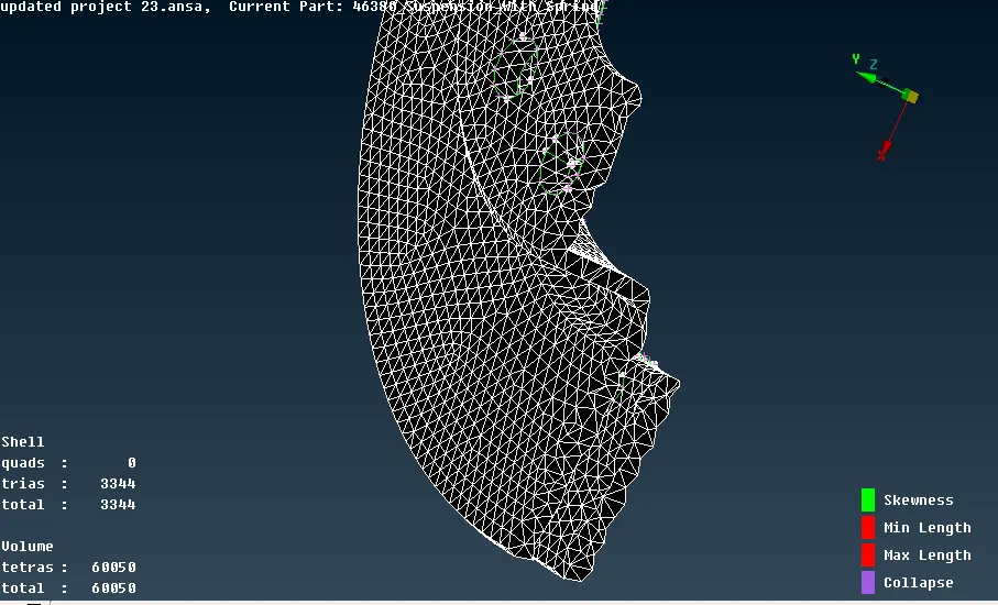
Fig 8: Part 1 Volume mesh
The part is also exceeding the thickness size but it has teeth that definitely fail for minimum length, so teeth are deleted and created with a plane surface.
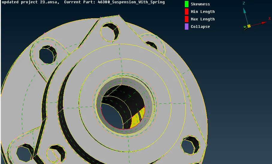
Fig 9: P2 deleting teeth and creating the plane surface
This part is also meshed manually to achieve the exact results and mesh and then mesh with the volume mesh option with creating solid PID.
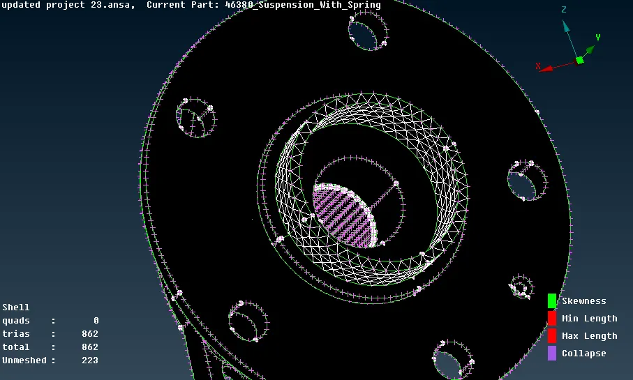
Fig 10: Manual mesh on part 2
Creating the solid PID for the part 2 component and the meshing it with tetra rapid option to obtain the volume mesh on it.
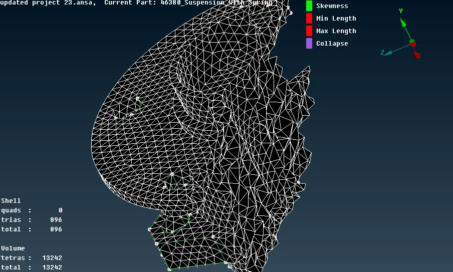
Fig 11: Part 2 Volume mesh
Deploying the volume mesh on the above component, there is not tet collapse that is found till yet. Mesh flow is good with given quality parameters and tet collapse value.
Measuring their part, as part no 3 the surface is nonlinear and the value is above 5mm. The component is a solid part.
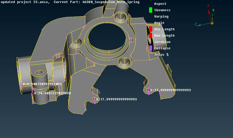
Fig 12: Part 3 Measurement
The component large part of the assembly, to minimize the time and deploy the mesh, this component performed with manual mesh, as the mesh is deployed on it.
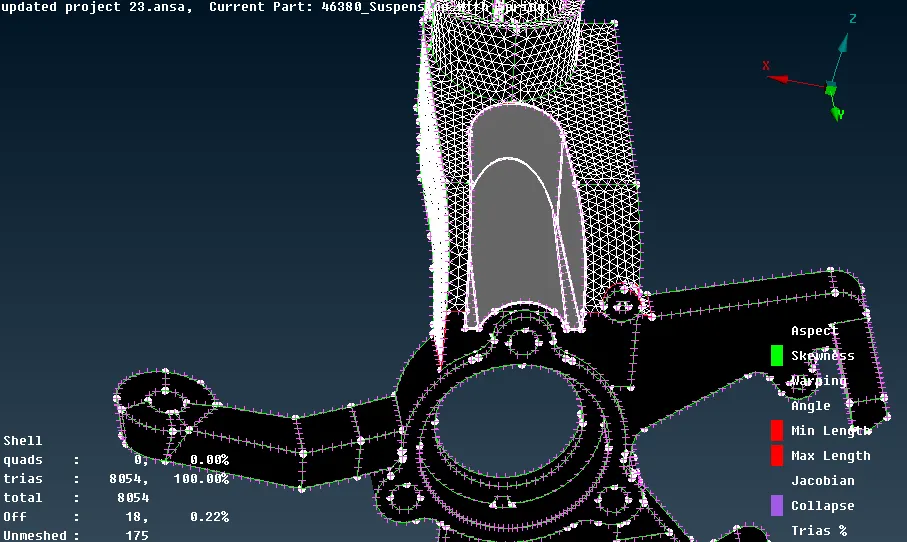
Fig 13: Part 3 spot mesh
For volume mesh, the same procedure is followed to obtain the solid part.
Now the part 4, it has uniform thickness with the cylinder and small plate attached to it, this component can be extracted with the mid surface, by given the offset value. First measure the thickness of the component
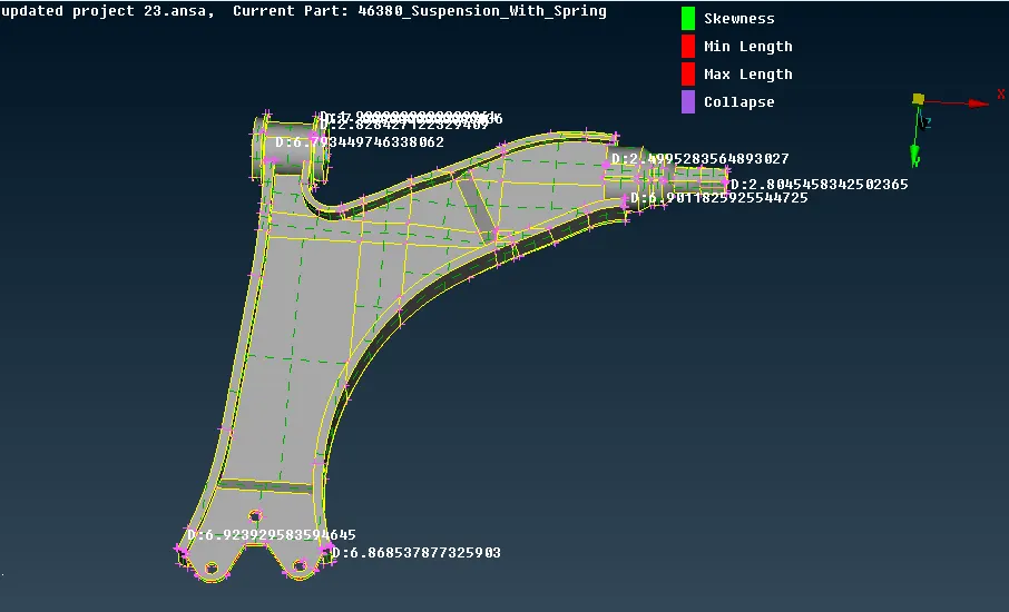
Fig 14:Measurement part 4
After extracting the mid surface, the part is assigned to the property with a given thickness value.
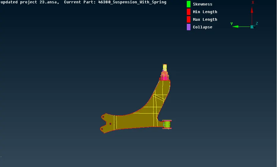
Fig 15: Part 4 Thickness assigned
For deploying the manual mesh on it, this component is set with different quality parameters and then meshing it with mixed type elements but this time the different algorithm is followed, (BEST) option. And the mesh flow result is better.
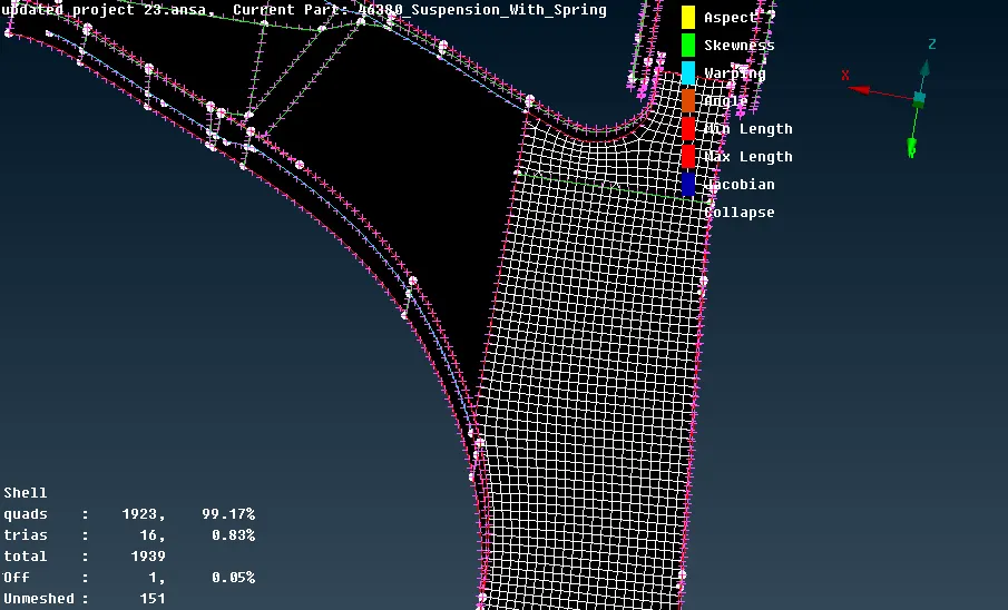
Fig 16: Mesh on part 4
Fixing the quality output by reconstructing option or smoothing the elements by selecting macro-region.
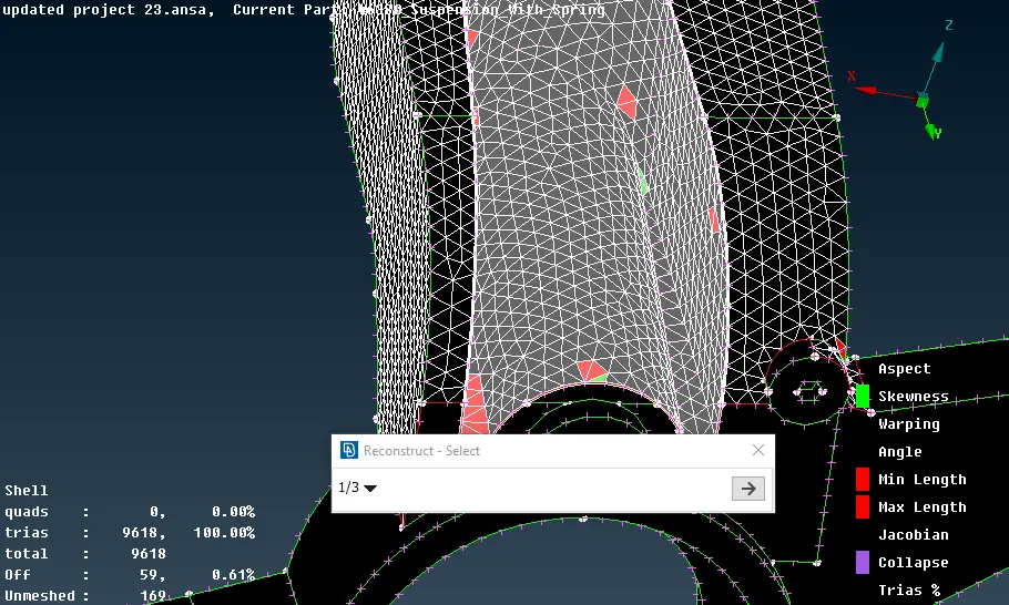
Fig 17: Reconstruct error part 4
Shell Parts
The shell parts which need to take the mid surface out of the parent geometry, the thickness of the part is below 5mm and have linear surface overall which is part 12, and part 19.
For part, the surface has a thickness of around 3mm respectively.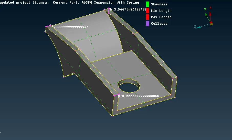
Fig 18: Part 12 Measurement
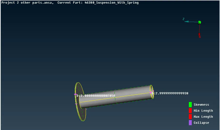
Fig 19: Part 18 measurement
After taking the thickness measurement, the component is offset with a given value to obtain the mid surface of them.
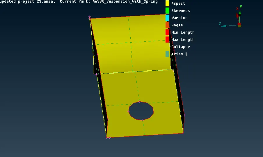
Fig 20: Part 12 mid surface
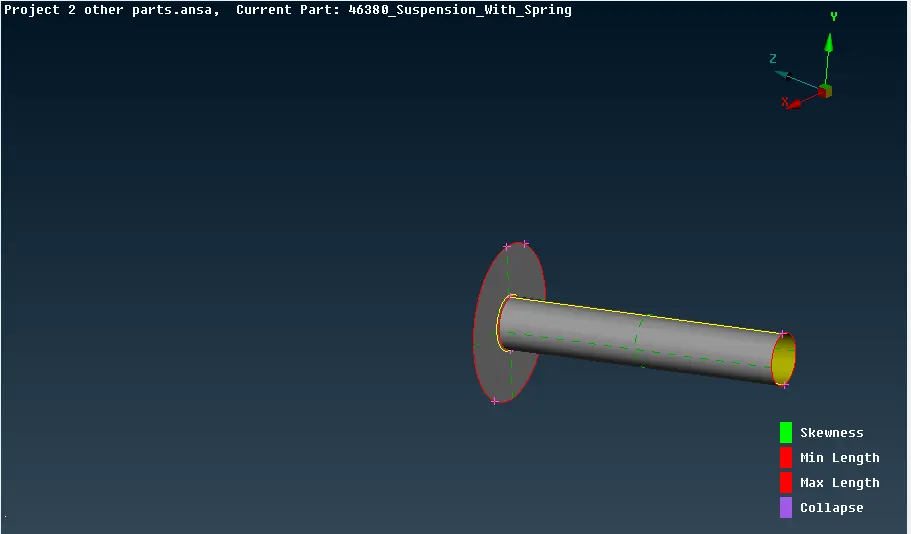
Fig 21: Part 19 mid surface
Both of the surfaces are deployed mesh by them elements size 4mm and the BEST algorithm is used to obtain the proper mesh flow on them whereas, the surfaces with small size are defeatured, so it should not fail for the minimum size error.
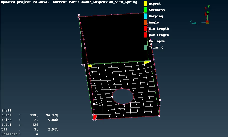
Fig 22: Part 12 meshing
The failing elements are fixed with reconstruct option or smooth to fix the issue and deploy smooth mesh flow.
Solid parts
Other parts such as suspension parts 5, 6, 7,8, 9, 10, 11, 12, 13, 14, 15, 16, 17, and 19 have a non-uniform thickness as checking the thickness of them by the measurement option.
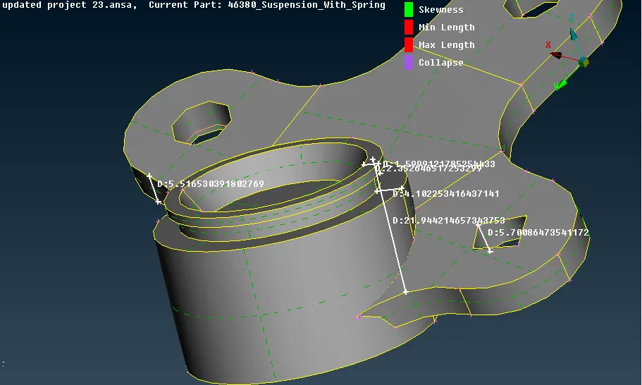
Fig 23: Measurement part 6
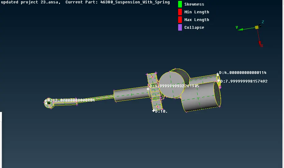
Fig 24: Measurement Part 7
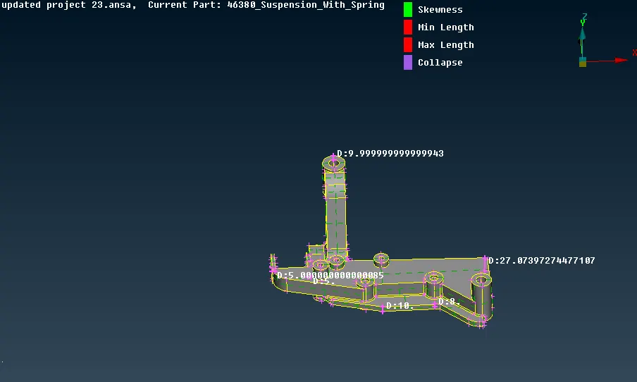
Fig 25: Part 8 measurement
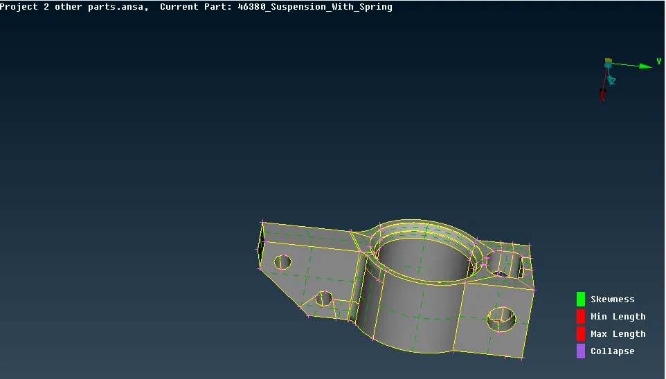
Fig 26: Part 9 Measurement
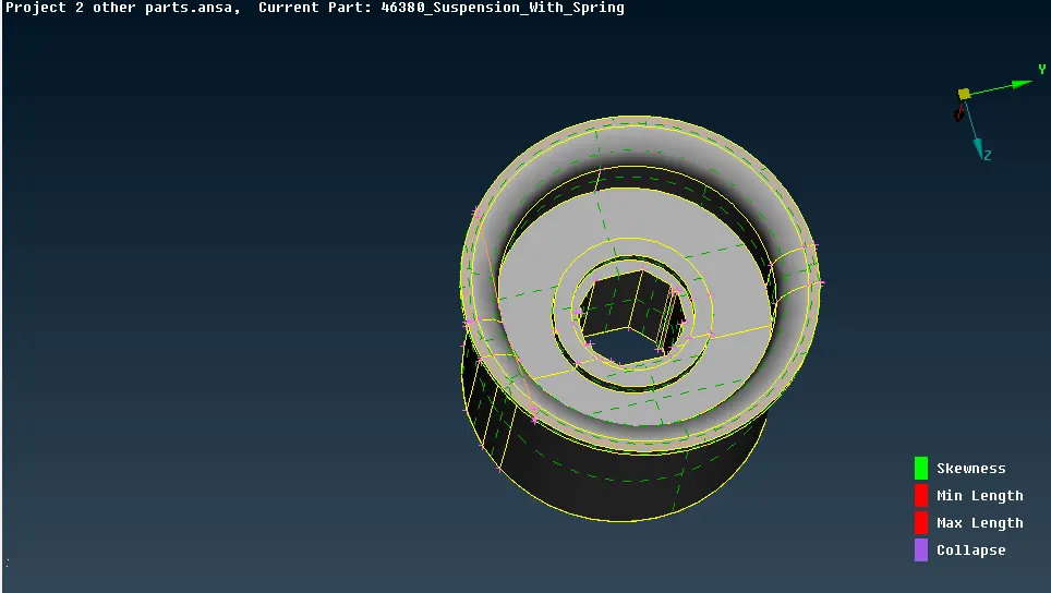
Fig 27: Part 13
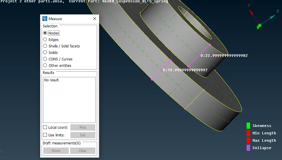
Fig 28: Part 14 measurement
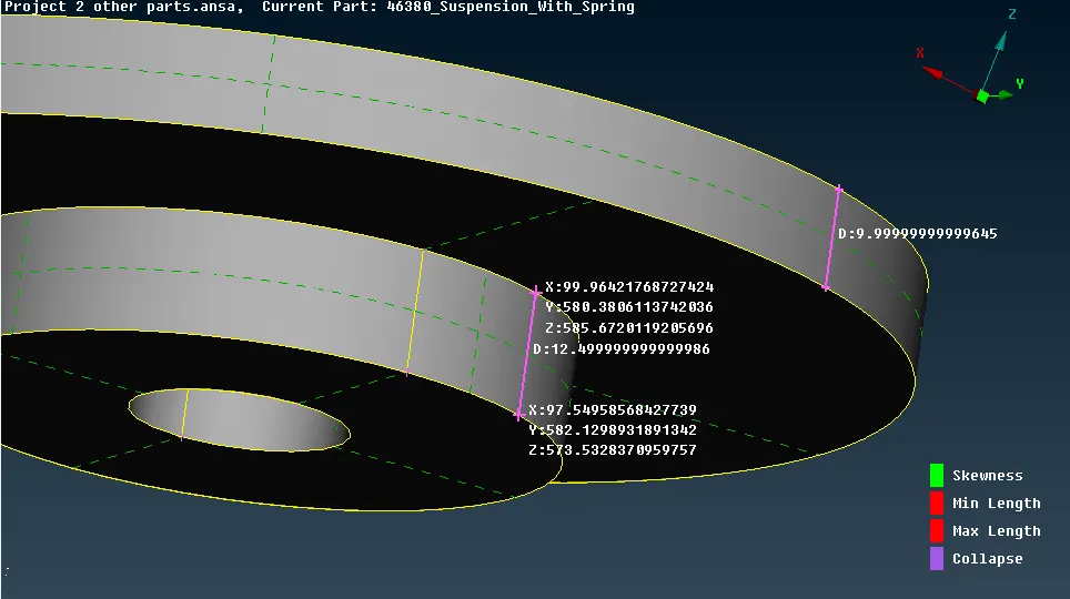
Fig 29: Part 15 measurement
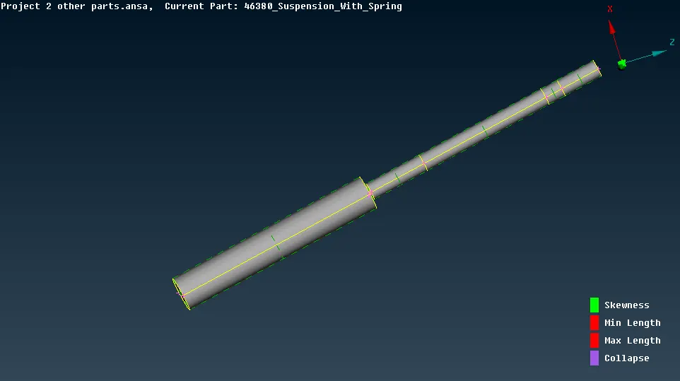
Fig 30 Part 16
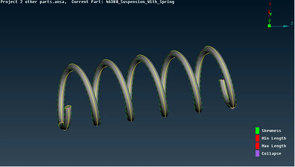
Fig 31: Part 17 spring
Fig 32: Part 18 measurement
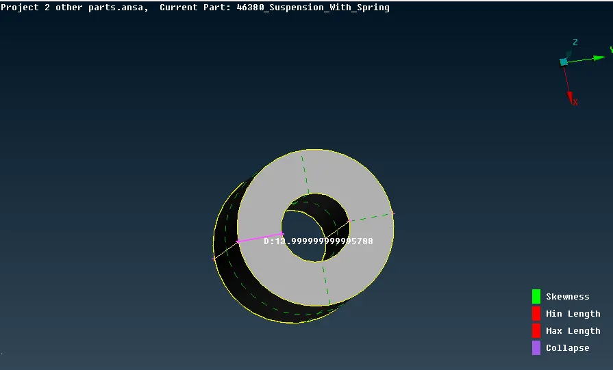
Fig 33:Part 19
All the parts considered to be solid components as checking with the geometry errors and fixing them manually or auto option. This component deployed with the spot mesh option using 4mm element size and the batch mesh option.
Giving the exact value and quality parameters to the batch mesh, this auto meshing process has better mesh flow on some component and the other is mesh manually.
The errors won batch mesh are negligible and corrected them manually
Also, the manual mesh flow has some failing elements for skewness, minimum size, and maximum size they are corrected.
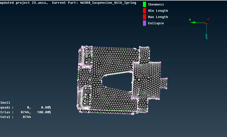
Fig 34: Part 5 Batch Mesh
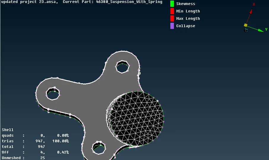
Fig 35: Part 6 Spot mesh
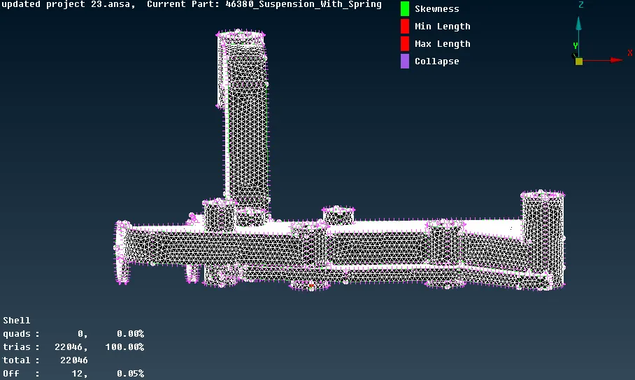
Fig 36: Part 8 Batch mesh
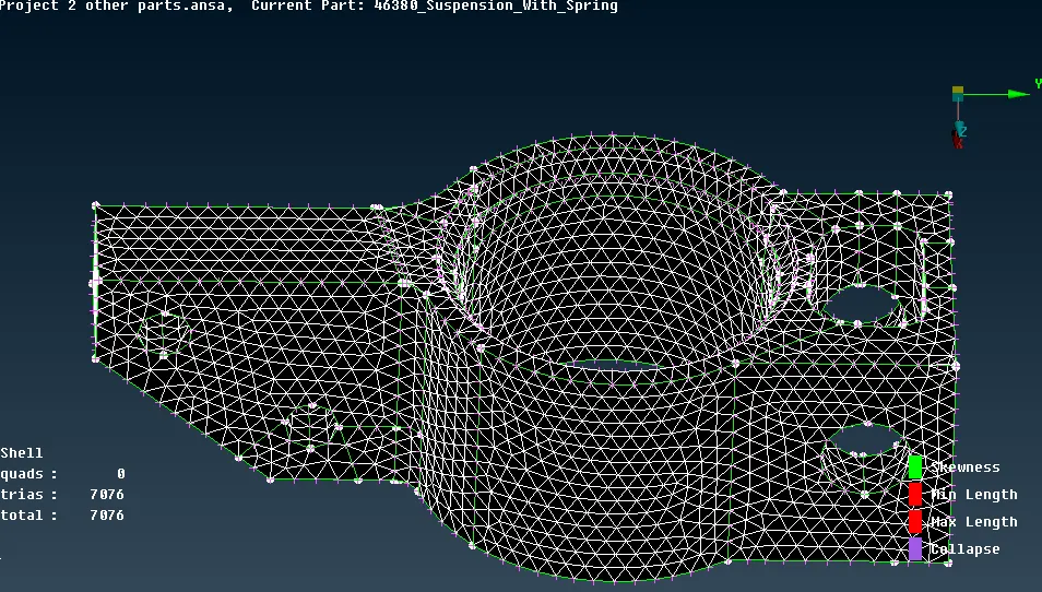
Fig 37: Part 9 spot mesh
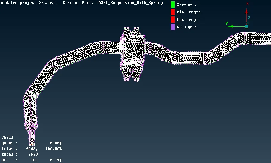
Part 38: Part 10 Spot mesh
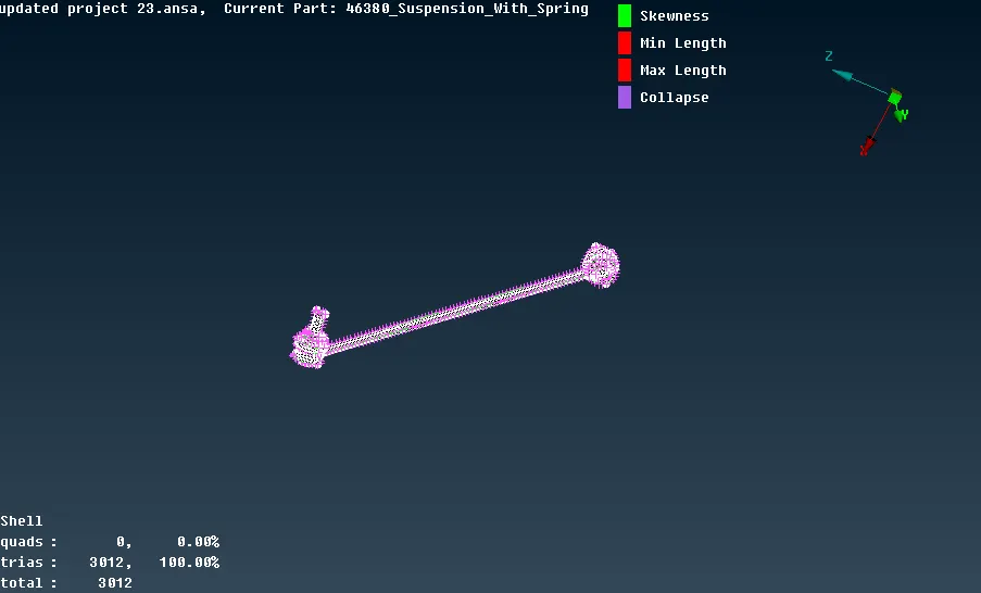
Part 39: Part 11 Batch mesh
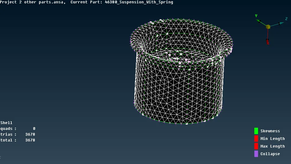
Fig 40: Part 13 batch mesh
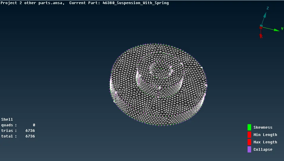
Fig 41: Part 14 spot mesh
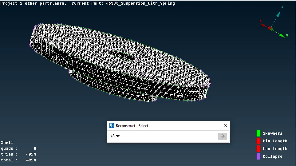
Fig 42: Part 15 spot mesh
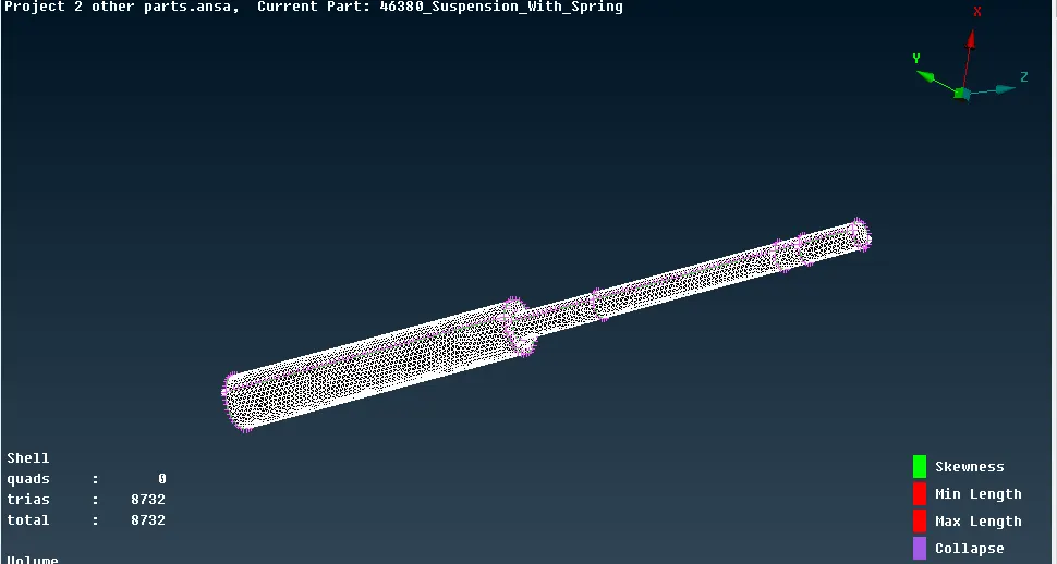
Fig 43: Part 16 spot mesh
After deploying the batch mesh and Spot mesh on the component, the volume mesh is deployed on the component by creating the PID and then mesh with the tetra rapid mesh. The volume mesh has the tet collapse error those are fixed with the move option.
But most of the volume components have not tet collapse error.
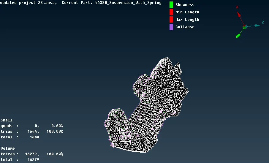
Fig 44: Part 5 Volume mesh
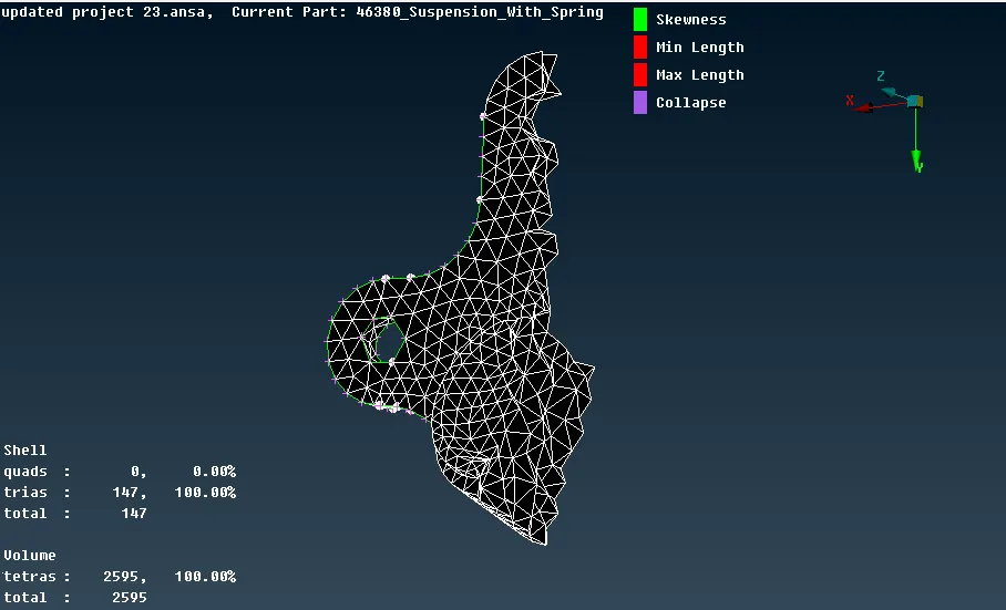
Fig 45: Part 6 Volume mesh
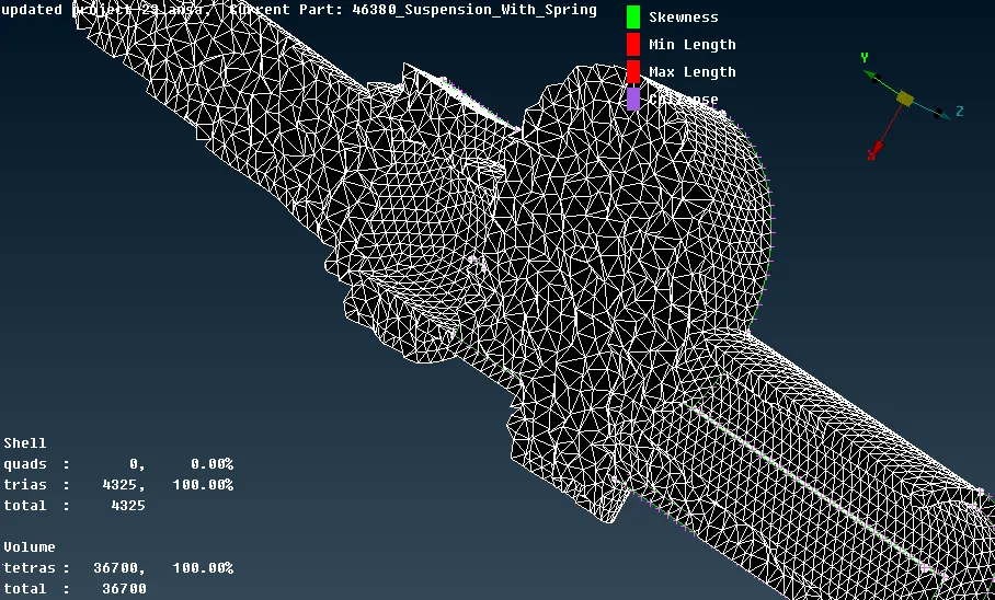
Fig 46: Part 7 volume mesh
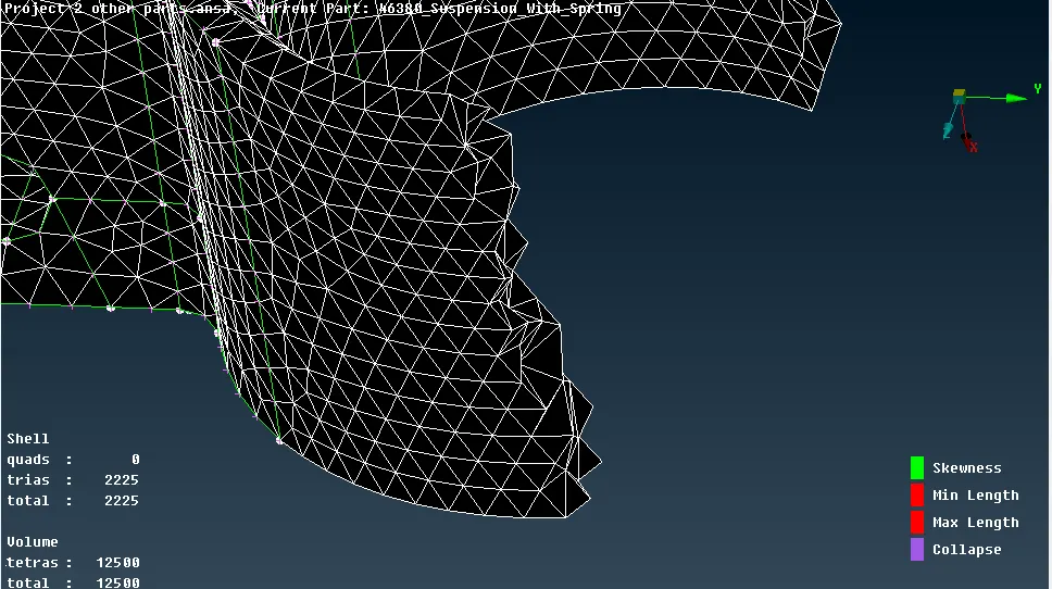
Fig 47: Part 9 volume mesh
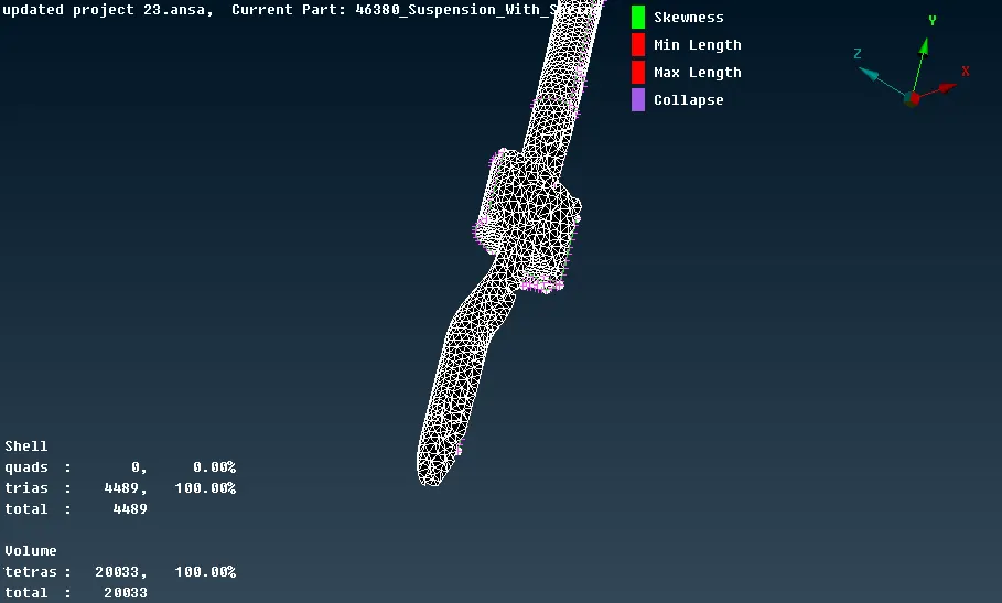
Fig 48: Part 10 volume mesh
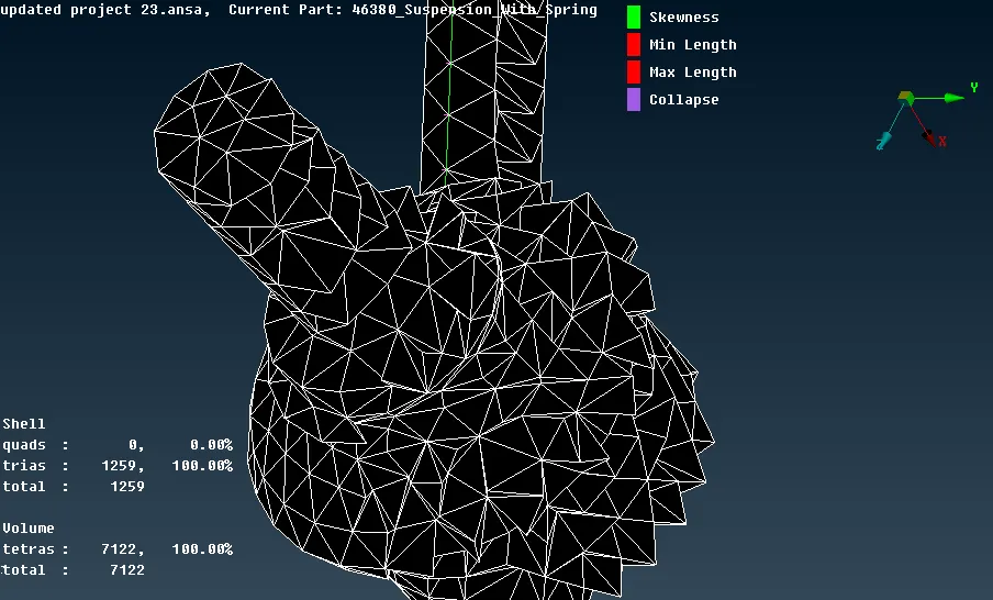
Fig 49: Volume mesh on part 11
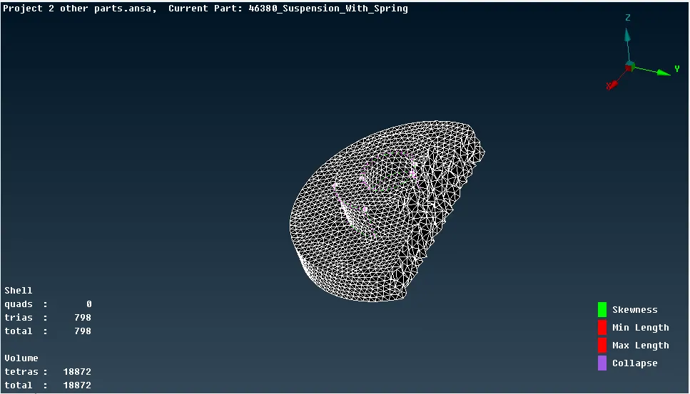
Fig 50: Volume mesh part 14
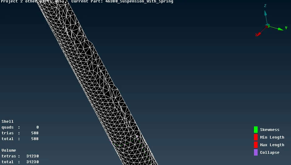
Fig 51: Part 16 volume mesh
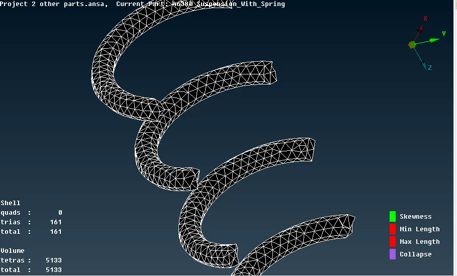
Fig 51: Part 17 volume mesh
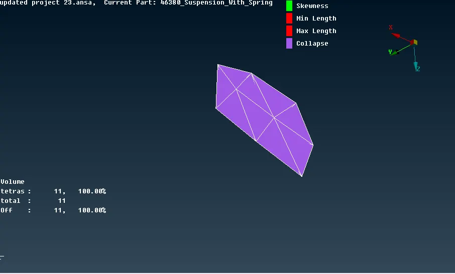
Fig 52: Fixing tet collapse
Connections
The various types of connection can be made on the assembly, as there as sub-parts for the rear suspension and they are connected with RBE2 bolt connection, tow node connections between them.
These connections made as cluster RBE2 elements, RBE 2 single connection, and for the two surfaces 2 node connections.
These connections are shown in figure detail.
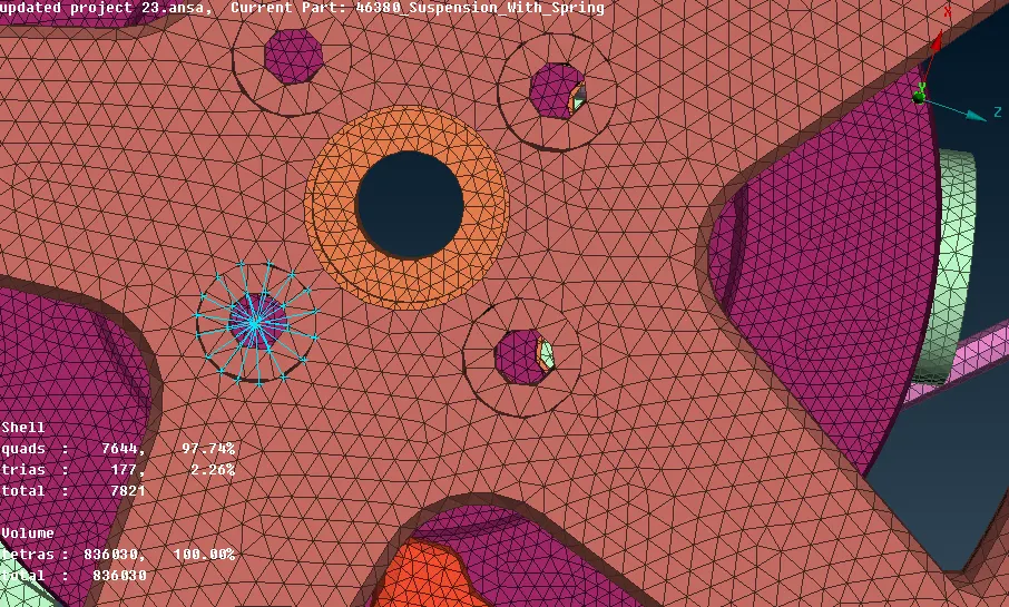
Fig 53: RBE2, cluster and 2 nodes
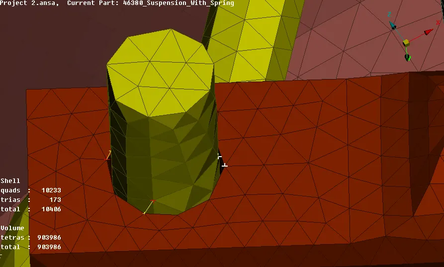
Fig 54: RBE2 two-node connection
RESULTS AND CONCLUSION
The Rear suspension has many subparts as they are selected individually and they mesh accordingly, the shell parts mesh with shell with mid surface and solid parts with tria elements and then volume mesh as these parts is tried with auto (Batch mesh) option to check the quality of mesh which seems to proper on the surfaces.
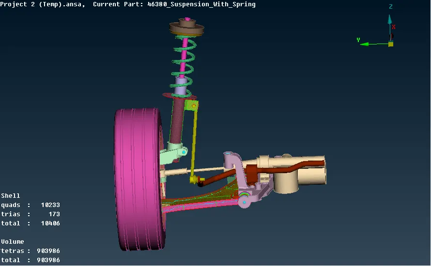
Fig 55: Rear suspension modeled
And the connection is properly deployed where ever possible on the component with RBE 2 cluster and two-node option.
Making the geometry symmetry and as they are not connected properly with each other so the RBE2 connection is given between both geometry and mesh.
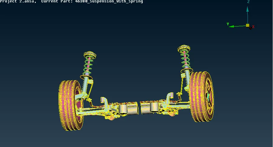
Fig 56: Symmetrical model
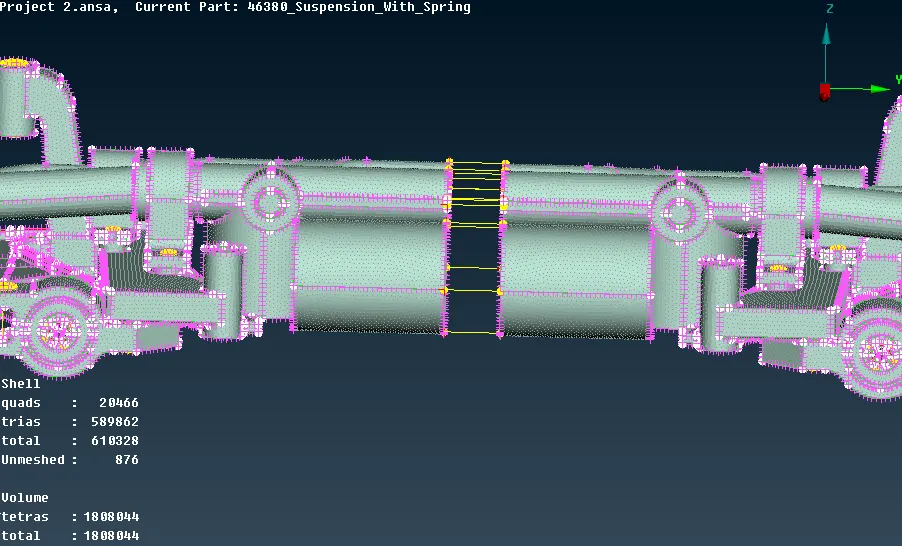
Fig 57: Symmetrical geometry two node connection
RECOMMENDATIONS
The assembly can be select into to individual part by selecting the PID region and then lock them as each part, also the Batch mesh option gives proper mesh flow on some components.