Hypermesh Challenge_6 - Midsurface extraction, Meshing, Quality criteria and assign
Challenge 6 - Midsurface extraction, Meshing, Quality criteria and assign Thickness
OBJECTIVE:
To mesh the hood component on mentioned quality criteria and assign thickness to the component, five parts of the hood should be extracted with midsurface doing manual geometry cleanup and meshing with quality criteria and their mentioned value.
| S.N | Quality Criteria | Value |
| 1 | Aspect Ratio | 5 |
| 2 | Skewness | 45 |
| 3 | Warping | 15 |
| 4 | Taper | 0.5 |
| 5 | Min. Length | 2mm |
| 6 | Max. Length | 8mm |
| 7 | Min angle Quad | 45 |
| 8 | Max angle Quad | 135 |
| 9 | Min angle Tria | 20 |
| 10 | Max angle Tria | 120 |
| 10 | Tria % | 10 |
PROCEDURE:
Hood component has five different parts to assure the separate midsurfacing on each part and their mesh quality:
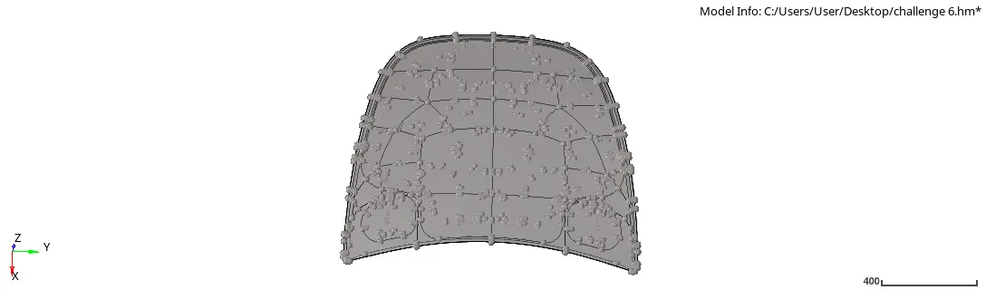
Fig 1: Hood component
Latch reinforcement
- Assigning the latch part for further quality criteria process, firstly delete the solid parts of latch reinforcement from delete command selecting the surface and delete it.
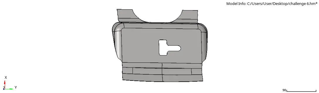
Fig 2: Latch reinforcement
- After deleting the solid part, extract the midsurface of the latch reinforcement, ensuring the extraction option (offset+plane+sweep), and select the surface and extract midsurface.
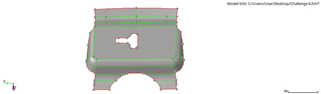
Fig 3: Latch midsurface
- Extracting the mid surface of latch component, there are errors to fix before the meshing for that manual geometry cleanup need to be done, the edges of top hole to be fixed with quick edit "trim intersect" node to node select and trim it, then at fillet shared line to be toggled with .05 unit tolerance to have suppressed line.
- Once we cleared with edges and surface to toggled, to catch the proper meshing need to add washer split at the circle by the offset value of 5 mm.
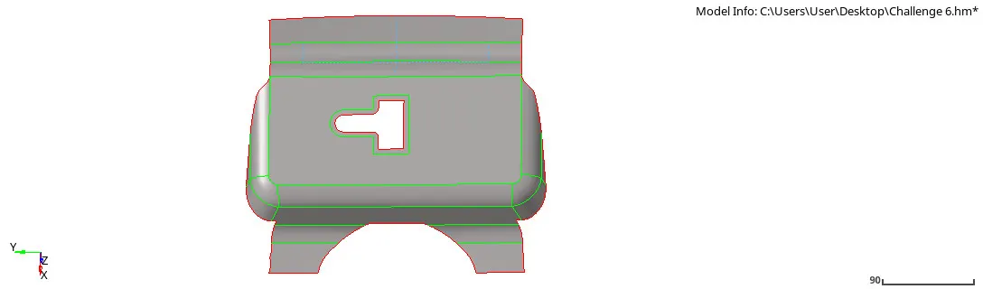
Fig 4: Latch geometry cleanup
- Performing manual geometry cleanup on the component, check with all edges, points, duplicates, missing surfaces, and suppressing the line. Now meshing the component with the element size = 5mm and element quads for rectangular surface and mixed for other surfaces.
- Quads on rectangular perform well and other side mixed elements are appropriate. Increasing or decreasing the node on the elements to remove tries and rotational elements.
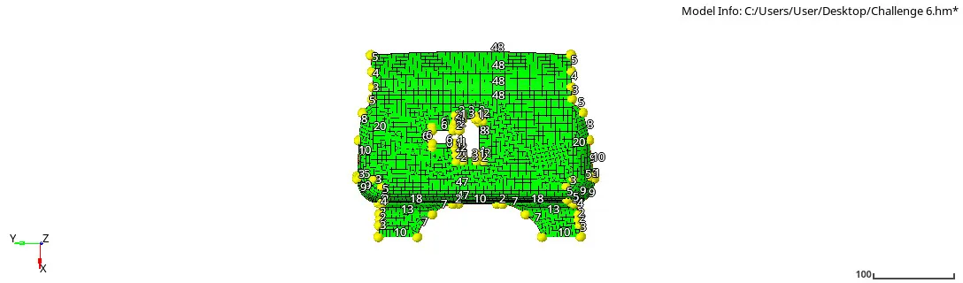
Fig 5: Meshing on Latch component
- Before removing the trias need to understand the trias management to follow for quality criteria:
1 Trias concentration:- Trias element (reduce) 2 Number of trias (Below-quality criteria)
3 Number of trias on the corner or edges 4 No opposite trias 5 No back to back trias 6 No trias on fillets and hemming 7 No rotational quads 8 No trias should share a boundary with the feature line
9 Split and perform the mesh
- Remove trias and rotational quads as much can able to remove from the mesh, which are unable to do that can be done by re-mesh the process to specific elements again, possible it can remove the trias by increasing the node or decreasing it. wherever possible the option can be used to remove the trias:- Replace the nodes with other nodes, split the nodes and combine the split section, and smooth the elements. Possible to eliminate all possible trias but minor can be removed from quality index option in 2D.
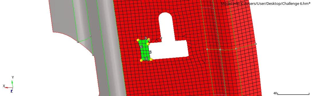
Fig 6: Re-mesh to remove trias and rotation quads
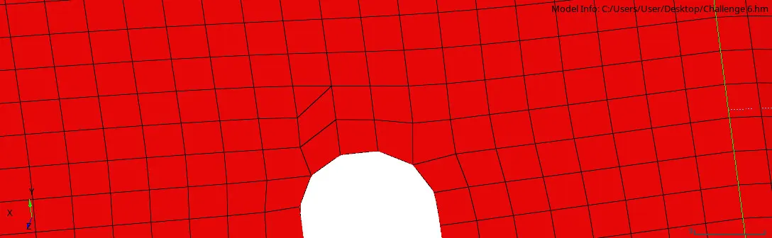
Fig 7: Split elements
- Removing possible trias and rotational quads after re-mesh and other options, now to check the quality criteria from the quality index in the 2D
- Quality Index has many criteria that are mentioned in the objective, those values to be inserted in the "preferences + quality criteria settings". inserting values to have quality output and result through elements.
- Quality criteria have a different option to remove trias elements such as [place nodes, drag tria elements, combine tria elements]. Though this can be used to have elements under trias management.
- Other options are also used to optimize the elements, smooth elements, and node optimize, etc.
- The elements should be check under displayed thresholds, it displays the worst and fail elements that need to be repaired.
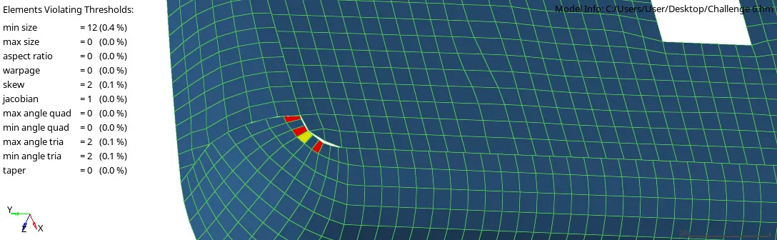
Fig 8: Quality index (Criteria)
- Remove the trias that can be removable, ensuring the smoothness of element, on the smooth command, other tools are available in the quality index that can be used to drag trias from one place to other, also raise can split and combine to move the trias.
- After checking the errors in the element fixing trias and rotating quads elements, also to ensure the edges are no in between the component rather than free edges.
- Such edges are found if there is no connectivity between the elements and can be fixed by replacing the nodes between two elements.
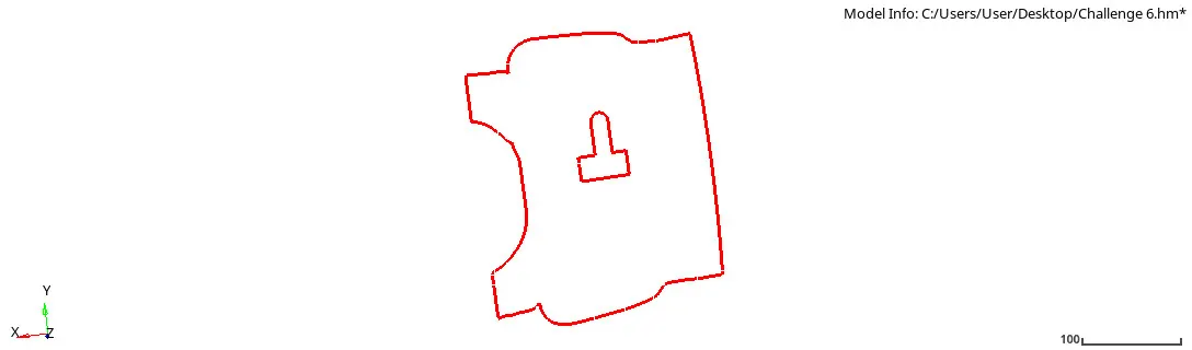
Fig 9: Edges of a latch part
- Clearing all edges to have perfect free edges on the part, checking the trias management, and finally, the quality criteria value to have the perfect part on the aspect of their quality consideration the result will show without 0% of errors in the element.
- To obtain 0% errors in the part after checking described values, now to assign the thickness and the material on the part [Thickness- 1.2mm and Material- steel].
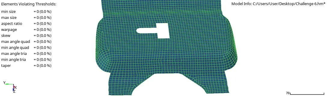
Fig 10: Latch Quality criteria result
Hinge body part 1
- Assigning the hinge body part 1 part for further quality criteria process, firstly delete the solid parts of latch reinforcement from delete command selecting the surface and delete it.
- Then extract the midsurface of the hinge and to start with the manual geometry cleanup, as doing cleanup no defects found in the part except the double green line between the fillets which has been toggles by 0.5 unit.
- Geometry cleanup is ready to have mesh on the hinge part.
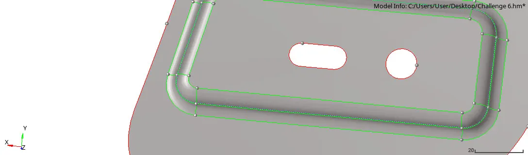
Fig 11: Hinge body 1 midsurface
Fig 12: Hinge body 1 geometry cleanup
- Extracting the midsurface and the fine geometry cleanup on the part, now to mesh the part with a mixed element and the size for elements are 5mm.
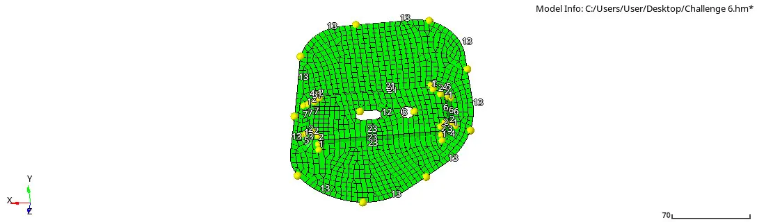
Fig 13: Hinge body 1 meshing
- Following the trias management rule, where possible to have perfect quads, increasing or decreasing the nodes on initial meshing, the opposite trias and rotational quads are meshed again to have perfect quads elements.
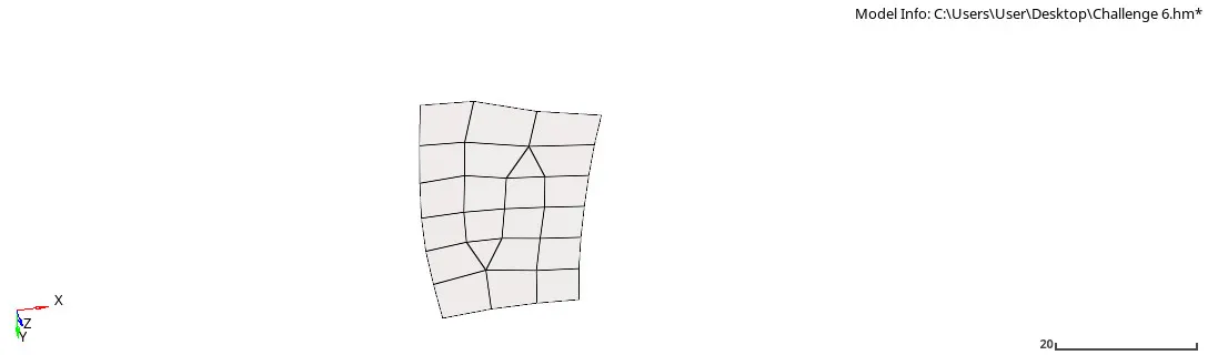
Fig 14: Hinge body 1 opposite trias re-mesh
- Trias that re unable to remove from edges that are shifted to the next element by splitting the element and combine the trias.
Fig 15: Split elements
- After optimizing the perfect quads, meshing at specific areas, and smoothing the elements to have the right elements segment, second to check the quality criteria by checking the fails elements in the geometry, the fail elements are corrected by the tools that are available in the quality criteria tools.
- The values of quality criteria are followed by the mentioned quality tables after putting values the certain errors found in the hinge body 1.
Fig 16: Hinge body 1 quality criteria output
- Those errors are fixed by removing the trias, other tools are also used such as fixing the node has given good element, splitting the quads, and shifting the trias, smoothing the elements to have correct element dynamics.
- And another tool was also useful such as the element optimizes.
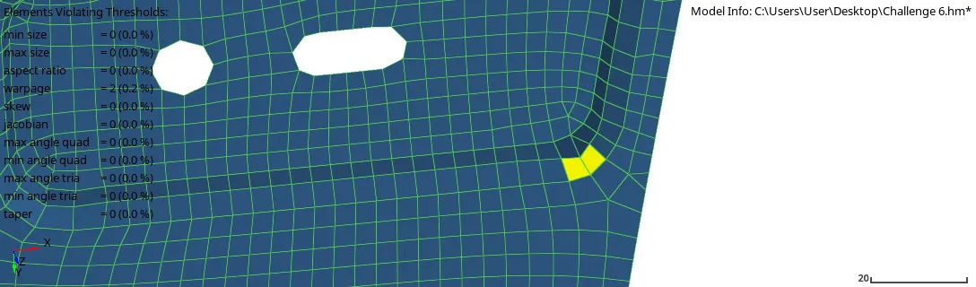
Fig 17: Element optimize hinge body 1
- Getting the elements to optimize and quality output at the final segment of hinge body 1 checking the edges that are shown in the geometry except for free edges.
- The hinge body 1 part has a quality element output.
- After getting the result, the quality value at given criteria the element is assigned to the material steel and the thickness of 1.2mm
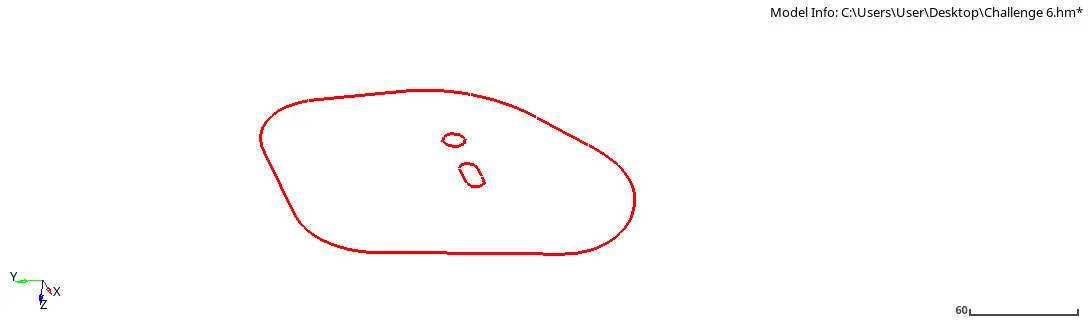
Fig 18: Edges on hinge body 1
Hinge body part 2
- The same procedure followed to the hinge body part 2, they have the same dimension and equal geometry to work on.
- Deleting the solid part of the geometry for further procedures.
- Extracting the midsurface of the hinge boy part 2 for geometry cleanup.
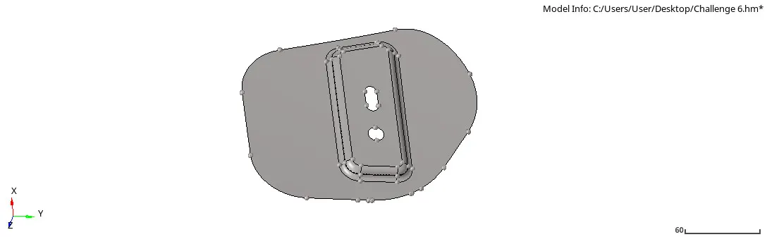
Fig 19:Hinge body 2 midsurface
- For the geometry Cleanup, not so more work to do on except the checking free edges and the shared lines on the Flemming is toggled by 0.5mm.
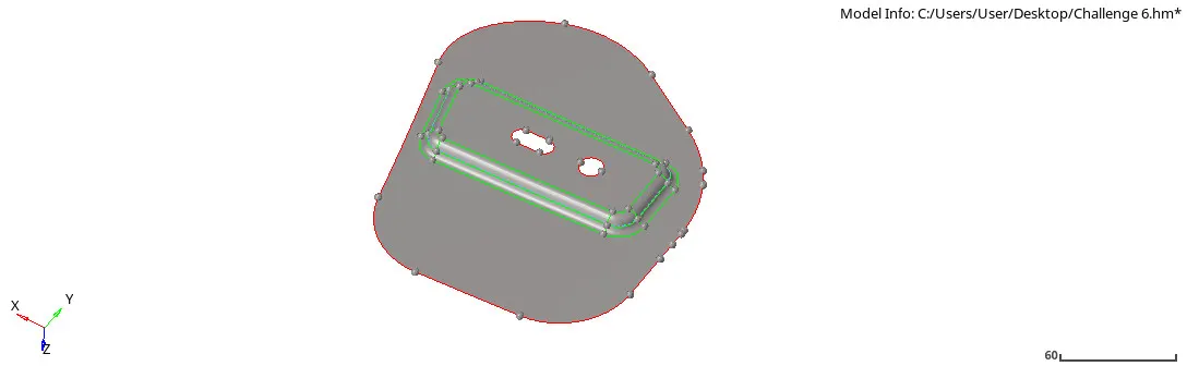
Fig 20 Hinge body 2 geometry cleanup
- Doing clear geometry cleanup for the meshing process, hinge body 2 is meshed by 5mm element size with all mixed elements.
- The possible trias and rotational quads at the circle part and rectangular cut part are avoided by increasing and decreasing the number of nodes.
- A proper mesh achieved to have further re-mesh process wherever the trias is unable to deceive at initial meshing, are now re-mesh again to avoid trias as per trias management rule.
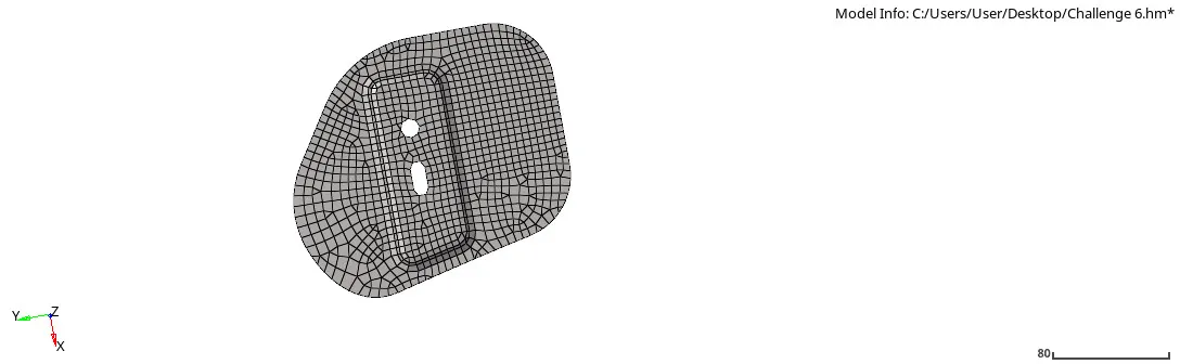
Fig 21 Hinge body 2 meshing
- The rotational quads, back to back trias, opposite trias are fixed by re-mesh or splitting the trias at end of edges are shifted by split command and perfect trias that are moved.
- Some elements are fixed by replacing the nodes for proper quads.
- In the end, the possible trias and rotational quads that have been fixed by the tools are now smooth all elements.
- Getting proper elements for quality check criteria, there found some fail elements that needed to fix.
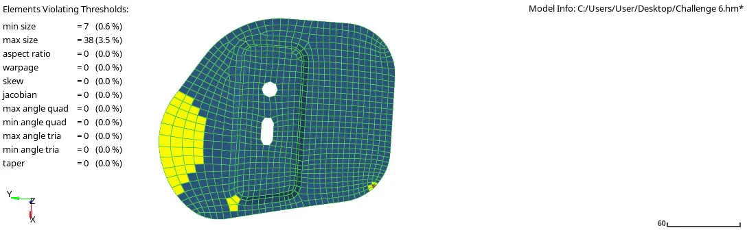
Fig 22 Hinge body 2 quality errors
- The element is fixed by removing the trias directly or by element optimize these parts also achieved by the same process to achieve neglect or the output at the given value of the quality criteria.
- The hinge body part 2 is checked for edges in between except the free edges, and finally, checked for the quality element output.
Outer extract body 1
- The outer extract body 1 is the large part of the component, the part has been deleted by the solid part.
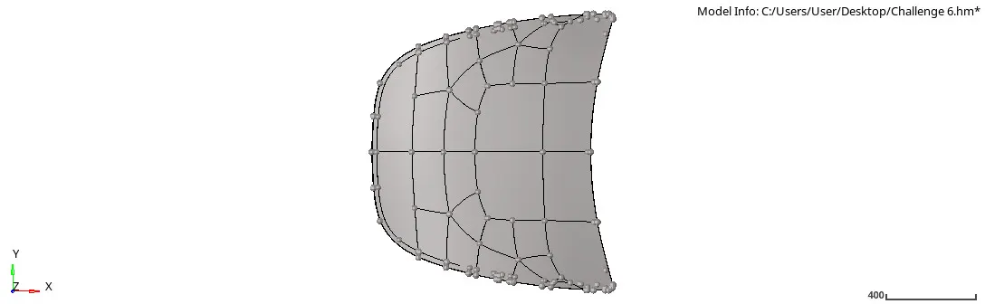
Fig 23 Outer extract body 1
- The part is extracted by the midsurface for the further geometry cleanup, the par has many points that need to be manual cleanup.
- Shared (Green) lines are between the surface which is toggled by the 0.5 unit. to have one single surface.
- Flemming part has some deformation that has been fixed by deleting a specific Flemming surface and again created to have perfect Flemming, also check suppressed the shared lines at the Flemming.
- The outer extract body 1 is done with Topology (Geometry) Cleanup.
- But the part is very large to mesh up some and clear all the trias, so the part is divided into half then into the rectangular section, to easy to handle trias and rotational quads and can be fixed the elements.
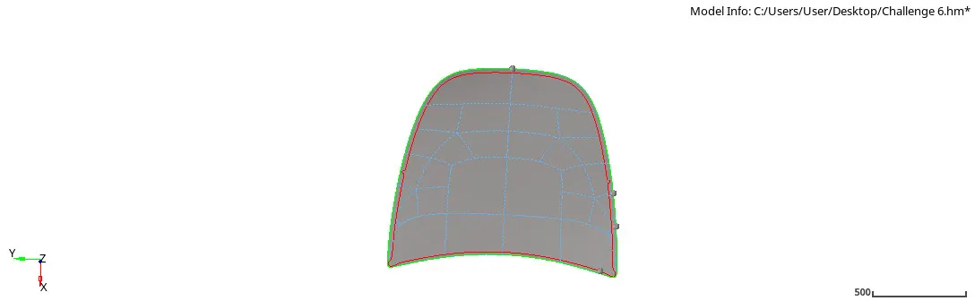
Fig 24 Outer body 1 geometry cleanup
- To have meshing on the outer body, the surface divided into a rectangular part to calculate and rearrange elements into the fine mesh instead of course mesh.
- Half part of the surface is divide and worked on 1st half part with partition such as creating a rectangular surface and done with mesh [Element size 5mm and mixed type elements].
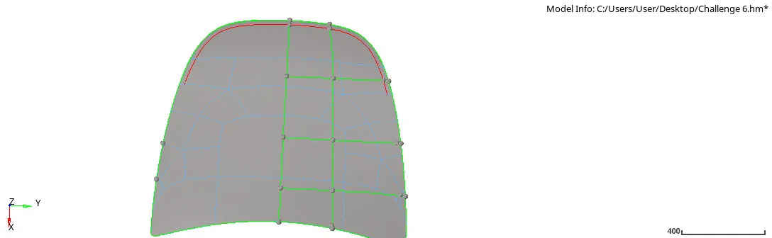
Fig 25: Rectangular partition
- Meshing has done by selecting surface to surface from top to the bottom, fixing the rotational quads, back to back trias, opposite trias, and trias on the edge.
- Those errors were fixed by the splitting them, re-mesh them until those trias are converted into quads, and simultaneously the quality criteria tools are also used to fix the errors to achieve the quality of the part.
- Working on the first half surface of the part, the element is reflected on the second surface. firstly by deleting the surface and then giving command [Tools + reflect + selecting the element] selecting the elements with attached and getting duplicate of the elements to remain primary elements on 1st half surface. Then giving Y-axis direction bis selecting the base node at bottom of the surface and reflecting the elements.
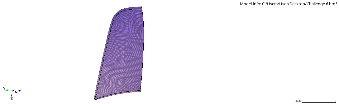
Fig 26: Deleted elements outer extract
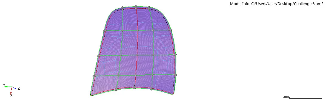
Fig 27: Reflecting elements and surface outer extract
- Whereas the same process is followed to achieve to get the surface of 2nd half for the elements.
- Completing the reflect section, it checked by the elements that have connectivity between 2 surfaces and it is fixed by the edges equivalence.
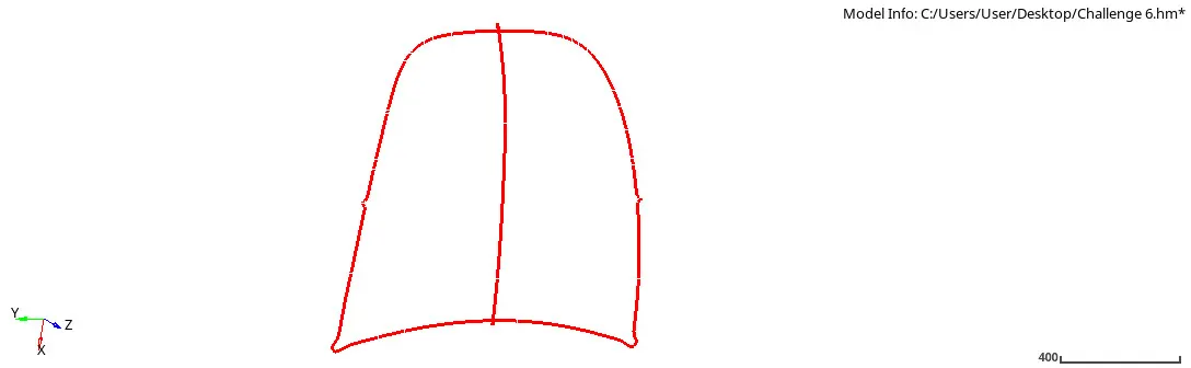
Fig 28: Edges equivalence
- And finally, it is checked for the quality criteria and errors which are found are fixed by the element optimize. But at the teeming part because it hemming part and difficult to capture mesh properly it showed the error and the element was below minimum size 2mm.
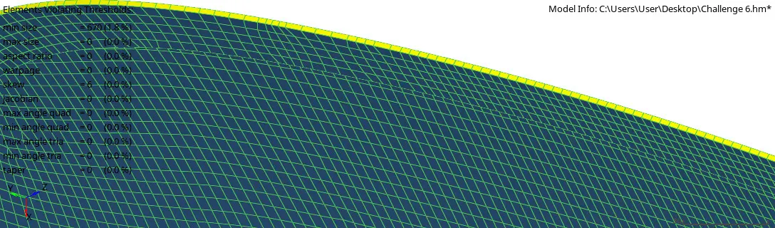
Fig 29: Min size error in hemming outer surf
- The thickness of 1.2mm and material steel is assigned to the outer extract body.
Inner extract body 1
- The inner part has several surfaces, they have symmetrical parts on both sides, so the second half surface is deleted and worked on the remaining first half surface except the top latch part because the geometry is different at both surface and it cannot be reflected.
- On remaining, surfaces worked on geometry cleanup and mesh [Criteria of meshing: Meshing Type: Mixed and Element size: 5mm].
- As the Hing part spline surfaces were missing, so created a line node to node and then created spline to have shared edges.
- As the inner surface has several parts and it's difficult to have fine mesh on the surface, to get it properly done it is divide into the smaller parts.
- The Surfaces are divided into smaller rectangular surfaces to have proper mesh wherever possible but while connecting with the different surfaces it getting free edges.
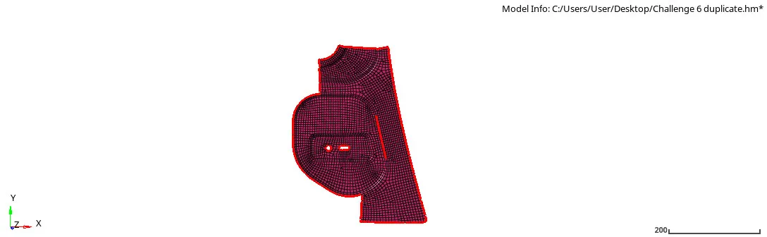
Fig 30: Edges on Inner surfaces
- The free edges are removed with equivalence and manually ith replacing the node.
- At the circle adding the washer split of 5mm to capture normal quad elements. while correcting errors at the curve surface, probably meshing at such surface getting warpage which fixed by splitting the surface and moving the trias at some distance.
- Opposite trias are not removed which are at different surfaces to avoid alignment of elements and also it is acceptable at big parts.
- While fixing errors on given quality criteria always maintain the elements align to the feature line.
- All errors are fixed and achieved the fine mesh with maintaining the trias management and proper quads. Those elements are reflected on the second half surface of the inner body component with reflecting the surfaces using the same command.
- After reflecting worked on the hatch part.
- Assigning the material and thickness of 1.2mm to inner body component.
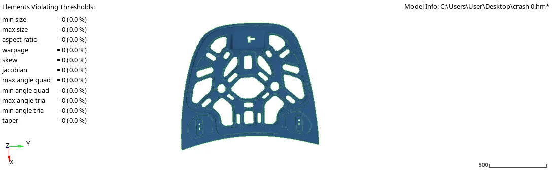
Fig 31 Quality output Inner Body
RESULT AND CONCLUSION:
The hood part has 5 different components those all components are meshed with [{Mesh type: Mixed and Quads} {Mesh elements size: 5mm}] with given quality condition as mentioned in the above. To get output following trias management rule is applied and maintaining the fine mesh at each, after working with all conditions the hood component is achieved with 0% error output except at outer body due to the hemming part which did not capture the mesh element properly due to the shared line and geometry error.
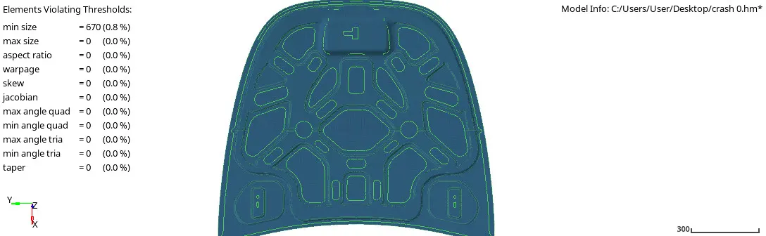
Fig 32 Hood quality output